Control decorative lighting on Arduino from your phone
Foreword
Last summer, I became interested in creating a system of decorative monochrome lighting with LEDs for an apartment under repair, and the question arose on the basis of which to assemble it.
I wanted to be able to:
- To control the backlight modes (fading speed, luminance intensity) remotely, from an Android phone on the bluetooth or a remote control of home appliances via IR
- The possibility of easy reprogramming modes of operation on the device itself
- Cost - the less the better
- Availability of components
The choice was simple - and I became the owner of a Chinese copy of the Arduino Uno3 called DK-Duino Uno, bought for 15 evergreens on ebee. Simultaneously with the controller, the LEDs themselves were purchased (blue, 3 bucks per hundred), the HC-05 bluetooth module for $ 12 and a 12V / 5A power supply unit for $ 7 - for a total of $ 37, or 1,100 rubles. On ebee there is an opportunity to buy sets of LED tape 5m + controller + IR remote for $ 17, but this option did not fit because of the need to direct the console to the receiver of the controller, which is planned to hide behind furniture / plinth.
The idea did not shine with originality, I just wanted to create something comfortable, durable and clear in the management of all residents of the house.
')
Idea
The LEDs located along the walls are located in the holes drilled in the laminate / parquet, a short distance from the wall (there were already a couple of posts about the similar arrangement of LEDs). When turned on - a smooth change in the brightness of individual LEDs with simultaneous displacement along the wall of the brightest - like landing lights on the runway.
What I wanted to translate into the backlight system
- Change of speed and brightness of a luminescence, up to full shutdown
- Bright mode
- Attenuation mode without running
Implementation - Arduino
To manage, I chose the phone on Android and the bluetooth, as the easiest way, not tied to the command system of a particular console, not subject to the problems of transmitting commands through obstacles like wall-furniture-cats.
The basis was taken from one of the many schemes of running fire with attenuation, found in the vastness of the infinite.
The maximum number of LEDs is 6, according to the number of PWM outputs of the selected Arduino.
What was needed to complete: the ability to connect the bluetooth module to receive control commands and send current status data to the phone for display.
I successfully coped with this, the result was a sketch for Arduino:
Sketch code
#include <SoftwareSerial.h> enum LedState { LED_ON, LED_OFF }; boolean isFadeMode = false; #define LED_CNT 6 int ledPins[LED_CNT] = {11, 10, 9, 6, 5, 3}; // pwm pins int ledBrightnessesWave[LED_CNT] = {0, 50, 100, 150, 205, 255}; // represents initial brightness for wave mode int ledStepsWave[LED_CNT] = {-5, 5, 5, 5, 5, 5}; // represents initial change for wave mode int ledBrightnesses[LED_CNT]; // represents brightness for pin int ledSteps[LED_CNT]; // represents change, each pin gets its own change so it wont interfere with any other pin int ledSpeed = 50; int maxLedBrightness = 255; int ledBrightnessesConst = 255; // represents brightness for pins in no wave or fade mode LedState led_state; #define rxPin 2 #define txPin 4 #define SPEED_PREFIX 'G' #define SPEED_PREFIX_MAX 'P' #define BRIGHTNESS_PREFIX 'Q' #define BRIGHTNESS_PREFIX_MAX 'Z' #define MIN_SPEED_DELAY 5 #define MAX_SPEED_DELAY 100 #define MIN_BRIGHTNESS 5 #define MAX_BRIGHTNESS 255 // set up a new serial port SoftwareSerial mySerial = SoftwareSerial(rxPin, txPin); void setup() { for (int i = 0; i < LED_CNT; i++) { pinMode(ledPins[i], OUTPUT); //set pwm pins to output //copy initial values ledBrightnesses[i] = ledBrightnessesWave[i]; ledSteps[i] = ledStepsWave[i]; } led_state = LED_ON; Serial.begin(9600); pinMode(rxPin, INPUT); pinMode(txPin, OUTPUT); mySerial.begin(115200); } int getBrightness(int b) { return b; } int valueToDelay(int value) { return MIN_SPEED_DELAY + (MAX_SPEED_DELAY - MIN_SPEED_DELAY) * value / (SPEED_PREFIX_MAX - SPEED_PREFIX); } int valueToBrightness(int value) { return MIN_BRIGHTNESS + (MAX_BRIGHTNESS - MIN_BRIGHTNESS) * value / (BRIGHTNESS_PREFIX_MAX - BRIGHTNESS_PREFIX); } void recalculateBrightness(int brValue) { ledBrightnessesConst = valueToBrightness(brValue); } void ledFade() { if (led_state == LED_OFF) { for (int i = 0; i < LED_CNT; i++) { analogWrite(ledPins[i], ledBrightnessesConst); // update all pins } return; } String s = "###"; for (int i = 0; i < LED_CNT; i++) { analogWrite(ledPins[i], getBrightness(ledBrightnesses[i])); int newBr = ledBrightnesses[i] + ledSteps[i]; if (newBr <= 0 || newBr >= maxLedBrightness) { ledSteps[i] =- ledSteps[i]; //change direction if exceeds max/min value } else { ledBrightnesses[i] = newBr; } s.concat(ledBrightnesses[i]); if (i < LED_CNT - 1) //skip separator for last entity s.concat("-"); } s.concat("***"); char charBuf[1000]; s.toCharArray(charBuf, 1000); mySerial.write(charBuf); mySerial.flush(); delay(ledSpeed); } void loop() { if (mySerial.available()) { char command = mySerial.read(); Serial.println("command is -> " + command); boolean handled = false; boolean changeFadeMode = false; switch (command) { case 'a': led_state = LED_OFF; handled = true; break; case 'b': led_state = LED_ON; ledSpeed = 50; handled = true; //do these lines to set wave mode changeFadeMode = true; isFadeMode = true; break; case 'c': led_state = LED_ON; ledSpeed = 30; handled = true; //do these lines to set wave mode changeFadeMode = true; isFadeMode = true; break; case 'd': led_state = LED_ON; ledSpeed = 10; handled = true; //do these lines to set wave mode changeFadeMode = true; isFadeMode = true; break; case 'e': led_state = LED_ON; changeFadeMode = true; handled = true; break; default: break; } if (changeFadeMode) { if (isFadeMode) { Serial.println("Set fade mode off"); for (int i = 0; i < LED_CNT; i++) { //copy initial values ledBrightnesses[i] = ledBrightnessesWave[i]; ledSteps[i] = ledStepsWave[i]; } } else { Serial.println("Set fade mode on"); for (int i = 0; i < LED_CNT; i++) { ledBrightnesses[i] = 0; ledSteps[i] = 5; } } isFadeMode = !isFadeMode; } else { //do nothing } if (!handled) { boolean isSpeedCommand = command >= SPEED_PREFIX && command <= SPEED_PREFIX_MAX; boolean isBrCommand = command >= BRIGHTNESS_PREFIX && command <= BRIGHTNESS_PREFIX_MAX; if (isSpeedCommand) { led_state = LED_ON; int speedValue = command - SPEED_PREFIX; //from 0 to 9 ledSpeed = valueToDelay(speedValue); } if (isBrCommand) { led_state = LED_OFF; int brValue = command - BRIGHTNESS_PREFIX; //from 0 to 9 recalculateBrightness(brValue); } } } ledFade(); } Depending on the command received, the controller either changes the speed or the brightness of the LEDs. You can also program any arbitrary actions on the received command - in the example I turn off the backlight and change the speed.
In each cycle, the controller sends a bluetooth string to the paired device on the form ### 0-50-100-150-200-250 ***, where the numbers are the brightness values of six LEDs, with a maximum of 255.
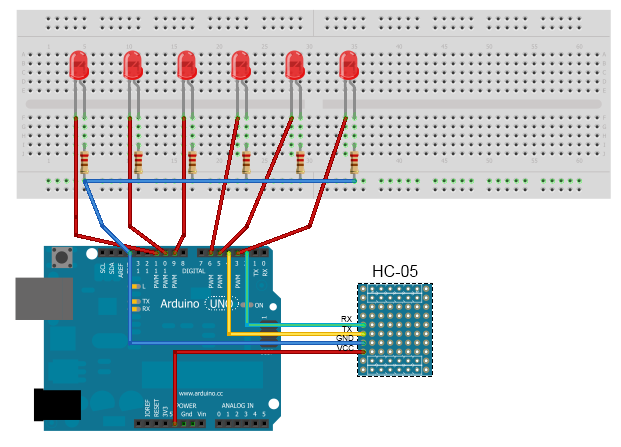
Scheme:
Problems
What faced: the inability to receive multi-character commands from the phone. For example, by sending the command s150 (according to the idea - to set the speed of 150 parrots with a maximum of 255), I received instead of the transferred string a complete nonsense like s ###, where instead of Sharp there were any ASCII characters. Perhaps this is due to the use of the SoftwareSerial class to connect the bluetooth. Smoking Google showed that I am not the only one lucky with this problem, but there is no solution other than changing the modes of the HC-05 module. There was no desire to bother with AT commands, so I decided to use only single-character commands from certain ranges, especially for the task that was quite enough. For example - for the speed of 10 values and commands from G to P, for brightness - range from Q to Z, respectively.
Implementation - Android
An application was written for the phone, with the ability to specify the transmitted commands without rewriting and compiling the code - for universality.
Screenshots of the application:
 |  |  |
There were no special problems - there is good documentation, and a very good one, as well as a huge number of tips on StackOverflow. But I had to deal with something — for example, the inability to connect to Arduino using the standard BluetoothDevice class method:
// Get a BluetoothSocket to connect with the given BluetoothDevice try { // MY_UUID is the app's UUID string, also used by the server code tmp = device.createRfcommSocketToServiceRecord(MY_UUID); } catch (IOException e) { } Instead, I had to climb into the reflex and pull the private method:
try { Class class1 = device.getClass(); Class aclass[] = new Class[1]; aclass[0] = Integer.TYPE; Method method = class1.getMethod("createRfcommSocket", aclass); Object aobj[] = new Object[1]; aobj[0] = Integer.valueOf(1); tmp = (BluetoothSocket)method.invoke(device, aobj); } What is the reason for this problem is unknown, but it occurs for many.
Another problem arose when parsing the string received from the microcontroller. Instead of lines like ### 0-50-100-150-200-250 *** ### 0-50-100-150-200-250 *** ... sometimes there were lines with an incorrect number of elements, incorrect separators or markers start / end sequence. I solved the problem by writing the received string analyzer and discarding the wrong sequences. After that, it was easy to implement a view with the display of the current state of the LEDs.
Results
A working application for the phone and a sketch for Arduino, the working scheme on the layout.
Video of the example of the scheme:
What's next:
- Actually the final soldering of the circuit and wiring of all the wires-LEDs around the room
- Connecting the volume-presence modules to enable / disable the system depending on the presence of a person in the room
- Connecting the clock module - why the daytime lights?
All sources are available here: code.google.com/p/arduinopad
Updates:
Arduino maximum at pwm output can produce 40 mA. Therefore, if you need more current - use for example the transistor BC557 - get up to 100 mA. If more is needed, then you can use any driver, for example, ULN2803APG - there will already be up to a half ampere per channel.
Source: https://habr.com/ru/post/165861/
All Articles