LogicDiscovery - simple logic analyzer
Quite often in home electronic crafts there is a need to look at one or another signal, and its digital representation is enough - what the MK sends on I2C, is the PWM configured correctly, etc. If you have a good oscilloscope at work, then buying it for your home is too expensive, especially when the need arises only occasionally.
Recently, inexpensive (within $ 50) logic analyzers have appeared, but one thought has always stopped me from buying them: the thing is extremely simple, why not make it your own from scrap materials?
In this article I will explain how to make a simple logic analyzer with minimal financial costs - all you need is a Stm32F4Discovery debugging board.
Logic analyzer (hereinafter LA) is a device intended for recording, viewing and analyzing signals in digital circuits. Like an oscilloscope, an aircraft is connected by one or several probes to the circuit being analyzed, but unlike an oscilloscope it records only two signal states “0” and “1”. An important function of the aircraft is the ability to automatically decipher the recorded signals, for example, to parse the data exchange on the I2C or SPI bus. Also, LAs differ in more, compared with oscilloscopes, the number of analyzed lines: from 8 in simple analyzers to hundreds in industrial designs.
The project described here, LogicDiscovery, is a SUMP- compatible logic analyzer, made in the format of a USB device to a PC. It has rather modest characteristics: 20MHz, 16 channels, 24kB of memory. However, this is sufficient for a very large range of tasks: analysis of UART, I2C, SPI lines (within a few megahertz), parallel buses, measurement of time characteristics of signals, etc.
So, all we need is this:
The client is written in Java, so the resulting solution does not depend on the OS. Theoretically, you can use any SUMP-compatible client, but below I will describe how to work with this program.
Stm32F4Discovery is powered by a mini-USB port, through which it is flashed. To use the functions of the aircraft, the board is connected to the PC via the micro USB port. To power the board from the same port, we connect PA9 and 5V pins with a jumper. PA9 is connected directly to the Vbus port of micro-USB, and 5V is the input of the stabilizer that forms power to the board. To test operation, connect the ports PA2 and PD0 . A test signal is generated on PA2, and PD0 is the first input of the aircraft.

')
The board is recognized by the PC as a COM port, for Linux the drivers are standard and should already be in the kernel, for Win the drivers are downloaded from the ST site. Once the board has been identified, you can start the client and get to work.
But first a spoon of tar.
The project uses the open protocol SUMP . This protocol was originally developed for FPGA-based aircrafts, and since, in terms of recording input signals and analyzing data flow, microcontrollers are still inferior to them, not all of the functions implemented in the client will be available to us:
These restrictions should be kept in mind when setting up the client. He knows nothing about these restrictions and will allow you to select any settings. The result obtained in this case will be incorrect.
We start the client through the run.bat or run.sh file, depending on the OS being used. You can read about the client's functions on his page, here I will describe the process of obtaining the first samples and those settings that fall under the restrictions.
In the “Capture” menu, selecting the “Begin capture” option , open the recording settings window. On the first page, in the field “Analyzer port”, we select the port on which our aircraft is sitting; nothing else needs to be changed. With the button “Show device metadata” you can check the connection:

On the second page we specify the capture parameters. The first two points do not touch,
“Sampling rate” is not higher than 20 MHz (if you specify more - the board still uses 20 MHz, but the client will think that the specified value is used, in general, the nonsense will work out).
“Channel groups” : 0 - use one group of channels, these are the PD0-PD7 lines, or 0 and 1 - we use two groups of channels - the PD0-PD15 lines.
“Recording size” : for one channel group - any value, for two groups - no more than 12kB (the client will warn you if an incorrect value is selected in this field).
Checkboxes on this page do not touch, they are not supported:

The "Triggers" page is the most interesting. The first checkbox is set to simply enable the triggers.
“Before / After ratio” allows you to specify, as a percentage, how much data is saved until the buffer is triggered. After clicking “Capture”, the LA immediately starts recording data, adding them to a cyclic buffer, and when the trigger is triggered, it reads the percentage of time specified in the After field and sends the data to the PC.
“Type” - only “Simple”, “Complex” - is not supported.
"Mode" - only "Parallel".
“Mask” are those lines on which the trigger will wait for the signal to drop, set the flag in the zero position to trigger on the PD0 line
“Value” - the front of the signal, which will trigger the trigger. The checkbox is set to the front edge. Checkbox cleared - back:

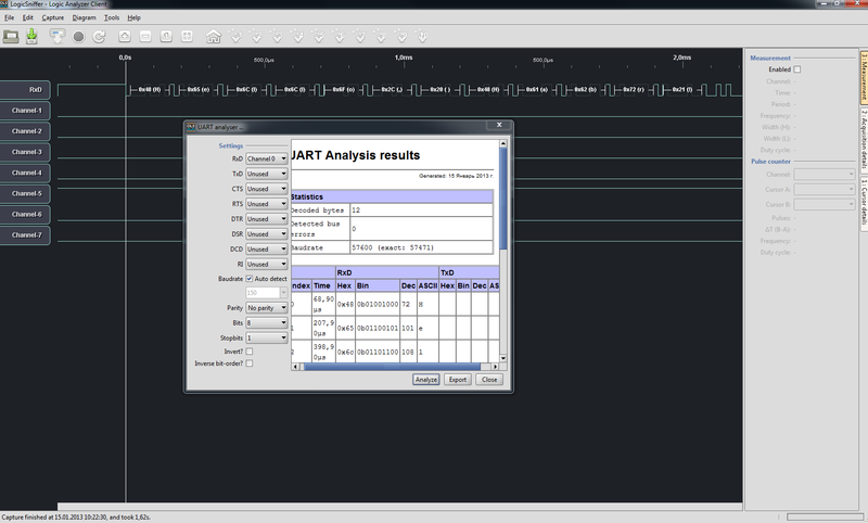
To test the operation, connect the ports PD0 and PA2 (this port displays the UART test signal) with a jumper.
That's all, click "Capture" and look at the received signal (Ctrl + F - overview scale):
If nothing happens, it means that you have triggered the trigger on the wrong lines, or there is no signal at all - check the settings and wiring of the board. The trigger can be started manually by pressing the User button (blue button).
Remember: you connect directly to the ports of the microcontroller! There is no protection other than the built-in diodes on the MK board. Therefore, first make sure that the signal under study has a maximum voltage of 3.3V, at most 5V, but then it is desirable to add a protective resistor between the signal source and the aircraft.
When connecting to the analyzed circuit, do not forget to first connect the earth, and only then the signal lines. Especially when the analyzed circuit is powered from its power source, and not from the same PC to which the aircraft is connected.
Project page on Google.Code
STM32F4Discovery card description
Open Logic Sniffer - a project that served as a source of inspiration for this work.
PS: LogicDiscovery is successfully used both at home and at work, mainly for analyzing serial interfaces (SPI, UART). If there are any suggestions for expanding the functionality, I will be glad to hear. Consider only that a lot rests on the limitations of the client, for example, the sample size on F4 can be made many times larger, but the client simply does not know other sizes.
Recently, inexpensive (within $ 50) logic analyzers have appeared, but one thought has always stopped me from buying them: the thing is extremely simple, why not make it your own from scrap materials?
In this article I will explain how to make a simple logic analyzer with minimal financial costs - all you need is a Stm32F4Discovery debugging board.
Logic analyzer (hereinafter LA) is a device intended for recording, viewing and analyzing signals in digital circuits. Like an oscilloscope, an aircraft is connected by one or several probes to the circuit being analyzed, but unlike an oscilloscope it records only two signal states “0” and “1”. An important function of the aircraft is the ability to automatically decipher the recorded signals, for example, to parse the data exchange on the I2C or SPI bus. Also, LAs differ in more, compared with oscilloscopes, the number of analyzed lines: from 8 in simple analyzers to hundreds in industrial designs.
The project described here, LogicDiscovery, is a SUMP- compatible logic analyzer, made in the format of a USB device to a PC. It has rather modest characteristics: 20MHz, 16 channels, 24kB of memory. However, this is sufficient for a very large range of tasks: analysis of UART, I2C, SPI lines (within a few megahertz), parallel buses, measurement of time characteristics of signals, etc.
Let's get started
So, all we need is this:
- Stm32F4Discovery debug board. From 500 rubles in Moscow retail, and maybe it already lies in your bins? Any other board on STM32F4 or STM32F2 will do, but then you have to tweak the sources.
- Several wires to connect to the analyzed circuit.
- Ready-to-use firmware rests on Google.Code . There are also sources.
- In addition, you need a client for a PC, I recommend OLS .
The client is written in Java, so the resulting solution does not depend on the OS. Theoretically, you can use any SUMP-compatible client, but below I will describe how to work with this program.
Stm32F4Discovery is powered by a mini-USB port, through which it is flashed. To use the functions of the aircraft, the board is connected to the PC via the micro USB port. To power the board from the same port, we connect PA9 and 5V pins with a jumper. PA9 is connected directly to the Vbus port of micro-USB, and 5V is the input of the stabilizer that forms power to the board. To test operation, connect the ports PA2 and PD0 . A test signal is generated on PA2, and PD0 is the first input of the aircraft.
')
The board is recognized by the PC as a COM port, for Linux the drivers are standard and should already be in the kernel, for Win the drivers are downloaded from the ST site. Once the board has been identified, you can start the client and get to work.
But first a spoon of tar.
Restrictions
The project uses the open protocol SUMP . This protocol was originally developed for FPGA-based aircrafts, and since, in terms of recording input signals and analyzing data flow, microcontrollers are still inferior to them, not all of the functions implemented in the client will be available to us:
- The maximum recording frequency is 20 MHz, in the original up to 200 MHz
- RLE compression and noise filtering are not supported.
- It is impossible to choose arbitrary groups of channels, only the first (8 channels), or the first + second (16 channels).
- Triggers work not by value, but by front (however, in my opinion, this is already a merit).
- No support for extended (Complex) triggers.
These restrictions should be kept in mind when setting up the client. He knows nothing about these restrictions and will allow you to select any settings. The result obtained in this case will be incorrect.
We use
We start the client through the run.bat or run.sh file, depending on the OS being used. You can read about the client's functions on his page, here I will describe the process of obtaining the first samples and those settings that fall under the restrictions.
In the “Capture” menu, selecting the “Begin capture” option , open the recording settings window. On the first page, in the field “Analyzer port”, we select the port on which our aircraft is sitting; nothing else needs to be changed. With the button “Show device metadata” you can check the connection:
On the second page we specify the capture parameters. The first two points do not touch,
“Sampling rate” is not higher than 20 MHz (if you specify more - the board still uses 20 MHz, but the client will think that the specified value is used, in general, the nonsense will work out).
“Channel groups” : 0 - use one group of channels, these are the PD0-PD7 lines, or 0 and 1 - we use two groups of channels - the PD0-PD15 lines.
“Recording size” : for one channel group - any value, for two groups - no more than 12kB (the client will warn you if an incorrect value is selected in this field).
Checkboxes on this page do not touch, they are not supported:
The "Triggers" page is the most interesting. The first checkbox is set to simply enable the triggers.
“Before / After ratio” allows you to specify, as a percentage, how much data is saved until the buffer is triggered. After clicking “Capture”, the LA immediately starts recording data, adding them to a cyclic buffer, and when the trigger is triggered, it reads the percentage of time specified in the After field and sends the data to the PC.
“Type” - only “Simple”, “Complex” - is not supported.
"Mode" - only "Parallel".
“Mask” are those lines on which the trigger will wait for the signal to drop, set the flag in the zero position to trigger on the PD0 line
“Value” - the front of the signal, which will trigger the trigger. The checkbox is set to the front edge. Checkbox cleared - back:
To test the operation, connect the ports PD0 and PA2 (this port displays the UART test signal) with a jumper.
That's all, click "Capture" and look at the received signal (Ctrl + F - overview scale):
If nothing happens, it means that you have triggered the trigger on the wrong lines, or there is no signal at all - check the settings and wiring of the board. The trigger can be started manually by pressing the User button (blue button).
Safety
Remember: you connect directly to the ports of the microcontroller! There is no protection other than the built-in diodes on the MK board. Therefore, first make sure that the signal under study has a maximum voltage of 3.3V, at most 5V, but then it is desirable to add a protective resistor between the signal source and the aircraft.
When connecting to the analyzed circuit, do not forget to first connect the earth, and only then the signal lines. Especially when the analyzed circuit is powered from its power source, and not from the same PC to which the aircraft is connected.
Utility
Project page on Google.Code
STM32F4Discovery card description
Open Logic Sniffer - a project that served as a source of inspiration for this work.
PS: LogicDiscovery is successfully used both at home and at work, mainly for analyzing serial interfaces (SPI, UART). If there are any suggestions for expanding the functionality, I will be glad to hear. Consider only that a lot rests on the limitations of the client, for example, the sample size on F4 can be made many times larger, but the client simply does not know other sizes.
Source: https://habr.com/ru/post/165853/
All Articles