What's inside the cable station headend
On Habré there is a post about the head station IPTV. It was told about the methods of receiving and further signal transmission from satellites over IP networks. I will write about what is included in the head station of cable television and how it all works. Caution, a lot of pictures and text.
As I wrote at the beginning, in contrast to IPTV, the head station KTV should be in every place where an abundance of subscribers is planned. The reason is simple - the subscriber already receives a signal in the KTV in a completely different environment - a coaxial cable, it will not be able to transmit it via the IP network. At the same time, broadcasting received from satellites can be easily transmitted from the Main Trunk Station (IGU) to the Regional (CWG) in the form of a Multicast via the IP network. Below is an example from the concept.

Of course, large operators may have several IGUs in order to reserve and accept channels from different geographically distant satellites.
Still somewhere it is necessary to take the local terrestrial TV channels. You need to show local weather, advertising, news. There are two options for this - either pick them up with a regular on-air antenna from the air, digitize, convert and transfer to the subscriber, or pick them up directly from the content owners (RTPC). The second option is usually more expensive - you need to dock with third-party organization, place your equipment . Therefore, mostly local channels are taken from the air.
')
People often get confused about what they watch on their TV. In general, 3 types of broadcasting are now distributed.
Each type has its own advantage.
Analog TV is good because it will work in any old TV without using any converters. For each channel, the 8MHz band is allocated here; if you look at the spectrum measurements with the instrument, you will clearly see the carrier of sound and images.
Digital television (DVB) uses the same frequencies as analog. The key difference is that many channels can be stuck in the 8MHz band. You will not see a separate carrier in this band; the signal will be evenly distributed over it. In addition, due to the fact that the signal is now digital, it is possible to encrypt it. With this approach, it has become possible to create channel packages for subscribers. There is nothing tricky about them - all channels (in fact, not all) come to you in encrypted form, and the card inserted in the console contains the key to decrypting them.
The DVB format itself defines the logic for compressing several channels into one frequency band. There are different types of DVB, for example DVB-C (cable), DVB-T (terrestrial), DVB-S (satellite). The disadvantages of DVB can be attributed to the fact that the subscriber is now required to put additional equipment and mess around with the card.
IPTV is great for subscribers, but the provider is harder to work with. It gives additional load on the existing subscriber IP-network. Multicast rules here. As in DVB, you can receive absolutely all channels, but some will be encrypted. Unlike DVB, IP-network implies not only the channel from the provider to the subscriber, but also reverse. This allows you to use to decrypt already, for example a pair of login-password. In general, good about IPTV is written here .
About the "Internet TV" is not particularly talk about, it seems like it is clear to most. Normal video content is transmitted in most cases via HTTP. The provider is not responsible for its quality.
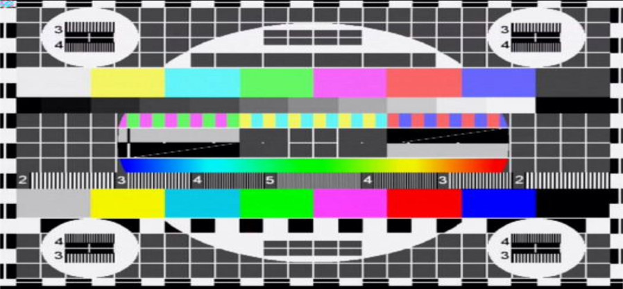
The image below shows an example of the joint broadcasting of analog and digital (DVB-C) television in the same frequency grid.

In my example, the analog channel broadcasts one channel (in my opinion, "Carousel"), and in the figure there are 8 different channels. It is clearly visible that in the digital form the information is evenly distributed across the width, and in the analog one two carrier images and sounds are clearly distinguished.
The key distinctive feature of cable television from IPTV / “via the Internet” is that the information is transmitted only to the subscriber (are we not going to consider DOCSIS?), From him there will be no answers to your equipment about poor quality signals, errors or something else that In any case, first of all you will have to go to him with your time-tested TV and measuring instruments.
Also, unlike IP networks, if it’s gone from you, it’s not a fact that the same will come to the subscriber. There are no checksums of checksums (in digital, in fact, but if they are incorrect, the picture will just disappear), confirmation of the authenticity of the information ...
I anticipate holivar IPTV vs KTV.
Let's just count: one SD-quality channel (480p) can be transmitted with acceptable quality with a bitrate of 3-4 MBps. HD quality is 8-10 MBps. Total, having in the set of channels 180SD + 20HD, the operator needs to spend only about 1GBps (or even more) on uplinks of their equipment. This is not yet taking into account the video with recordings from different places, several audio tracks. At the moment, the usual mass wired Internet operators have common uplinks between 1GBps home nodes. Television shove in the current infrastructure is difficult.
On the other hand, after building for the Internet service, “dark” (unused) fibers in fiber optic cables remained, because they are usually put in with a margin. They can be used for our purposes. In addition, there are a huge number of places where technologies such as G (E) PON, with which cable television is easily integrated, are gaining momentum.
In addition, the cable television system itself is less whimsical and simpler than IP networks. Here you do not need to take into account any QoS, port matching, channel dubbing, incorrect routing. And this means that less attention is required to the house nodes, you can try to “put and forget” (of course, when connecting a new client, you may have to turn up the frequency response and power on the house receiver).
In addition, an ordinary user is still not very accustomed to IPTV, and home TVs that support this technology out of the box without prefixes, too, have not yet appeared in huge numbers.
My opinion is that today the mass user is not ready for IPTV. As a mass operator.
The concept of the head station is very vague. For example, a video capture device with an AUX OUT port can be called a “head station”. It will broadcast the whole channel with something incomprehensible. However, we have a very specific goal - to organize the broadcasting of many channels with real content for a heap of subscribers. To this end, our station includes the following:
Now I will give an approximate scheme of a specific CSG:
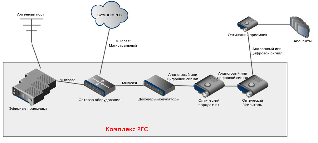
It is clear that the composition may vary depending on the situation. For example, if you have a convenient location and it is easy to dock with local channels via an IP network, you may not need an antenna post in principle.
If the image quality of local channels is unsatisfactory due to poor reception at the antenna post, it can be transferred to another place, it still leaves a clean multicast that can be driven through the IP network. In several cities, we succeeded.
As I already wrote in the theoretical part, the signal to the subscriber can go either analog or digital. Given that the digital signal works in the same frequency grid, this is no problem.
For transmission between optical amplifiers / receivers, a laser signal is used through an optical fiber at a wavelength of 1550nm. For connections, the “oblique” APC polish is used. Something like DWDM.
The complex itself is not very big - a pair of racks:
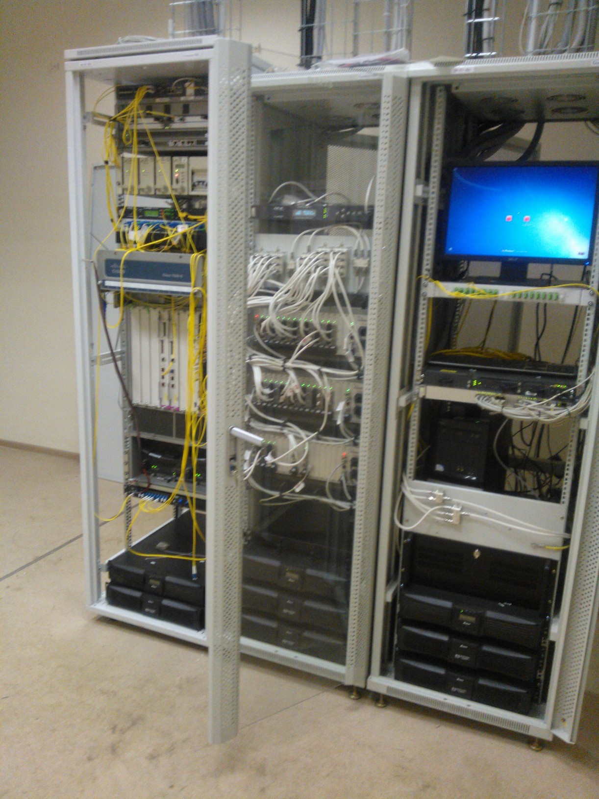
In the figure, the leftmost rack does not count, there the equipment is intended for another. In addition, it is useful to add monitoring equipment to the rack.
As I wrote above, it is necessary to organize the reception of local federal channels (for example, “Russia 1”, “ORT”). In our case, they are taken as an analog signal and then converted to multicast. We use Anevia Flamingo 660 , which are analog encoders in multicast . By and large, this is a system unit with several TV tuners installed in it. Below is the image of the encoders back and front. Photos turned out not very good because of not the best lighting.
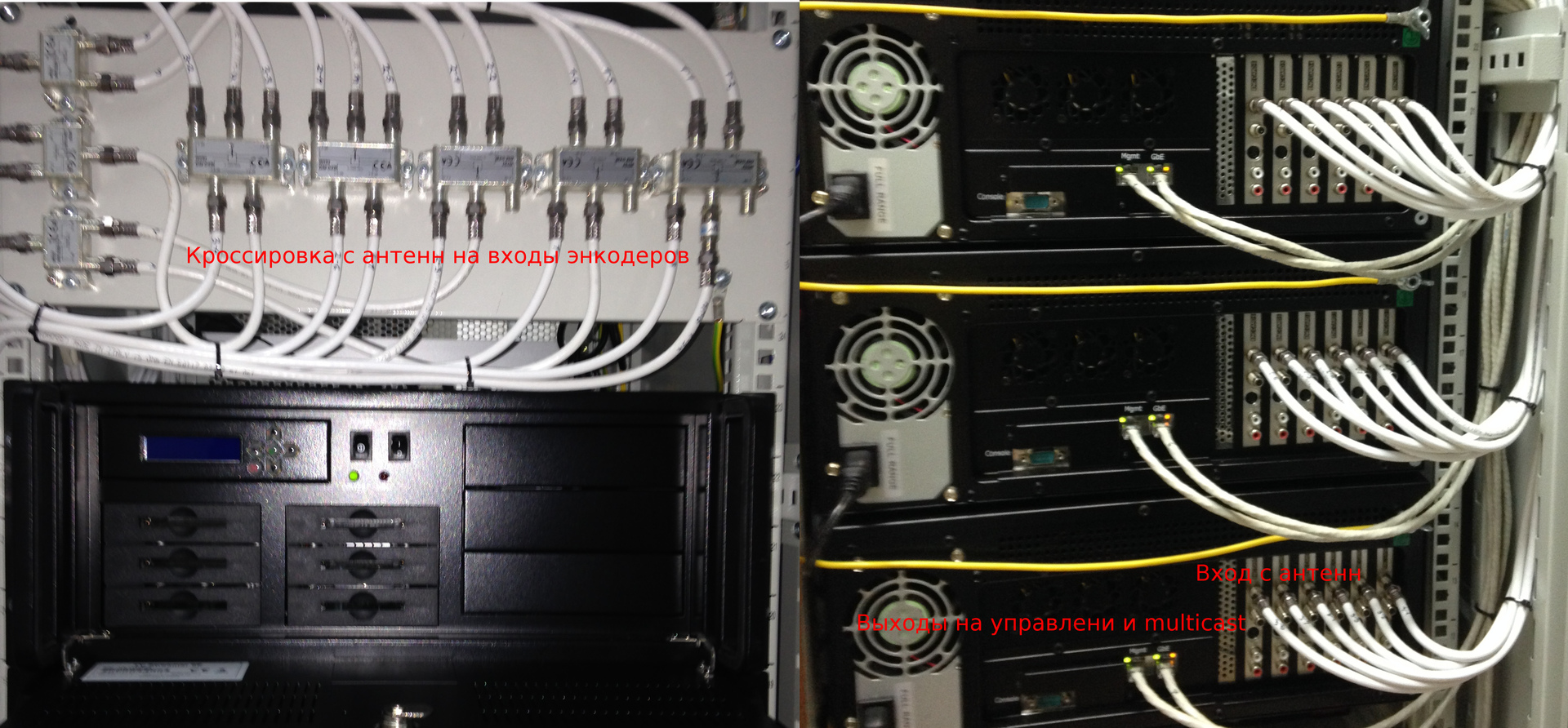
On the left there is also a bar for cross-connects of the outputs to the antennas with the inputs to the encoders. A kind of patch panel.
The signal of the broadcast channels should appear somewhere on the encoders described above. For this, an antenna post is placed nearby (on the roof) from the analog encoder. Since the broadcasting in our country is in the meter and decimeter bands, put two antennas. They are connected to encoders. Bottom photo from the roof (maybe someone will know your city?)

So, we figured out where to get the content. Part of the pick up local channels, part of the trunk head. On something you need to take Multicast traffic, route it, filter out the excess. As I wrote before, this is a regular switch (preferably L3).
All the adopted trunk (from the IGU) and local (from the antenna post) multicast are reduced here. In our case, this is the Catalyst 3750 with an additional power supply. Here multicast groups are mixed, part is given for monitoring, some local content can be transferred to other nearby cities. For Multicast routing raised PIM SM. On the switch, we still have control over all the glands from the CWG complex (there are many addresses — each board has its own address and you can enter it).

If your antenna post is removed from the modulators, then a switch will also be required on it.
We have the right content, it's time to transfer it to the cable television network. For this you need to turn it into a look that is understandable for TVs or set-top boxes. For this, the so-called signal delivery systems are used.
This is the most important piece of hardware. It just transforms everything into the kind that custom TVs or set-top boxes can swallow. Specifically, we have three AppearTV DC 1000 chassis with boards.
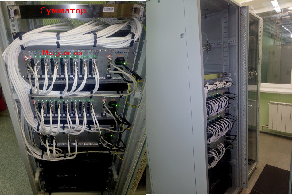
In the above case, the top two are encoded into an analog signal, and the bottom into a digital one. An analog signal is issued as follows - on each board 2 “nipples”, from each of which two channels can be given. Total 4 channels from the board. With the digital principle is the same, only in each "channel" (frequency range) is now a lot of channels. From one lower chassis with 2 boards, it takes as many real channels as from the top two fully packed chassis! A bunch of wires from each port goes to the adder and goes to the optical transmitter. Unfortunately, specifically with this CSG I do not have their photos, they will be from the station from another city.
Our modular hardware is a chassis (basket) in which boards are mounted for various needs. For example, for digital broadcasting, you can build encryption cards to sell television packages to subscribers.
A lot of coaxial wires go from the decoders to the common adder, and it will be the output of what will be further transmitted over the network. There is a trendy adder here, but in general terms it may just be a bar with several electrical dividers / couplers.
Great, we have all the signal we need! Now we need to deliver it directly to subscribers. In general, these are elements of the cable network and here you need to think what you need. But in general, as part of the CSG, an optical transmitter and an amplifier are used for this.
A coaxial cable enters the optical transmitter and the optical fiber goes out. A signal is transmitted over it at a wavelength of 1550 nm. The signal is mixed - the information is in both analog and digital form.

The image above is an optical transmitter, bottom - an optical amplifier. Please note - polishing on APC patch cords.
Well, then everything. Here, cable television network elements are already beginning - dividers, house optical receivers, electrical amplifiers and subscribers with their inactive TVs, hung consoles, and wire leads ...
We launched the head station and our subscribers can (if the equipment on the ground did everything correctly) to watch telvizor! Now the most interesting begins - our station should be serviced. For this it is useful to put auxiliary equipment.
Specifically, we have a regular computer with a TV tuner for remote viewing the availability of channels from the output of the CWG, VLC for viewing the Multicast stream at the entrance to the CWG. So far we haven't come up with anything smarter than just connecting via RDP and watching what is shown through the TV tuner. Of course, it is not very convenient, but typical problems (lack of image, lack of sound, incorrect color rendition of PAL / SECAM, etc.) can be solved.
A measuring device (planar) is also connected to it to estimate the signal power and signal-to-noise ratio. Well, at the same time, there is a constant broadcasting of the picture “the channel is temporarily unavailable”, which automatically turns on in case of failure of any channel.

I showed a basic idea of what the head station of cable television (CSG KTV) consists of and how it works. It is important to remember the general principle of passing content from the antenna to the subscriber:
Leave some useful links:
1. Table of frequencies of television channels in our country (OIRT)
2. Frequencies of terrestrial channels in cities of Russia
3. A good site with a detailed description of the principles of work
4. Frequencies of terrestrial and satellite channels
PS Thanks to the ProgerXP user for the service gliffy.com , in which the charts for this article were made.
General scheme
As I wrote at the beginning, in contrast to IPTV, the head station KTV should be in every place where an abundance of subscribers is planned. The reason is simple - the subscriber already receives a signal in the KTV in a completely different environment - a coaxial cable, it will not be able to transmit it via the IP network. At the same time, broadcasting received from satellites can be easily transmitted from the Main Trunk Station (IGU) to the Regional (CWG) in the form of a Multicast via the IP network. Below is an example from the concept.
Of course, large operators may have several IGUs in order to reserve and accept channels from different geographically distant satellites.
Still somewhere it is necessary to take the local terrestrial TV channels. You need to show local weather, advertising, news. There are two options for this - either pick them up with a regular on-air antenna from the air, digitize, convert and transfer to the subscriber, or pick them up directly from the content owners (RTPC). The second option is usually more expensive - you need to dock with third-party organization, place your equipment . Therefore, mostly local channels are taken from the air.
')
Some theory
People often get confused about what they watch on their TV. In general, 3 types of broadcasting are now distributed.
- Analog - you catch it with an ordinary antenna in the attic or balcony, although the operator can also sell it via cable
- Digital - DVB, now digital signal
- IPTV is a classic multicast that comes to your home via the Internet
- “Television via the Internet” - this usually means youtube, Smartv, in general, what you watch through normal requests
Each type has its own advantage.
Analog TV is good because it will work in any old TV without using any converters. For each channel, the 8MHz band is allocated here; if you look at the spectrum measurements with the instrument, you will clearly see the carrier of sound and images.
Digital television (DVB) uses the same frequencies as analog. The key difference is that many channels can be stuck in the 8MHz band. You will not see a separate carrier in this band; the signal will be evenly distributed over it. In addition, due to the fact that the signal is now digital, it is possible to encrypt it. With this approach, it has become possible to create channel packages for subscribers. There is nothing tricky about them - all channels (in fact, not all) come to you in encrypted form, and the card inserted in the console contains the key to decrypting them.
The DVB format itself defines the logic for compressing several channels into one frequency band. There are different types of DVB, for example DVB-C (cable), DVB-T (terrestrial), DVB-S (satellite). The disadvantages of DVB can be attributed to the fact that the subscriber is now required to put additional equipment and mess around with the card.
IPTV is great for subscribers, but the provider is harder to work with. It gives additional load on the existing subscriber IP-network. Multicast rules here. As in DVB, you can receive absolutely all channels, but some will be encrypted. Unlike DVB, IP-network implies not only the channel from the provider to the subscriber, but also reverse. This allows you to use to decrypt already, for example a pair of login-password. In general, good about IPTV is written here .
About the "Internet TV" is not particularly talk about, it seems like it is clear to most. Normal video content is transmitted in most cases via HTTP. The provider is not responsible for its quality.
The image below shows an example of the joint broadcasting of analog and digital (DVB-C) television in the same frequency grid.
In my example, the analog channel broadcasts one channel (in my opinion, "Carousel"), and in the figure there are 8 different channels. It is clearly visible that in the digital form the information is evenly distributed across the width, and in the analog one two carrier images and sounds are clearly distinguished.
The key distinctive feature of cable television from IPTV / “via the Internet” is that the information is transmitted only to the subscriber (are we not going to consider DOCSIS?), From him there will be no answers to your equipment about poor quality signals, errors or something else that In any case, first of all you will have to go to him with your time-tested TV and measuring instruments.
Also, unlike IP networks, if it’s gone from you, it’s not a fact that the same will come to the subscriber. There are no checksums of checksums (in digital, in fact, but if they are incorrect, the picture will just disappear), confirmation of the authenticity of the information ...
I anticipate holivar IPTV vs KTV.
Let's just count: one SD-quality channel (480p) can be transmitted with acceptable quality with a bitrate of 3-4 MBps. HD quality is 8-10 MBps. Total, having in the set of channels 180SD + 20HD, the operator needs to spend only about 1GBps (or even more) on uplinks of their equipment. This is not yet taking into account the video with recordings from different places, several audio tracks. At the moment, the usual mass wired Internet operators have common uplinks between 1GBps home nodes. Television shove in the current infrastructure is difficult.
On the other hand, after building for the Internet service, “dark” (unused) fibers in fiber optic cables remained, because they are usually put in with a margin. They can be used for our purposes. In addition, there are a huge number of places where technologies such as G (E) PON, with which cable television is easily integrated, are gaining momentum.
In addition, the cable television system itself is less whimsical and simpler than IP networks. Here you do not need to take into account any QoS, port matching, channel dubbing, incorrect routing. And this means that less attention is required to the house nodes, you can try to “put and forget” (of course, when connecting a new client, you may have to turn up the frequency response and power on the house receiver).
In addition, an ordinary user is still not very accustomed to IPTV, and home TVs that support this technology out of the box without prefixes, too, have not yet appeared in huge numbers.
My opinion is that today the mass user is not ready for IPTV. As a mass operator.
What's inside
The concept of the head station is very vague. For example, a video capture device with an AUX OUT port can be called a “head station”. It will broadcast the whole channel with something incomprehensible. However, we have a very specific goal - to organize the broadcasting of many channels with real content for a heap of subscribers. To this end, our station includes the following:
- Equipment for receiving local channels - assume that a bunch of TV tuners, they just take a terrestrial (or some other) signal and convert it to IP-multicast.
- Antenna post - several conventional antennas for receiving terrestrial television
- Decoders / Modulators - convert an IP multicast into a signal that custom TVs (digital or analog) can already receive
- Network equipment — typically a L3 switch (yes, L2 is also possible) to combine the multicast mix of local and trunk
- Channeling equipment - optical transmitter and amplifier
Now I will give an approximate scheme of a specific CSG:
It is clear that the composition may vary depending on the situation. For example, if you have a convenient location and it is easy to dock with local channels via an IP network, you may not need an antenna post in principle.
If the image quality of local channels is unsatisfactory due to poor reception at the antenna post, it can be transferred to another place, it still leaves a clean multicast that can be driven through the IP network. In several cities, we succeeded.
As I already wrote in the theoretical part, the signal to the subscriber can go either analog or digital. Given that the digital signal works in the same frequency grid, this is no problem.
For transmission between optical amplifiers / receivers, a laser signal is used through an optical fiber at a wavelength of 1550nm. For connections, the “oblique” APC polish is used. Something like DWDM.
The complex itself is not very big - a pair of racks:
In the figure, the leftmost rack does not count, there the equipment is intended for another. In addition, it is useful to add monitoring equipment to the rack.
Reception of local broadcasting
As I wrote above, it is necessary to organize the reception of local federal channels (for example, “Russia 1”, “ORT”). In our case, they are taken as an analog signal and then converted to multicast. We use Anevia Flamingo 660 , which are analog encoders in multicast . By and large, this is a system unit with several TV tuners installed in it. Below is the image of the encoders back and front. Photos turned out not very good because of not the best lighting.
On the left there is also a bar for cross-connects of the outputs to the antennas with the inputs to the encoders. A kind of patch panel.
Antenna post
The signal of the broadcast channels should appear somewhere on the encoders described above. For this, an antenna post is placed nearby (on the roof) from the analog encoder. Since the broadcasting in our country is in the meter and decimeter bands, put two antennas. They are connected to encoders. Bottom photo from the roof (maybe someone will know your city?)
network hardware
So, we figured out where to get the content. Part of the pick up local channels, part of the trunk head. On something you need to take Multicast traffic, route it, filter out the excess. As I wrote before, this is a regular switch (preferably L3).
All the adopted trunk (from the IGU) and local (from the antenna post) multicast are reduced here. In our case, this is the Catalyst 3750 with an additional power supply. Here multicast groups are mixed, part is given for monitoring, some local content can be transferred to other nearby cities. For Multicast routing raised PIM SM. On the switch, we still have control over all the glands from the CWG complex (there are many addresses — each board has its own address and you can enter it).
If your antenna post is removed from the modulators, then a switch will also be required on it.
Decoders / Modulators
We have the right content, it's time to transfer it to the cable television network. For this you need to turn it into a look that is understandable for TVs or set-top boxes. For this, the so-called signal delivery systems are used.
This is the most important piece of hardware. It just transforms everything into the kind that custom TVs or set-top boxes can swallow. Specifically, we have three AppearTV DC 1000 chassis with boards.
In the above case, the top two are encoded into an analog signal, and the bottom into a digital one. An analog signal is issued as follows - on each board 2 “nipples”, from each of which two channels can be given. Total 4 channels from the board. With the digital principle is the same, only in each "channel" (frequency range) is now a lot of channels. From one lower chassis with 2 boards, it takes as many real channels as from the top two fully packed chassis! A bunch of wires from each port goes to the adder and goes to the optical transmitter. Unfortunately, specifically with this CSG I do not have their photos, they will be from the station from another city.
Our modular hardware is a chassis (basket) in which boards are mounted for various needs. For example, for digital broadcasting, you can build encryption cards to sell television packages to subscribers.
A lot of coaxial wires go from the decoders to the common adder, and it will be the output of what will be further transmitted over the network. There is a trendy adder here, but in general terms it may just be a bar with several electrical dividers / couplers.
Channel-forming equipment
Great, we have all the signal we need! Now we need to deliver it directly to subscribers. In general, these are elements of the cable network and here you need to think what you need. But in general, as part of the CSG, an optical transmitter and an amplifier are used for this.
A coaxial cable enters the optical transmitter and the optical fiber goes out. A signal is transmitted over it at a wavelength of 1550 nm. The signal is mixed - the information is in both analog and digital form.
The image above is an optical transmitter, bottom - an optical amplifier. Please note - polishing on APC patch cords.
Well, then everything. Here, cable television network elements are already beginning - dividers, house optical receivers, electrical amplifiers and subscribers with their inactive TVs, hung consoles, and wire leads ...
Auxiliary equipment
We launched the head station and our subscribers can (if the equipment on the ground did everything correctly) to watch telvizor! Now the most interesting begins - our station should be serviced. For this it is useful to put auxiliary equipment.
Specifically, we have a regular computer with a TV tuner for remote viewing the availability of channels from the output of the CWG, VLC for viewing the Multicast stream at the entrance to the CWG. So far we haven't come up with anything smarter than just connecting via RDP and watching what is shown through the TV tuner. Of course, it is not very convenient, but typical problems (lack of image, lack of sound, incorrect color rendition of PAL / SECAM, etc.) can be solved.
A measuring device (planar) is also connected to it to estimate the signal power and signal-to-noise ratio. Well, at the same time, there is a constant broadcasting of the picture “the channel is temporarily unavailable”, which automatically turns on in case of failure of any channel.
Finally
I showed a basic idea of what the head station of cable television (CSG KTV) consists of and how it works. It is important to remember the general principle of passing content from the antenna to the subscriber:
- antenna
- Encoders (TV Tuners)
- switches
- modulators
- transmitters
Leave some useful links:
1. Table of frequencies of television channels in our country (OIRT)
2. Frequencies of terrestrial channels in cities of Russia
3. A good site with a detailed description of the principles of work
4. Frequencies of terrestrial and satellite channels
PS Thanks to the ProgerXP user for the service gliffy.com , in which the charts for this article were made.
Source: https://habr.com/ru/post/165643/
All Articles