Configuring Private VLANs on Cisco
In this article we will consider such an interesting, in my opinion, technology, as Private VLANs in theory and practice.
First, remember what VLANs are. VLAN is a separate subnet, a separate Broadcast domain, used for logical network segmentation, restriction of the broadcasting domain, security, etc.
Typically, a network is divided into VLANs, then using a router-on-the-stick or multi-level switch (any device of level 3), routing is enabled (all traffic is allowed), and then, using access control lists, it is prescribed to whom, with whom and the protocol is allowed to communicate (or traffic control is applied based on the requirements of your organization’s security policy, as it would have been written in a Cisco tutorial).
')
But what to do when, for example, the network is already divided, segmented, but it became necessary to isolate servers or groups of hosts from each other?
Cisco, like other vendors, has additional tools to help limit the forwarding of traffic between hosts that are within the same subnet or control traffic within a VLAN. For this, private VLANs (private VLANs), VLAN access list and protected ports are most often used.
It should be noted that Private VLANs on Cisco are supported on Nexus models, as well as Catalyst starting at 3560 and up .
On junior models switches there is such a thing as private vlan edge . It is configured very simply - from the configuration mode of the interface we write the command (config-if) #switchport protected, as a result, the hosts connected to these ports will be isolated from each other at level 2 (that is, physically they will be connected to one switch, be on the same subnet, but will not “see” each other, while all other hosts will “see”. One of the drawbacks of this mechanism is that it has a local value for the switch and does not scale (if we connect switch A and switch B with a trunk, for example, then the protected port of the switch A can “see” the protected port of the switch B).
Let us dwell in more detail on private VLANs. The main purpose of the article is to teach how to configure private VLANs, understand the terminology, as well as get a general idea of where to use them.
In the first example, the network is already divided into VLANs, but all of a sudden, host isolation was required, what should I do? You will say that everything is very simple: we move the hosts that need to be isolated into separate VLANs, we enable routing, we isolate them from each other using access control lists. To do this, simply create a few more subnets and that's it. But, suddenly, you work in an organization where there is a very strict hierarchy of IP addressing and it is not so easy to get another private subnet or you do not have free VLANs?
Fig. - Isolation of servers in the DMZ.
You work in a provider and provide web hosting services for a large number of clients, you put web servers on the same network, and it turns out that there is no isolation, they can all “hear” each other’s broadcasts, i.e. pass traffic without filtering through the firewall. If the hacker can get on one of the servers, he can deploy the attack on all servers, “put” the entire server farm. And, of course, customers want to isolate their servers from each other. Especially PVLANs are relevant for providers providing layer 2 connections as a type of service, for client separation, client And of course, he doesn’t want his broadcast to reach client B, you know what security hole is opening here. The traditional way out of the process of adding a new VLAN will not work here (method one VLAN per client), “we rest” on the scalability of the maximum number of VLANs 4094 minus the reserved ones. The second problem is VLAN is a separate subnet, you need to do subnetting and throw back another 2 addresses on each subnet (subnet and broadcast) pity, since these are “white” addresses :).
In these situations, private VLANs come to the rescue .
A bit of terminology. Private VLANs are divided into:
Ports are divided into:
Only one isolated vlan can be bound to one promiscuous port. If you want a few isolated vlan, then each vlan should be associated with a separate promiscuous port.
Usually, only one isolated vlan is created, no matter how many hosts there are, they will still not see each other.
Unlike isolated VLAN, several VLAN communities can be tied to one promiscuous port.
Consider the following topology:
- All devices are on the same subnet 10.0.0.0/24 VLAN 10.
- R4 and R5 must be isolated from each other and R2, R3 - i.e. should have access only to the router interface.
- R2 and R3 should be isolated from R4, R5, but see each other and the router.
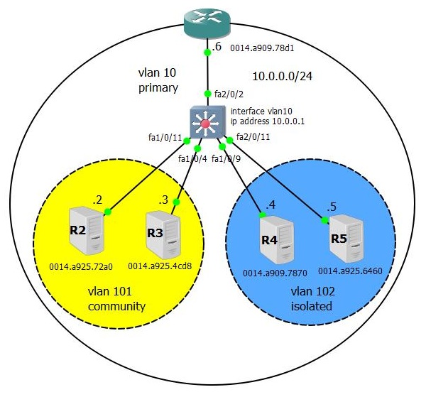
First we create 2 minor VLANs, 101 community VLANs and 102 isolated VLANs. VLAN 10 we will make the main and we will tie to it minor (the order of entering commands does not matter).
Check:
Next, we need to associate ports with VLANs.
From the interface configuration mode, we first make it private vlan host (we tell it that it is an unusual port), with the second command we bind it to isolated and primary VLANs
By analogy, we configure the fa1 / 0/4 interface
We write the same thing on fa1 / 0/9 - first we tell him that he is a private vlan host and in order that he would understand that he belongs to the community vlan 102, we bind him to her, and also do not forget to tie him to the main Vlanu.
Similarly, we configure fa1 / 0/9
To the fa2 / 0/2 interface, since we want all the hosts to “see” and he “see” everyone, set the promiscuous mode and, according to the rule, assign it to the main and all secondary VLANs.
Check the port association:
The next step is optional, we create L3 SVI, to check that isolated and community hosts can “see” it in the same way as promiscuous port.
And now the most interesting thing is how it all works .
Take a look at the table of MAC-addresses on the switch, it looks unusual. It turns out that the MAC addresses of the hosts on the ports from which they were received are simultaneously associated with the primary and secondary VLANs!
Why are hosts R4 and R5 in isolated vlan 102 not able to “see” anything except the router interface? Please note that the MAC addresses of these hosts are within 102 isolated vlan switches, marked as BLOCKED, while the MAC address of the promiscuous router interface is within vlan 102, just like regular DYNAMIC.
Now let's see why the router interface, labeled how promiscuous can “communicate” with all interfaces, is that it can see them through the primary VLAN 10 (the first 5 lines in the table of MAC addresses).
In the next article we will consider the subtleties of scalability of private VLANs, both between switches supporting this technology and on / through regular switches, which even do not know such a thing as a private VLAN (no, there is no double frame tagging) and types of special trunks .
First, remember what VLANs are. VLAN is a separate subnet, a separate Broadcast domain, used for logical network segmentation, restriction of the broadcasting domain, security, etc.
Typically, a network is divided into VLANs, then using a router-on-the-stick or multi-level switch (any device of level 3), routing is enabled (all traffic is allowed), and then, using access control lists, it is prescribed to whom, with whom and the protocol is allowed to communicate (or traffic control is applied based on the requirements of your organization’s security policy, as it would have been written in a Cisco tutorial).
')
But what to do when, for example, the network is already divided, segmented, but it became necessary to isolate servers or groups of hosts from each other?
Cisco, like other vendors, has additional tools to help limit the forwarding of traffic between hosts that are within the same subnet or control traffic within a VLAN. For this, private VLANs (private VLANs), VLAN access list and protected ports are most often used.
It should be noted that Private VLANs on Cisco are supported on Nexus models, as well as Catalyst starting at 3560 and up .
First example.
On junior models switches there is such a thing as private vlan edge . It is configured very simply - from the configuration mode of the interface we write the command (config-if) #switchport protected, as a result, the hosts connected to these ports will be isolated from each other at level 2 (that is, physically they will be connected to one switch, be on the same subnet, but will not “see” each other, while all other hosts will “see”. One of the drawbacks of this mechanism is that it has a local value for the switch and does not scale (if we connect switch A and switch B with a trunk, for example, then the protected port of the switch A can “see” the protected port of the switch B).
Let us dwell in more detail on private VLANs. The main purpose of the article is to teach how to configure private VLANs, understand the terminology, as well as get a general idea of where to use them.
The second example.
In the first example, the network is already divided into VLANs, but all of a sudden, host isolation was required, what should I do? You will say that everything is very simple: we move the hosts that need to be isolated into separate VLANs, we enable routing, we isolate them from each other using access control lists. To do this, simply create a few more subnets and that's it. But, suddenly, you work in an organization where there is a very strict hierarchy of IP addressing and it is not so easy to get another private subnet or you do not have free VLANs?
| VLAN Support Matrix for Catalyst Swithes | ||
| Type of Switch | Maximum No. of VLANs | VLAN IDs Range |
| Catalyst 2940 | four | 1-1005 |
| Catalyst 2960/2955 | 250 | 1-4094. |
| Catalyst 2960 | 255 | 1-4094. |
| Catalyst 2970/2550/3560/3750 | 1005 | 1-4094. |
| Catalyst 2848G / 2980G / 4000/4500 | 4094 | 1-4094. |
| Catalyst 6500 | 4094 | 1-4094. |
Fig. - Isolation of servers in the DMZ.
The third example.
You work in a provider and provide web hosting services for a large number of clients, you put web servers on the same network, and it turns out that there is no isolation, they can all “hear” each other’s broadcasts, i.e. pass traffic without filtering through the firewall. If the hacker can get on one of the servers, he can deploy the attack on all servers, “put” the entire server farm. And, of course, customers want to isolate their servers from each other. Especially PVLANs are relevant for providers providing layer 2 connections as a type of service, for client separation, client And of course, he doesn’t want his broadcast to reach client B, you know what security hole is opening here. The traditional way out of the process of adding a new VLAN will not work here (method one VLAN per client), “we rest” on the scalability of the maximum number of VLANs 4094 minus the reserved ones. The second problem is VLAN is a separate subnet, you need to do subnetting and throw back another 2 addresses on each subnet (subnet and broadcast) pity, since these are “white” addresses :).
In these situations, private VLANs come to the rescue .
A bit of terminology. Private VLANs are divided into:
- Primary - the main, main VLAN
- Secondary - secondary VLANs (there are 2 types of isolated and community), all of them must belong to the primary VLAN
Ports are divided into:
- Promiscuous - this port “sees” everything and it “sees” everything, should be tied to the primary and all secondary VLANs.
- Private vlan host can belong to:
- Isolated VLAN- “sees” only a promiscuous port, does not “see” other ports even in its isolated vlan. Must be bound to its isolated VLAN and primary VLAN
- Community VLAN- “sees” only the ports in the given community vlan, to which it belongs, and the promiscuous port. Must be tied to its community VLAN and primary VLAN.
General rules
Only one isolated vlan can be bound to one promiscuous port. If you want a few isolated vlan, then each vlan should be associated with a separate promiscuous port.
Usually, only one isolated vlan is created, no matter how many hosts there are, they will still not see each other.
Unlike isolated VLAN, several VLAN communities can be tied to one promiscuous port.
Consider the following topology:
- All devices are on the same subnet 10.0.0.0/24 VLAN 10.
- R4 and R5 must be isolated from each other and R2, R3 - i.e. should have access only to the router interface.
- R2 and R3 should be isolated from R4, R5, but see each other and the router.
First we create 2 minor VLANs, 101 community VLANs and 102 isolated VLANs. VLAN 10 we will make the main and we will tie to it minor (the order of entering commands does not matter).
SW1 (config)# vlan 101 private-vlan community ! vlan 102 private-vlan isolated ! vlan 10 private-vlan primary private-vlan association 101-102 Check:
SW1#sh vlan private-vlan Primary Secondary Type Ports _ _ _ _ _ _ _ _ _ _ _ _ _ _ _ _ _ _ _ _ _ _ _ _ _ _ _ _ _ _ _ _ _ _ _ _ _ _ _ _ _ _ _ _ _ _ _ _ _ _ 10 101 community 10 102 isolated Next, we need to associate ports with VLANs.
From the interface configuration mode, we first make it private vlan host (we tell it that it is an unusual port), with the second command we bind it to isolated and primary VLANs
interface FastEthernet1/0/11 description SW1 <-> R2 switchport private-vlan host-association 10 101 switchport mode private-vlan host spanning-tree portfast end By analogy, we configure the fa1 / 0/4 interface
interface FastEthernet1/0/4 description SW1 <-> R3 switchport private-vlan host-association 10 101 switchport mode private-vlan host spanning-tree portfast end We write the same thing on fa1 / 0/9 - first we tell him that he is a private vlan host and in order that he would understand that he belongs to the community vlan 102, we bind him to her, and also do not forget to tie him to the main Vlanu.
interface FastEthernet2/0/2 description SW1 <-> R6 switchport private-vlan mapping 10 101-102 switchport mode private-vlan promiscuous Similarly, we configure fa1 / 0/9
interface FastEthernet2/0/11 description SW1 <-> R5 switchport private-vlan host-association 10 102 switchport mode private-vlan host spanning-tree portfast To the fa2 / 0/2 interface, since we want all the hosts to “see” and he “see” everyone, set the promiscuous mode and, according to the rule, assign it to the main and all secondary VLANs.
interface FastEthernet2/0/2 description SW1 <-> R6 switchport private-vlan mapping 10 101-102 switchport mode private-vlan promiscuous Check the port association:
SW1#sh vlan private-vlan Primary Secondary Type Ports _ _ _ _ _ _ _ _ _ _ _ _ _ _ _ _ _ _ _ _ _ _ _ _ _ _ _ _ _ _ _ _ _ _ _ _ _ _ _ _ _ _ _ _ _ _ _ _ _ _ 10 101 community Fa1/0/4, Fa1/0/11, Fa2/0/2 10 102 isolated Fa1/0/9, Fa2/0/2, Fa2/0/11 The next step is optional, we create L3 SVI, to check that isolated and community hosts can “see” it in the same way as promiscuous port.
SW#sh run int vlan 10 | beg int interface Vlan10 ip address 10.0.0.1 255.255.255.0 private-vlan mapping 101-102 end SW#sh int vlan 10 private-vlan mapping Interface Secondary VLANs _ _ _ _ _ _ _ _ _ _ _ _ _ _ _ _ _ _ _ _ _ _ _ _ _ _ _ _ _ _ _ _ _ _ _ vlan 10 101,102 SW1# And now the most interesting thing is how it all works .
Take a look at the table of MAC-addresses on the switch, it looks unusual. It turns out that the MAC addresses of the hosts on the ports from which they were received are simultaneously associated with the primary and secondary VLANs!
Why are hosts R4 and R5 in isolated vlan 102 not able to “see” anything except the router interface? Please note that the MAC addresses of these hosts are within 102 isolated vlan switches, marked as BLOCKED, while the MAC address of the promiscuous router interface is within vlan 102, just like regular DYNAMIC.
Now let's see why the router interface, labeled how promiscuous can “communicate” with all interfaces, is that it can see them through the primary VLAN 10 (the first 5 lines in the table of MAC addresses).
SW#sh arp Protocol Address Age (min) Hardware Addr Type Interface Internet 10.0.0.2 8 0014.a925.72a0 ARPA Vlan10 pv 101 Internet 10.0.0.3 5 0014.a925.4cd8 ARPA Vlan10 pv 101 Internet 10.0.0.1 - 0014.a98c.87c1 ARPA Vlan10 Internet 10.0.0.6 70 0014.a909.78d1 ARPA Vlan10 Internet 10.0.0.4 4 0014.a909.7870 ARPA Vlan10 pv 102 Internet 10.0.0.5 4 0014.a925.6460 ARPA Vlan10 pv 102 SW#sh mac-address-table Mac Address Table _ _ _ _ _ _ _ _ _ _ _ _ _ _ _ _ _ _ _ _ _ _ _ _ Vlan Mac Address Type Ports _ _ _ _ _ _ _ _ _ _ _ _ _ _ _ _ _ All 0100.0ccc.cccc STATIC CPU .... 10 0014.a909.7870 DYNAMIC pv Fa1/0/9 10 0014.a909.78d1 DYNAMIC Fa2/0/2 10 0014.a925.4cd8 DYNAMIC pv Fa1/0/4 10 0014.a925.6460 DYNAMIC pv Fa2/0/11 10 0014.a925.72a0 DYNAMIC pv Fa1/0/11 101 0014.a909.78d1 DYNAMIC pv Fa2/0/2 101 0014.a925.4cd8 DYNAMIC Fa1/0/4 101 0014.a925.72a0 DYNAMIC Fa1/0/11 102 0014.a909.7870 BLOCKED Fa1/0/9 102 0014.a909.78d1 DYNAMIC pv Fa2/0/2 102 0014.a925.6460 BLOCKED Fa2/0/11 SW1# In the next article we will consider the subtleties of scalability of private VLANs, both between switches supporting this technology and on / through regular switches, which even do not know such a thing as a private VLAN (no, there is no double frame tagging) and types of special trunks .
Source: https://habr.com/ru/post/165195/
All Articles