Does the AVR USB Programmer not work? Set up
The programmer does not work
This article is written for those who are just starting to learn how to program microcontrollers.
Microcontrolling gurus have nothing to do here, but for beginners who are faced with problems from China. Or the ridiculous packaging of ready-made programmers or people taking the first step in radio electronics, this article can be very, very useful. I will also describe the troubleshooting methods that I encountered myself. Not all people have an excerpt, the more the Internet is created for this, that would share the experience, is not it?
AVR programmer does not work - thousands of requests in Yandex and Google. USB asp does not work - even more. Hundreds of sites, on which you get and everywhere you read the same thing, as someone collects another programmer, but no one, I repeat, no one writes why your personal device does not work.
Fast decision. For those who do not want to read the entire post, and for a quick hand came to find a solution, I post this picture. I post changes made by me and not described on any site.
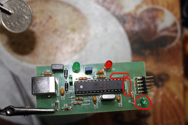
Description and details will be below.
Purchase and appearance
Visiting the radio market in our city, I stumbled upon the designer of Radio Kit - the analogue of the famous Radio Cat. Having bargained with dear madam, I bought this miracle for 65 Ukrainian tugriks - $ 8.2. Here is a photo.

')
Then it was necessary to collect and solder all this - the good is this thing I love, and it took half an hour - an ration for soldering.
So. We collected everything that was in the package, soldered according to the instructions - we got a USBasp programmer. We connect it to the computer and oh my God - Unknown device. Search "USBasp programmer unknown device" and get hundreds of discussions on the forum, where the same as me deceived or young and inexperienced users who want to start programming microcontrollers are ambushed. Horror. Once again, are we checking everything is properly welded and have we not joined together the two legs of the AtMega8 controller? Not? Are all the chips properly soldered? We will not dwell on this nonsense, because if so, then you should download the encyclopedia of a young radio amateur and read. As I did in my time. But my programmer was perfect. With a multimeter I rang every track and found no problems! And he began to search the Internet for an answer. Especially since I'm not new to this business. In 2005, I first encountered programming PIC controllers for satellite maps. Even dug up the ancient programmer UNIPROG 2003. Here are pictures - a rarity. Worked like a clock. I was still a schoolboy, and so many cards changed.
You take out the controller from the card, insert it into a special card with a bridge, insert the card into the programmer, and PonyProg works wonders on 700m tseleron. You insert the card back into the tuner - the channels are decoded. Miracle of technology was at that time. Here is a photo.


Solution to the problem
The fact is that in the instructions and on all the sites where this programmer is advertised - it is advised not to put the jumper - jumper JP3 - in my instruction it is written: “The jumper should be set in case of flashing the internal controller ATMega8” I have sinned the controller is not flashed. And the seller simply put a clean chip in the bag. But after a couple of hours, when I began to look for a space or a break in the board, I noticed small stripes and four holes connecting the 20th and 4th legs of Megi8.
SCK exit and Megi8's 19th leg.
Why so, you will soon understand. Here are screenshots with circled places.

As you noticed on the first and previous picture - in addition to two jumpers, I also circled the jumper. In the set, I repeat, there was no jumper or jumper. It had to be bought separately, the price is 5 UAH for 40 cells. The jumper was in the old motherboard. I repeat in the instructions and the scheme - it is not necessary. But having understood the circuit you understand that the programmable chip does not receive power + 5V. Very careless mistake manufacturers. Solder the jumper and close the jumper.
Carefully study the main operation of the chip. Main legs:
1 leg - RESET
17th - MOSI
18z - MISO
19 - SCK
20 - AVCC (in the instructions for the programmer was called as VTG)
RESET - MINUS and VCC - PLUS (correct if I'm wrong)
On one site, I read that when programming chips, power must be connected to all VCC legs (AVCC)
How does the programmer work
The stupidest and most important question that arose among me and hundreds of other newbies on the Internet who bought a microcontroller, say ATTINY2313 and a programmer - what next? And this question is also not enough answers in the network. Very few photos of a real working scheme. Especially for the inexperienced, just starting to get acquainted with this amazing world a couple of photos, what else is needed to flash the chip:

As you see in the photo we need the following:
-Cable connecting USBasp programmer with the controller itself (in the photo it is on board with a quartz oscillator (the chip already has its own generator)
The fee is collected under the article from the site Simple debugging board for AVR ATTiny2313 devices with quartz


-As you understand, what would be the outputs from the programmer MOSI, MISO, USCK, VCC (VTG) and RESET connected to the outputs on the tuning board, where the programmable chip is installed. On many ATMEL controllers, the 1st leg of the RESET is opposite - 4 legs in a row (from top to bottom, from 20th to 17th) go VCC, SCK, MISO, MOSI. That is, ATTINY2313 has 20 VCC, 19 USCK, 18-MISO, 17-MOSI.
Connect the output on the programmer and the board with the installed chip, respectively.
If you want to know the location and pinout of the chip - you can download DATASHIT of any controller from the site alldatasheet.com Here is the datasheet on ATTINY2313
In TINY13 and in 2313 and in MEGE8, the same pinout for software ISP programming. Only the power will have to be changed on the board. But not for every controller. For example, TINY13 - also works perfectly without quartz on the same board as I did under the article for 2313. MOSI MISO SCK VCC RESET in the same places. So one board is enough for testing so far.
Afterword
After the done manipulations. Measurements of the feeder to the board from the power programmer. After I figured out each leg and soldered the third jumper, my programmer finally worked. It was determined by the computer after soldering two metal tracks - as libusb-win32 devices. But did not want to work.
Extreme Burner wrote "Cannot Comunicate with TargetChip". I will not write how many methods I used when I thought that the problem in the drivers was a hundred. They even advised to enter safe mode and install a program for signing drivers - but it was defined as an unknown device. That decided, but did not work. Who did you understand the exact same problem, right?
And on all circuits JP3 - ONLY for flashing the internal chip. This is true. But the power through it is necessary to apply to the programmable board.
I will repeat the GURU - this article is for beginners. If you can supplement the article, or correct it, I will be only too happy, because I myself am still a novice. But a lot of people could not really answer this problem in any of the forums. I even read all the English-speaking forums.
Even soldered the programmer Gromov. But that money has already been spent - you need to bring to mind. This article is dedicated to them. Thanks for attention
Source: https://habr.com/ru/post/165029/
All Articles