Wireless data transmission, ISM range
Recently, Habré has described many examples of the implementation of weather thermometers, information collection systems, control in smart home systems - both wired, transmitting information via Ethernet, and wireless, via WiFi ™. In each case - there is a specificity, there are pros and cons. And in this article we will discuss another way to transfer data - transmission in the ISM-band at 868 MHz.
In the Russian Federation, the unlicensed range of frequencies that can be used without obtaining the permission of the SCRF, subject to the requirements for bandwidth, radiated power and purpose of the finished product, include:
- 433.075—434.750 MHz
- 868.0—868.2 MHz
- 868.7—869.2 MHz
- 2400.0—2483.5 MHz
In short, for 434 MHz, the transmitter power should be no more than 10 mW, for 868.0–868.2 MHz - up to 10 mW, for 868.7—869.2 MHz - up to 25 mW, for 2.4 GHz - no more than 100 mW. For more information about restrictions, see “ Decree of the Government of the Russian Federation of October 12, 2004 N 539“ On the procedure for registration of radio-electronic means and high-frequency devices ”.
The main difference between these ISM bands is determined by the frequency of the radiation and, as a consequence, the properties of radio waves. With regard to the task - data collection, wireless control and monitoring systems, the most optimal solution is to use the 868 MHz band. Compared to the 2.4 GHz microwave range, the longer wavelengths of 868 MHz have a lower attenuation intensity, a correspondingly higher permeability through the obstacles and the signal transmission distance is much higher. For example, a brick wall 89 mm thick absorbs about 3.5 dB of wave power at 868 MHz and 6 dB at 2.4 GHz. Also in comparison with the range of 433 MHz, 868 MHz has a lower frequency load, which contributes to more reliable operation of the radio channel.
| Maximum thickness of an obstacle through which a radio signal can pass | ||
| Frequencies | Brick wall, m | Concrete, m |
| 434 MHz | 4.3 | 0.47 |
| 868 MHz | 2.18 | 0.24 |
| 2.4 GHz | 0.78 | 0.09 |
The next important feature is the data transfer rate. Modern ISM transceivers have quite high rates, on average, this value is from 256 to 1000 kbit / s, which is quite enough for this kind of task.
')
Thus, we can conclude that in the aggregate of such parameters as - high permeability, less busy frequency range, as well as a fairly high data transfer rate, 868 MHz radio waves is the most optimal solution for this kind of problem compared to the rest of the ISM range.
For an example of data transmission in the ISM-range, we will assemble a reading device from remote sensors. Let's say it will be temperature and humidity. Those. we need to collect 2 spaced devices - the first will play the role of the head and display summary information, and the second - the sensor will periodically take measurements and send data to the head device. Moreover, both devices will be placed out of line of sight, in two different buildings.
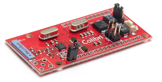
As a platform that allows you to organize a radio channel 868 MHz, we will use the Kolibri shawl (Arduino Mini + RF). It uses an EZRadioPRO Si4431 transceiver with a programmable output power from -8 to + 13dbM, which corresponds to the standards of GKRCH (20 mW). 3dbM setup step. Receiver sensitivity –121 dBm. The power consumption is 18.5 mA for reception and 30 mA for transmission. Permissible board power from 5V or 3.3V. The data transfer rate is 0.123 - 256 kbps. In addition, the board is software compatible with the Arduino IDE, which makes it easy to program. Schematic diagram .
To measure humidity and temperature, we use a digital sensor SHT10 . It is quite compact and requires minimal strapping. The accuracy of measuring temperature readings is ± 0.5, and humidity 4.5%. Datashit .
To display information on the head unit, we take a graphic LCD display with a resolution of 128 * 64 pixels ( WG12864A-TGH-VNW ). The backlight is white, the dot color is gray. And, in order not to occupy all the pins of the microcontroller under the display, we will connect it via SPI using the MCP23S17 microcircuit. But more on that later.
| Key system components | |
| For head unit | For remote sensor |
| "Iron" | |
|
|
| Soft | |
Head device
1. Build
To begin with we will collect the scheme of the head device
The head unit will consist of a Hummingbird board, which will receive and display data on the LCD. And as mentioned above, we will work with the LCD display through the SPI interface, using the MCP23S17 chip.

This scheme will collect on the breadboard. The terminals marked with blue lines are connected to the Hummingbird board - these are digital contacts 10, 11, 12, 13 (SPI). On the prototyping board and on the Hummingbird it remains to supply 5V power. Power supply of the device is assumed either from the power supply, where the “honest” is 5V, or through a linear stabilizer.

2. Firmware
To work with the Kolibri board radio module, we will use the ready-made EZRadioPRO library under the Arduino IDE. It needs to be downloaded and installed inside the IDE. We also need the I2C_graphical_LCD_display library for working with the LCD display. It also needs to be downloaded and installed.
We start the Arduino IDE and create a sketch like this based on an example.
#include <SI4431.h> #include "SimRF.h" #include <Wire.h> #include <SPI.h> #include <I2C_graphical_LCD_display.h> I2C_graphical_LCD_display lcd; // (0 ) #define LOCAL_ADDR (0) // 1: #define RF_FUNC01 (1) // 2: #define RF_FUNC02 (2) // unsigned char RFTX_buffer[32]; // unsigned char RFRX_buffer[32]; char i2a_buf[6]; /* 4- 16- */ typedef struct { u16 Register0; u16 Register1; u16 Register2; u16 Register3; } tRemoteSensor; tRemoteSensor RemoteSensorStatus[2]; // 1 2 tRemoteSensor RemoteSensorCmd[2]; // 1 2 void print_P (const char* s) { char c; while ((c = pgm_read_byte(s++)) != 0) Serial.print(c); } u8 get_xor(u8* Src, u8 len) { u8 xoracc = 0; while (len--) { xoracc ^= *Src++; } return xoracc; } // 02 RemoteSensorCmd[]; void RFTX_FUNC02(u8 addr) { RemoteSensorCmd[addr -1].Register0 = RemoteSensorStatus[addr -1].Register0; RemoteSensorCmd[addr -1].Register1 = RemoteSensorStatus[addr -1].Register1; RemoteSensorCmd[addr -1].Register2 = RemoteSensorStatus[addr -1].Register2; RemoteSensorCmd[addr -1].Register3 = RemoteSensorStatus[addr -1].Register3; RFTX_buffer[0] = addr; // RFTX_buffer[1] = LOCAL_ADDR; // RFTX_buffer[2] = RF_FUNC02; // 02 u16* p16 = (u16*) &RFTX_buffer[3]; *p16++ = RemoteSensorCmd[addr -1].Register0; *p16++ = RemoteSensorCmd[addr -1].Register1; *p16++ = RemoteSensorCmd[addr -1].Register2; *p16++ = RemoteSensorCmd[addr -1].Register3; // RFTX_buffer[11] = get_xor ((u8*)RFTX_buffer, 11); // /*print_P(PSTR("\r\nData to TX: ")); for (u8 i = 0; i< 12; i++) { Serial.print((u8)RFTX_buffer[i], HEX); print_P(PSTR(",")); }*/ SI4431.TXData((u8*) RFTX_buffer, 12); } void RFRX_FUNC01(u8 SlaveAddr, u16* Payload) { RemoteSensorStatus [SlaveAddr - 1].Register0 = *Payload++; RemoteSensorStatus [SlaveAddr - 1].Register1 = *Payload++; RemoteSensorStatus [SlaveAddr - 1].Register2 = *Payload++; RemoteSensorStatus [SlaveAddr - 1].Register3 = *Payload++; } /** * : * addr - * len - * pData - SRAM * : * (0..127) * -1 */ void RFRX_MASTER_PROCESS(u8 len) { s8 funccode; u8 SlaveAddr; // if (len < 3) return; //print_P(PSTR("\r\n Dump:")); /*for (u8 i = 0; i< len; i++) { Serial.print(RFRX_buffer[i], HEX); print_P(PSTR(",")); i2a((u16)RFRX_buffer[i], i2a_buf); lcd.string(i2a_buf); lcd.string("-"); } */ SlaveAddr = RFRX_buffer[1]; // if ((RFRX_buffer[0] == LOCAL_ADDR)&&(SlaveAddr != LOCAL_ADDR)) { // MASTER SLAVE ( >= 1) // XOR // print_P(PSTR("\r\n Correct Addr!")); if (get_xor((u8*)RFRX_buffer, len - 1) == (u8) RFRX_buffer[len-1]) { funccode = RFRX_buffer[2]; // switch (funccode) { case RF_FUNC01: { // //print_P(PSTR("\r\nData from sensor: ")); //Serial.print(SlaveAddr, HEX); tRemoteSensor* pSensorData = (tRemoteSensor*)&RFRX_buffer[3]; // // s16 Temperature_x100 = (s16) (pSensorData-> Register0); u16 Humidity_x100 = pSensorData-> Register1; u16 Data1 = pSensorData-> Register2; u16 Data2 = pSensorData-> Register3; // lcd.gotoxy (0, 16); lcd.string("Temperature: "); lcd.gotoxy (80, 16); if (Temperature_x100 < 0) { lcd.string("-"); Temperature_x100 = -Temperature_x100;// } u16 Temp = Temperature_x100 / 100; // i2a(Temp, i2a_buf); showString(i2a_buf); //lcd.string(i2a_buf); showString("."); i2a(Temperature_x100 - Temp * 100, i2a_buf); // showString(i2a_buf); lcd.string("C "); // lcd.gotoxy (0, 32); lcd.string("Humidity: "); lcd.gotoxy (80, 32); Temp = Humidity_x100 / 100; i2a(Temp, i2a_buf); showString(i2a_buf); showString("."); i2a(Humidity_x100 - Temp * 100, i2a_buf); showString(i2a_buf); lcd.string("% "); // //i2a(Data, i2a_buf); //lcd.string(i2a_buf); // 01 02 if (SlaveAddr <= 0x02) { RFRX_FUNC01(SlaveAddr, (u16*) &RFRX_buffer[3]); } // 500 delay (500); // 02 RFTX_FUNC02(SlaveAddr); } break; case RF_FUNC02: { // // - , print_P(PSTR("\r\nACK from sensor:")); Serial.print(SlaveAddr, HEX); } break; default: break; } } else print_P(PSTR("\r\n XOR error!")); } else print_P(PSTR("\r\n ADDR error!")); } // 01 void RFRX_RESP_FUNC02(t_cmd_servo* pcmd_servo) { s16 POS1, POS2, POS3, POS4; POS1 = pcmd_servo->POS1; POS2 = pcmd_servo->POS2; POS3 = pcmd_servo->POS3; POS4 = pcmd_servo->POS4; /*print_P(PSTR("\r\nServo function response OK!")); print_P(PSTR("\r\nPOS1:")); Serial.print(POS1, HEX); Serial.print(POS2, HEX); Serial.print(POS3, HEX); Serial.print(POS4, HEX); */ } void setup(){ u8 ItStatus1, ItStatus2; lcd.begin(0x20, 0, 10); Serial.begin(38400); u8 length; u8 temp8; delay (1000); SI4431.begin(); // , SPI /*for (u8 reg = 0; reg <=0x7f; reg++) { print_P(PSTR("\r\nReg:")); u8 c = SI4431.ReadRegister(reg); Serial.print(reg, HEX); print_P(PSTR(", ")); Serial.print(c, HEX); }*/ SI4431.Init(7); lcd.gotoxy(36, 0); lcd.string("I'm Ready!"); } void loop(){ u8 ItStatus1, ItStatus2; u8 len; // 2 : // a) : 'ipkval' // ) CRC: 'icrcerror' SI4431.RXIRQEnable(); // NIRQ SI4431.ReadStatus(&ItStatus1, &ItStatus2); /* */ SI4431.RXEnable(); // // , CRC if(SI4431.IRQstate() == 0 ){ // SI4431.RXDisable(); // NIRQ SI4431.ReadStatus(&ItStatus1, &ItStatus2); // CRC if( (ItStatus1 & 0x01) == 0x01 ){ print_P(PSTR("\r\n Received CRC Error!")); // FIFO SI4431.FIFOReset(); // /*TX_LED_SET RX_LED_SET delay(500); TX_LED_CLR RX_LED_CLR*/ } // if( (ItStatus1 & 0x02) == 0x02 ){ print_P(PSTR("\r\n Received good packet! Len = ")); // len = SI4431.RXPacketLen(); Serial.print(len, HEX); //, if(len <= sizeof(RFRX_buffer)) { SI4431.RXData((u8 *)RFRX_buffer, len); // RFRX_MASTER_PROCESS (len); } } // RX FIFO SI4431.FIFOReset(); // SI4431.RXEnable(); } } void i2a( unsigned int i, char* pOut_buf ){ int ii; char int_buf[5]; for (ii=0; ii < 5; ){ int_buf[ii++] = '0'+ i % 10; i = i / 10; } do{ ii--; }while( (int_buf[ii] == '0') && (ii != 0) ); do { *pOut_buf++= int_buf[ii--]; } while (ii >= 0); *pOut_buf = 0x00; } This sketch initializes the radio channel, the head unit is assigned the address 0. The maximum transmitter power is set to 13dBm: SI4431.Init (7);
In this example, readings from 1 remote sensor are displayed, if necessary, you can display readings from a variety of sensors in the same way.
Next, the firmware needs to be loaded into the Hummingbird board. This can be done in several ways.
- With the Arduino board
- Using USB-Serial Converter
- With the help of an in-circuit programmer.
For firmware using Arduino, you first need to extract a microcontroller from it. After that you need to connect both boards with the following pins:
| Arduino | Hummingbird |
| Pin 0 | Pin 0 |
| Pin 1 | Pin 1 |
| RESET | RESET |
| + 5V | + 5V |
| GND | GND |
After you have connected and set the power jumper to the 5V position on the Hummingbird, you can connect Arduino to the PC. In the Arduino IDE, specify the correct port and in the Tools -> Board section, select the “Arduino Nano w / Atmega 168” option, and then click on the “Download” button.
Similar actions are taken when booting with a USB-Serial converter. Well, the easiest way is to download using the programmer. In the Arduino IDE, click the “Compile” button, then “find” the hex file with the firmware. You connect the programmer to the ICSP Hummingbird connector, apply power to the board, load the firmware into it, specifying in the shell of your programmer MK ATMEGA168A. Fuses: 0xF8, 0xDF, 0xFF. Lockbit: 0xCF.
Flashed, disconnected all the extra wiring from the hummingbird. Now we serve on the power board and the inscription should appear on the LCD: I'm Ready! The head unit is assembled, go to the next step.
Sensor
1. Build
The board with the sensor will consist of only one digital sensor. The board power will be battery, 3V.
Sensor circuit SHT10.

Let's collect according to the scheme on the breadboard. The sensor is connected to the Hummingbird by 4 wiring (digital pins 6 and 7 and power).

Before you connect the battery compartment to the hummingbird, you must download the firmware. And after that we connect the battery compartment to the Hummingbird to the 3V power connector and also set the jumper to the 3V position.
A few words about nutrition. If the sensor is to be used outdoors, then the appropriate batteries must be used. The most frost-resistant batteries are lithium-thionyl-chloride (LiSOCl2), lithium-iron-phosphate (LiFePO4).
2. Firmware
In addition to the EZRadioPRO library, you will need the SHT1x library for the sensor, with its help we will read the temperature and humidity readings. Download and install this library.
We start the Arduino IDE and create a sketch like this based on an example.
#include <SI4431.h> #include "SimRF.h" #include <avr/sleep.h> #include <avr/wdt.h> #include <SHT1x.h> #define dataPin 7 #define clockPin 6 SHT1x sht1x(dataPin, clockPin); //#define DEBUG_MODE // (0 ) #define SLAVE_ADDR (1) // // 1: #define RF_FUNC01 (1) // 2: #define RF_FUNC02 (2) // unsigned char RFTX_buffer[32]; // unsigned char RFRX_buffer[32]; unsigned char putch(unsigned char send_char) { while (!(UCSR0A & 0x20)); UDR0 = (unsigned char) send_char; while (!(UCSR0A & 0x20)); return(send_char); } /* FLASH */ void print_P (const char* s) { char c; while ((c = pgm_read_byte(s++)) != 0) putch(c); } /* XOR u8* Src - u8 len - */ u8 get_xor(u8* Src, u8 len){ u8 xoracc = 0; while (len--){ xoracc ^= *Src++; } return xoracc; } /* 01 u8 addr - u8* Data - u8 Len - */ void RFTX_FUNC01(u8 addr, u8* Data, u8 Len){ RFTX_buffer[0] = addr; // RFTX_buffer[1] = SLAVE_ADDR; // RFTX_buffer[2] = 0x01; // 01 // for (u8 i = 0 ; i < Len; i++){ RFTX_buffer[3+i] = *Data++; } // XOR RFTX_buffer[3 + Len] = get_xor ((u8*)RFTX_buffer, Len + 3); SI4431.TXData((u8*) RFTX_buffer, 3 + Len + 1); // } /** * : * addr - * len - * pData - SRAM * : * (0..127) * -1 */ s8 RFRX_PROCESS(u8 addr, u8 len, u8* pData){ s8 funccode; // if (len < 3) return -1; if ((RFRX_buffer[0] == SLAVE_ADDR)&&(RFRX_buffer[1] == addr)) { // if (get_xor((u8*)RFRX_buffer, len - 1) == RFRX_buffer[len-1]){ funccode = RFRX_buffer[2]; pData = (u8*) &RFRX_buffer[3]; return funccode; } else return -1; } else return -1; } /* 02 u8* PayloadData - u8 PayloadLen - */ void RFRX_RESP_FUNC02(u8* PayloadData, u8 PayloadLen){ // #ifdef DEBUG_MODE for (u8 i = 0; i< PayloadLen; i++){ Serial.print(*PayloadData++, HEX); } #endif } // void RFTX_ACK_FUNC02(u8 addr, u8* Data, u8 Len){ RFTX_buffer[0] = 0x00; // RFTX_buffer[1] = SLAVE_ADDR; // RFTX_buffer[2] = RF_FUNC02; // for (u8 i = 0 ; i < Len; i++){ RFTX_buffer[3+i] = *Data++; } // XOR RFTX_buffer[3 + Len] = get_xor ((u8*)RFTX_buffer, Len+3); SI4431.TXData((u8*) RFTX_buffer, 3 + Len + 1); // } u16 SensorData [4]; // 4 16 volatile unsigned char WDT_wake; volatile unsigned char SLEEP_TIME = 15; //volatile unsigned char WDT_counter; // /* */ ISR(WDT_vect) { static unsigned char WDT_counter; // if (WDT_counter++ == SLEEP_TIME) { WDT_counter = 0; WDT_wake = 1; } //Serial.print(WDT_counter, HEX); asm ("WDR"); } void setup_WDT(void) { asm ("CLI"); asm ("WDR"); MCUSR &= ~(1<<WDRF); // WDTCSR = (1 << WDCE)|(1<<WDE); WDTCSR = (1 << WDP2)|(1 << WDP1)|(1 << WDIE)|(1 << WDIF); // 1 . asm ("SEI"); } void off_WDT(void){ asm ("CLI"); asm ("WDR"); MCUSR &= ~(1<<WDRF); // WDTCSR = (1 << WDCE)|(1<<WDE)|(1 << WDIF); /* Turn off WDT */ WDTCSR = 0x00; asm ("SEI"); } void sys_sleep(void){ asm ("CLI"); ADCSRA &= ~(1 << ADEN); // SMCR |= (1<<SE); // power-down asm ("SEI"); asm ("SLEEP"); } void sys_wake(void){ // } void RF_sleep (void){ u8 ItStatus1, ItStatus2; // NIRQ SI4431.ReadStatus(&ItStatus1, &ItStatus2); SI4431.WriteRegister(0x08, 0x03); // FIFO SI4431.WriteRegister(0x08, 0x00); SI4431.WriteRegister(0x07, 0x00); // } void setup(){ Serial.begin(38400); delay (1000); u8 ItStatus1, ItStatus2; u8 length; u8 temp8; #ifdef DEBUG_MODE print_P (PSTR("\r\nHello!")); #endif delay (100); SI4431.begin(); #ifdef DEBUG_MODE // , SPI for (u8 reg = 0; reg <=0x7f; reg++){ print_P(PSTR("\r\nReg:")); u8 c = SI4431.ReadRegister (reg); Serial.print(reg, HEX); print_P(PSTR(", ")); Serial.print(c, HEX); } #endif SI4431.Init(7); #ifdef DEBUG_MODE print_P(PSTR("\r\nRadio initialisation is OK")); #endif delay (1000); setup_WDT(); SMCR = (1<<SE)|(1<<SM1); // power-down sys_sleep(); } void loop(){ u8 ItStatus1, ItStatus2; unsigned long Timer; if (WDT_wake){ Timer = 0; WDT_wake = 0; // N // off_WDT(); //digitalWrite(13, HIGH); // ( ) #ifdef DEBUG_MODE print_P(PSTR("\r\n WAKE UP!")); #endif // 1) , SHT11x float Temp = sht1x.readTemperatureC(); s16 Temp_x100 = (s16) (Temp * 100.0); // 100.0 SensorData[0] = (u16) Temp_x100; float Humidity = sht1x.readHumidity(); u16 Humidity_x100 = (s16) (Humidity * 100.0); // 100.0 SensorData[1] = Humidity_x100; SensorData[2] = 0; SensorData[3] = 0; // 2) , // 3) , // 4) 0 ( ... ) for (u8 TXcnt = 0; TXcnt< 4; TXcnt++) { #ifdef DEBUG_MODE print_P(PSTR("\r\n TX to MASTER #")); #endif Serial.print(TXcnt + 1, DEC); RFTX_FUNC01(0x00, (u8*) SensorData, 8); // 0 8 // 4) 0 } // 5) RX // // 2 : // a) : 'ipkval' // ) CRC: 'icrcerror' SI4431.RXIRQEnable(); // NIRQ SI4431.ReadStatus(&ItStatus1, &ItStatus2); // FIFO SI4431.FIFOReset(); /* */ SI4431.RXEnable(); // 6) 1 #ifdef DEBUG_MODE print_P(PSTR("\r\n Wait Resp")); #endif Timer = 0; #define RESP_TIMEOUT (65535 * 32) while (Timer < RESP_TIMEOUT){ //asm ("WDR"); if(SI4431.IRQstate() == 0 ) { // CRC // SI4431.RXDisable(); // NIRQ SI4431.ReadStatus(&ItStatus1, &ItStatus2); // CRC if( (ItStatus1 & 0x01) == 0x01 ) { #ifdef DEBUG_MODE print_P(PSTR("\r\n RX CRC Error!")); #endif // FIFO SI4431.FIFOReset(); // break; // } else if( (ItStatus1 & 0x02) == 0x02 ) { // #ifdef DEBUG_MODE print_P(PSTR("\r\n RX packet Len = ")); #endif // u8 len = SI4431.RXPacketLen(); #ifdef DEBUG_MODE Serial.print(len, HEX); #endif //, if(len <= sizeof(RFRX_buffer)) { SI4431.RXData((u8 *)RFRX_buffer, len); // s8 funccode = RFRX_PROCESS (0x00, len, (u8*)RFRX_buffer); switch (funccode) { case RF_FUNC02: { // ! #ifdef DEBUG_MODE print_P(PSTR("\r\n MASTER RESPONSE!")); #endif u8* PayloadData = (u8*) &RFRX_buffer[3]; // u8 PayloadLen = len - 4; // RFRX_RESP_FUNC02(PayloadData, PayloadLen); // // 7) , // for (u8 TXcnt = 0; TXcnt< 4; TXcnt++) { #ifdef DEBUG_MODE print_P(PSTR("\r\n ACK MASTER RESPONSE!")); #endif RFTX_ACK_FUNC02(0x00, PayloadData, PayloadLen); } } break; default: #ifdef DEBUG_MODE print_P(PSTR("\r\nInvalid RX packet!")); #endif break; } } } break; // } else { Timer++; } } #ifdef DEBUG_MODE if (Timer == RESP_TIMEOUT) print_P(PSTR("\r\n Response Timeout!")); print_P(PSTR("\r\n SLEEP...")); #endif // 8) RF_sleep(); setup_WDT(); //digitalWrite(13, LOW); } // 9) , N // 10) , . 1. sys_sleep(); } The scheme of this program is simple. After initialization of the radio channel, where it is assigned the address 1 and the first data transmission to the device with the address 0, the microcontroller puts the transceiver into sleep mode and then falls asleep for 15 seconds. After this time has elapsed, the watchdog timer wakes up, turns on the transceiver and transmits the data again.
A set of such sensors can be tied to a single head unit.
Load this sketch into a Hummingbird. After downloading, turn off all unnecessary, connect the battery power and turn on the power. After some time, on the head unit we will receive readings from a remote sensor.
Uh, it seems everything is written. If something is not clear, ask :)
Source: https://habr.com/ru/post/164215/
All Articles