The imposition of basic inscriptions in accordance with GOST 2.104 (frames) on LaTeX documents
Despite the fact that many consider our government standards for ESKD and ESPD obsolete, the design and program documentation must be implemented in accordance with them.
When I was a very young “specialist”, I looked with dismay at how technical conditions, programs and test methods were written in Microsoft Office. Sometimes these documents are very complex and long. The most intimidating were the basic inscriptions placed in the footer. They did not correspond to GOST 2.104. In common people they are called "frames." They were terrible. I have not seen anyone manage to make them right. Floated sizes, thickness lines. It was visible even without a ruler.
Imagine developing a software product without using any version control system. It sounds ridiculous. However, few people are confused by writing complex documents in Microsoft Office. The file format is binary, it is impossible to track any changes. Authorship of lines is not possible. It is also impossible to work with several people on the same document at the same time. Editing documents 500 pages long with a lot of pictures is almost impossible. Modern computers with a lot of RAM, of course, do it much better than they did 5 years ago.
That is why at one time I switched to LaTeX (more precisely, XeTeX). All documents immediately began to be placed in SVN. It was possible to insert vector images into the document without any problems - it looked amazing. No problem was established by the author of each line. It was even possible to write comments in the document, just like in C.
')
There was one problem. It was necessary to fit those “frames” to the documents. Maybe I was looking badly, but at that time I did not find ready-made solutions, or they did not suit me for quality. I know that LaTeX is turing-complete and that you can draw anything you want with the help of his commands. However, at that time my knowledge in C was 100 times better than in LaTeX. In fact, the transition to LaTeX was not so painless.
I was full of determination, I needed to realize my plans at all costs. I knew about the existence of pdftk. With it, you can overlay one PDF document on top of another. I just had to somehow generate a document containing only the "framework". Then I could easily put it on any PDF document.
I already loved inkscape enough. After reviewing the structure of the SVG file, I realized that generating it is not so difficult. This is a bit more complicated than generating HTML using PHP. inkscape can export SVG to PDF, including from the command line. For a couple of days I wrote a C program that generated any basic inscriptions for any design documents. It was necessary to indicate the type of the document (text or drawing), the size of the sheet, its orientation and the number of sheets. Each column of the main inscription has a number in accordance with GOST 2.104. For example, in column 11 fit the names of the persons who signed the document. I decided to store the data that should be filled in the appropriate columns in a simple text file in tabular form as a separator.
Original file:
Result of work:

A makefile was quickly written that automated the whole process. In general, the build process was as follows:
1. The required number of times is called LaTeX. As a rule, two passes are needed, very rarely three;
2. With pdftk, the number of pages (N) is extracted from a PDF file generated by LaTeX;
3. The main title generator starts. It turns out N SVG files;
4. Each SVG file is converted to PDF format using inkscape. It turns out N PDF files;
5. The resulting title block is overlaid using pdftk on the document (generated by LaTeX).
Thus obtained beautiful documents with beautiful "frames". However, there was one drawback. In order to impose a “frame” on a PDF file, its (PDF file) must first be divided into separate pages. Then, after applying, again put together. As a result, the document size increases by almost N times, where N is the number of pages. Cross-references also stopped working and content disappeared (PDF).
To solve this problem, it was necessary to implement the imposition of “frameworks” directly using LaTeX. The \ AddToShipoutPicture command came to the rescue. It allows you to put a background on the page. Everything was decided by the following piece of code:
File Form.pdf is a multi-page document with “frames”.
Now everything was great. The file size did not increase once again, the basic inscriptions looked as it should and were in the right place with the right scale.
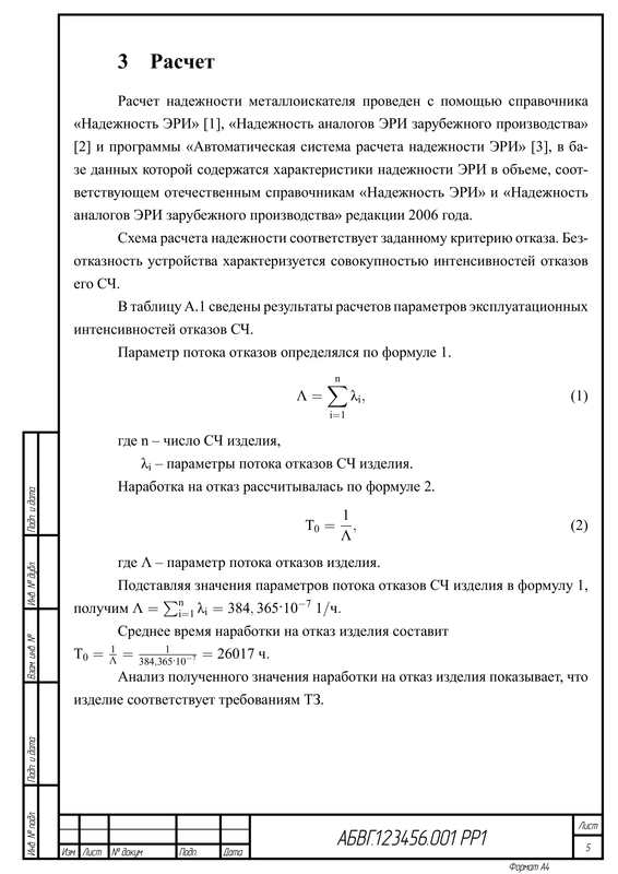
Fragment of a text document:
There are a number of text documents (GOST 2.106), which are tables. These documents include specifications and various statements. Also widely distributed are lists of items. I do not understand why these documents are drawn in AutoCAD. This takes a lot of time.
After spending a little more time, I wrote a set of small console utilities that turn a regular CSV file into a specification or a list of purchased products, for example.
An example of a generated list of items:

Everything written refers to 2009. After that, I honestly did not try to look for analogues anymore, since the solution is completely satisfactory until now. Changes, if necessary, are made easily, because everything is written with his own hand. During development, only the standard C and C ++ libraries were used. Some time even used under Windows.
As a result, the whole system of assembly of design documentation was made. The need to use any proprietary software has practically disappeared. With inkscape you can make quite complex drawings. Yes, it is not intended for this, but it is absolutely free, unlike AutoCAD, for example.
To build a package of design documentation, just go to the directory and execute make. All documents are collected and stored in a separate place. The number of sheets for each document separately and for the entire project is automatically calculated. Sometimes these numbers are very necessary, and it’s not at all interesting to count with your hands, especially when there are more than 100 documents and they change periodically.
UPD: All of the above is available in a particular approximation on GitHub: github.com/kutelev/gost_forms
UPD2: Collected examples are available at GitLab: gitlab.com/kutelev/gost_forms/builds/artifacts/master/browse?job=build%3Adocuments
When I was a very young “specialist”, I looked with dismay at how technical conditions, programs and test methods were written in Microsoft Office. Sometimes these documents are very complex and long. The most intimidating were the basic inscriptions placed in the footer. They did not correspond to GOST 2.104. In common people they are called "frames." They were terrible. I have not seen anyone manage to make them right. Floated sizes, thickness lines. It was visible even without a ruler.
Imagine developing a software product without using any version control system. It sounds ridiculous. However, few people are confused by writing complex documents in Microsoft Office. The file format is binary, it is impossible to track any changes. Authorship of lines is not possible. It is also impossible to work with several people on the same document at the same time. Editing documents 500 pages long with a lot of pictures is almost impossible. Modern computers with a lot of RAM, of course, do it much better than they did 5 years ago.
That is why at one time I switched to LaTeX (more precisely, XeTeX). All documents immediately began to be placed in SVN. It was possible to insert vector images into the document without any problems - it looked amazing. No problem was established by the author of each line. It was even possible to write comments in the document, just like in C.
')
There was one problem. It was necessary to fit those “frames” to the documents. Maybe I was looking badly, but at that time I did not find ready-made solutions, or they did not suit me for quality. I know that LaTeX is turing-complete and that you can draw anything you want with the help of his commands. However, at that time my knowledge in C was 100 times better than in LaTeX. In fact, the transition to LaTeX was not so painless.
I was full of determination, I needed to realize my plans at all costs. I knew about the existence of pdftk. With it, you can overlay one PDF document on top of another. I just had to somehow generate a document containing only the "framework". Then I could easily put it on any PDF document.
I already loved inkscape enough. After reviewing the structure of the SVG file, I realized that generating it is not so difficult. This is a bit more complicated than generating HTML using PHP. inkscape can export SVG to PDF, including from the command line. For a couple of days I wrote a C program that generated any basic inscriptions for any design documents. It was necessary to indicate the type of the document (text or drawing), the size of the sheet, its orientation and the number of sheets. Each column of the main inscription has a number in accordance with GOST 2.104. For example, in column 11 fit the names of the persons who signed the document. I decided to store the data that should be filled in the appropriate columns in a simple text file in tabular form as a separator.
Original file:
 Drawing A4
 1 0 Metal detector
 1 1 Assembly drawing
 2 0 ABCG.123456.001
 6 0 1: 1
 11 0 Ivanov
 11 1 Sidorov
 11 2 Petrov
 11 4 Sokolov
 11 5 Kuznetsov
Result of work:
A makefile was quickly written that automated the whole process. In general, the build process was as follows:
1. The required number of times is called LaTeX. As a rule, two passes are needed, very rarely three;
2. With pdftk, the number of pages (N) is extracted from a PDF file generated by LaTeX;
3. The main title generator starts. It turns out N SVG files;
4. Each SVG file is converted to PDF format using inkscape. It turns out N PDF files;
5. The resulting title block is overlaid using pdftk on the document (generated by LaTeX).
Thus obtained beautiful documents with beautiful "frames". However, there was one drawback. In order to impose a “frame” on a PDF file, its (PDF file) must first be divided into separate pages. Then, after applying, again put together. As a result, the document size increases by almost N times, where N is the number of pages. Cross-references also stopped working and content disappeared (PDF).
To solve this problem, it was necessary to implement the imposition of “frameworks” directly using LaTeX. The \ AddToShipoutPicture command came to the rescue. It allows you to put a background on the page. Everything was decided by the following piece of code:
\ifdefined\overlaypass \newcounter{overlaypage} \setcounter{overlaypage}{1} \AddToShipoutPicture{\AtPageLowerLeft{\includegraphics[page=\arabic{overlaypage}] {./Form/Form.pdf}\stepcounter{overlaypage}}} \fi File Form.pdf is a multi-page document with “frames”.
Now everything was great. The file size did not increase once again, the basic inscriptions looked as it should and were in the right place with the right scale.
Fragment of a text document:
Not at all about LaTeX
There are a number of text documents (GOST 2.106), which are tables. These documents include specifications and various statements. Also widely distributed are lists of items. I do not understand why these documents are drawn in AutoCAD. This takes a lot of time.
After spending a little more time, I wrote a set of small console utilities that turn a regular CSV file into a specification or a list of purchased products, for example.
An example of a generated list of items:
Original file
 H Chokes
 L L1 D3 - 03 - 0.16 GOST 17597 - 78 1
 L L2 D25 - 0.08 - 1.1 GOST 17597 - 78 1
 L
 H Capacitors
 L C1 KT4 - 24 - 180mkF OZHO.460.021 TU 1
 L 2  - 5 - 100µF ± 10% .460.021  1
 L 3  - 5 - 51 ± 10% .460.021  1
 L 4  - 5 - 160µF ± 10% .460.021  1
 L C5 KM - 5 - 51µF ± 10% OZHO.460.021 TU 1
 L 6, C7  - 5 - 36 μF ± 10% .460.021  2
 L 8  - 5 - 0.15 microfarad ± 10% .460.021  1
 L 9  - 5 - 200 microfarad ± 10% .460.021  1
 L 10  - 5 - 0.047 microfarad ± 10% .460.021  1
 L 11 53 - 16 - 50µF ± 20% .460.021  1
 L
 H ICs
 L DD1 K176LP2 GOST 9336-31 1
Conclusion
Everything written refers to 2009. After that, I honestly did not try to look for analogues anymore, since the solution is completely satisfactory until now. Changes, if necessary, are made easily, because everything is written with his own hand. During development, only the standard C and C ++ libraries were used. Some time even used under Windows.
As a result, the whole system of assembly of design documentation was made. The need to use any proprietary software has practically disappeared. With inkscape you can make quite complex drawings. Yes, it is not intended for this, but it is absolutely free, unlike AutoCAD, for example.
To build a package of design documentation, just go to the directory and execute make. All documents are collected and stored in a separate place. The number of sheets for each document separately and for the entire project is automatically calculated. Sometimes these numbers are very necessary, and it’s not at all interesting to count with your hands, especially when there are more than 100 documents and they change periodically.
UPD: All of the above is available in a particular approximation on GitHub: github.com/kutelev/gost_forms
UPD2: Collected examples are available at GitLab: gitlab.com/kutelev/gost_forms/builds/artifacts/master/browse?job=build%3Adocuments
Source: https://habr.com/ru/post/163315/
All Articles