Exporting polygons from Altium Designer to AutoCAD
Good day, dear Habroskoobschestvo.
In my first post, I want to describe the process of exporting Altium Designer’s PCB objects like polygons. I encountered this problem more than once during the course and diploma projects at the university. They are required to draw up documentation on ESKD, and this means that the package of documentation must include a drawing "Printed circuit boards". An experienced user will note that the drawing can also be made in Altium itself by using mechanical layers for frames, duplicating layers and transferring them, and so on. But I prefer to use AutoCAD , as a more familiar environment for the design of drawings.

')
The essence of the problem and the solution below.
Altium has a whole range of exporters, among which is an exporter in .DXF. In releases it has been around for a long time and generally works well - footprints are exported in the form of blocks or primitives, vias and pads with holes on separate layers, support for different versions of AutoCAD, the possibility of layers one by one, stacks and so on. All this works remarkably well when exporting a board trace without polygon fill objects. When trying to export something similar to the one shown in fig. 1. In .DXF you get something shown in Fig. 2
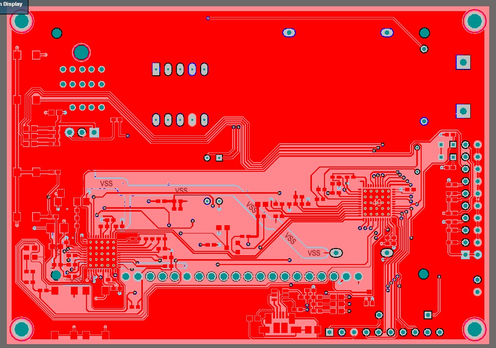
Fig. one
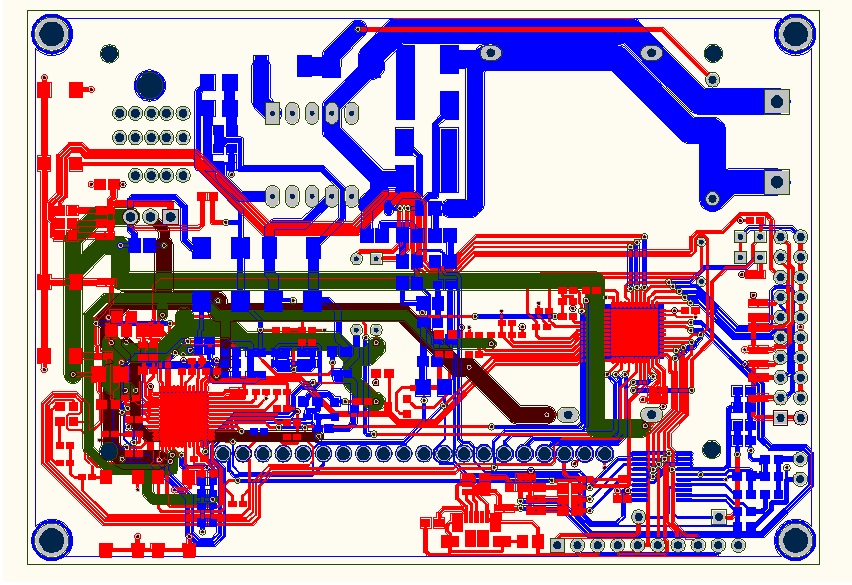
Fig. 2
The exporter, instead of polygons, transfers only their outlines. 3

Fig. 3
How to restore polygons? Being just a novice designer and having interrupted the Internet for some time that was not acceptable for solving such a task, I decided to try to solve the problem on my own. And here is my action plan as follows.
Step 1. Export proper
We do everything as usual. Go to File> Save As ... In the Save as type field, select .dwg, .dxf from the drop-down list. Next, set the export options from the window in Fig. four.

Fig. four
Here we select Metric units, vias and pads with holes on different layers, we export the seats in blocks, and in the Layers field, select the Currently Visible Layers . Then only visible layers are exported. Since for the drawing of the board I do not need mechanical and other layers, I left only Top, Bottom and 2 inner layers visible. Altium 'e board and export results to AutoCAD ' e in Figures 1 and 2 at the beginning of the post.
Step 2. Selection of areas of polygons.
Create a fill and AutoCAD is not difficult, but for this you need to select all the lines that limit it. On the original board after the export, this is problematic. So you need to figure out how to select all the lines at once. Starting to look at the picture, I noticed that the tracks, holes and contact pads are transferred with the “Polyline” line type, while the outlines of the polygons (Fig. 3) are with the “Segments” type. That was enough to use filter selection. In AutoCAD on the Main tab, we find the Utilities section and click “Quick Pick” - icon with lightning, pic. five.

Fig. five
Set the selection parameters, as in Figure 6. In this case, select all segments on the TOP LAYER layer, if necessary on the other, select another one.

Fig. 6
The result will be the selection of all the lines that limit the polygon. Press Ctrl + C and paste this contour onto the free space in the drawing - the result is in fig. 7

Fig. 7
Step 3. Fill and transfer.
Now everything is simple - create a hatching ( AutoCAD main tab, Drawing panel). From the settings dialog, select the type of hatching Solid , or any other one. Click the button "Add: select objects". Select the entire contour and press Enter. In the setup dialog click OK. It turns out our landfill - Figure 8.
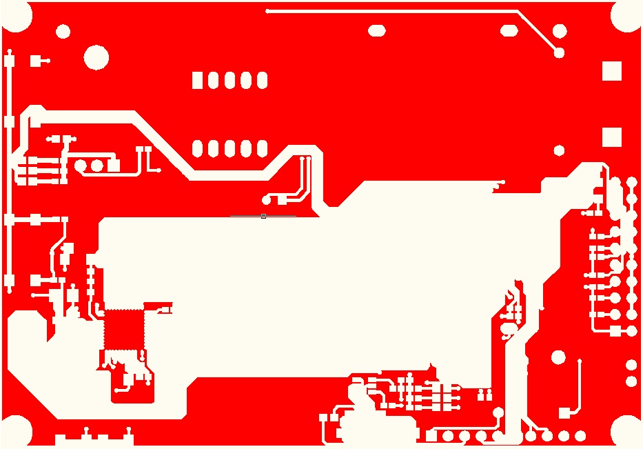
Fig. eight
Now you need to put the fill in the original contour. Make the selection of the fill, click Transfer from the Edit panel. Do not forget to include the binding - Fig. 9.

Fig. 9
Selecting the base point on the fill and the same base point on the contour on the board, the object snapping will allow you to make the transfer of the fill clearly to the same place where the contour is located - Figure 10.

The result of our actions in Figure 11. Similarly, create fills for all required layers.

Fig. eleven
Thank you for your attention, I hope this post will be useful to someone, as it would be useful to me some time ago. Sorry for any inaccuracies or omissions.
In my first post, I want to describe the process of exporting Altium Designer’s PCB objects like polygons. I encountered this problem more than once during the course and diploma projects at the university. They are required to draw up documentation on ESKD, and this means that the package of documentation must include a drawing "Printed circuit boards". An experienced user will note that the drawing can also be made in Altium itself by using mechanical layers for frames, duplicating layers and transferring them, and so on. But I prefer to use AutoCAD , as a more familiar environment for the design of drawings.
')
The essence of the problem and the solution below.
Altium has a whole range of exporters, among which is an exporter in .DXF. In releases it has been around for a long time and generally works well - footprints are exported in the form of blocks or primitives, vias and pads with holes on separate layers, support for different versions of AutoCAD, the possibility of layers one by one, stacks and so on. All this works remarkably well when exporting a board trace without polygon fill objects. When trying to export something similar to the one shown in fig. 1. In .DXF you get something shown in Fig. 2
Fig. one
Fig. 2
The exporter, instead of polygons, transfers only their outlines. 3
Fig. 3
How to restore polygons? Being just a novice designer and having interrupted the Internet for some time that was not acceptable for solving such a task, I decided to try to solve the problem on my own. And here is my action plan as follows.
Step 1. Export proper
We do everything as usual. Go to File> Save As ... In the Save as type field, select .dwg, .dxf from the drop-down list. Next, set the export options from the window in Fig. four.
Fig. four
Here we select Metric units, vias and pads with holes on different layers, we export the seats in blocks, and in the Layers field, select the Currently Visible Layers . Then only visible layers are exported. Since for the drawing of the board I do not need mechanical and other layers, I left only Top, Bottom and 2 inner layers visible. Altium 'e board and export results to AutoCAD ' e in Figures 1 and 2 at the beginning of the post.
Step 2. Selection of areas of polygons.
Create a fill and AutoCAD is not difficult, but for this you need to select all the lines that limit it. On the original board after the export, this is problematic. So you need to figure out how to select all the lines at once. Starting to look at the picture, I noticed that the tracks, holes and contact pads are transferred with the “Polyline” line type, while the outlines of the polygons (Fig. 3) are with the “Segments” type. That was enough to use filter selection. In AutoCAD on the Main tab, we find the Utilities section and click “Quick Pick” - icon with lightning, pic. five.
Fig. five
Set the selection parameters, as in Figure 6. In this case, select all segments on the TOP LAYER layer, if necessary on the other, select another one.
Fig. 6
The result will be the selection of all the lines that limit the polygon. Press Ctrl + C and paste this contour onto the free space in the drawing - the result is in fig. 7
Fig. 7
Step 3. Fill and transfer.
Now everything is simple - create a hatching ( AutoCAD main tab, Drawing panel). From the settings dialog, select the type of hatching Solid , or any other one. Click the button "Add: select objects". Select the entire contour and press Enter. In the setup dialog click OK. It turns out our landfill - Figure 8.
Fig. eight
Now you need to put the fill in the original contour. Make the selection of the fill, click Transfer from the Edit panel. Do not forget to include the binding - Fig. 9.
Fig. 9
Selecting the base point on the fill and the same base point on the contour on the board, the object snapping will allow you to make the transfer of the fill clearly to the same place where the contour is located - Figure 10.
The result of our actions in Figure 11. Similarly, create fills for all required layers.
Fig. eleven
Thank you for your attention, I hope this post will be useful to someone, as it would be useful to me some time ago. Sorry for any inaccuracies or omissions.
Source: https://habr.com/ru/post/162531/
All Articles