Programmable microcontroller STM32 - right off the bat
Below is described my first experience with a programmable microcontroller in the face of STM32VLDiscovery , the result of which was a machine from LEGO, controlled from the phone, and one more thing. I tried to state my way in the form of a step-by-step guide to action, but I warn you right away, not the “how to do it right” manual. The first two sections are a preface and do not relate directly to this microcontroller.
')
No matter why, but the thought arose: to make a device that receives commands from the phone. How to do it? It can be via Bluetooth, WiFi, USB, etc. But it seemed simpler and more versatile to me the recognition of sounds that can be taken from the output of a mobile phone headset (hereinafter, the simplest to implement, result-oriented methods will be chosen to solve problems).
Sounds can be synthesized by a special program for a smartphone, but there is an interesting option - DTMF signals. They are standard and are used in any mobile and in most fixed phones (when dialing a number or in the voice menu), they are transmitted without problems in the voice channel.
Three options for implementing DTMF decryption are printed from the Internet (my idea is not new), with them to a well-known store. It is bought:
We collect, check, correct errors ... it works. Shock.
Now all this needs to be made to control the machine. Moreover, the actions of the machine correspond logically to the pressed figure: 2 - forward, 4 - to the left, 6 - to the right, 8 - back.
The simplest option is the decimal descrambler. The K155ID10 with an open collector was bought - 4 inputs for a binary code, 10 outputs symbolize numbers from 0 to 9, on the required output there will be “0”, on the others - “1”. This decoder is used with loads whose operating current can reach 80 mA (incandescent bulbs, relays), which is convenient. Although transistors still had to be used.
All my childhood, I collected cars from LEGO, which went back and forth by manually switching the polarity of the batteries (I never had LEGO kits with motors and remotes). Now it's time to play toys in an adult way.
Normal people do H-bridge transistors. Advanced - buy a turnkey solution on these transistors. I did on switching electromagnetic relays. Later I bought powerful (for a collector current up to 3A) NPN and PNP transistors TIP31 C ST and TIP32 C ST, I assembled the same H-bridge from them, but for some reason it worked only with counter-lit LEDs, and the motor was not turning power I do not know why.
Switching relays require two for each motor (transistors or closing relays require 4). By default, both contacts of a motor (a common collector, as in toys) are connected to a minus. If one of the relays gives a control signal, the contact of the motor will switch to plus, the motor will work. The great advantage of such a connection is that under no circumstances can even a short-term short circuit be caused by the relay. The disadvantage is that when the control voltage is removed from the relay, the motor is short-circuited and becomes a brake. The solution is another closing relay. Now, to rotate the motor, it is also necessary to close it, too, for free running - to open it, for “braking” - to close it again. This relay will be added later.
There are two motors in a typewriter: one through the LEGO differential drives the rear wheels, the other turns the front wheels. The plastic gears in the gearboxes do not add efficiency to the system, but it all works.
We put on the board 4 relays. I was told that the breadboard was not designed for large currents (each motor consumes 1-1.6 A), but if I don’t get the result in a short time, the project risks remaining just another air lock. By the way, turning on any relay caused voltage surges, which led to looping and malfunctioning. Surely this is solved by special schemes, but I just powered the motors from a separate unit with batteries.
Electromagnetic relays, two power sources - is it a bit hardcore? Further more!
It remains to connect all this to a decimal decoder. The necessary outputs to the emitters of 4 NPN-transistors BC547, to the base of which the signal from the DTMF-decoder that the key is currently pressed (“fifth pin”), collectors - to each of the relays. Crooked, strange, but it works.


Suppose the machine should be able to go and turn at the same time. It is logical for this to use the numbers 1, 3, 7, 9, when clicked, which will trigger two relays. Initially, I planned to implement this by connecting diodes from the emitters of transistors to a decimal decoder, but this all did not work. Now it comes to me that if the decimal decoder produces “0”, then a PNP transistor is needed, which will open with this “zero”. But I only had NPN.
For the purposes of entertainment / mastering / use, logical elements 4-AND, 4-OR, NOT, AND-NOT, OR-NOT, AND one-by-one are purchased. The very first thought was to use the pins from the decimal decoder and the “fifth pin” from the DTMF decoder in a simple logic circuit, which ultimately will open the necessary transistors (and through them the relay). But! The decimal decoder K155ID10 as a “unit” gives 2 with something Volta. None of the available logic elements has considered such a signal as a “unit”. In addition to 4-I (KR1533). If using “bare” 4 bits of binary code with DTMF, then it was not possible to assemble the required logic from the available elements. A normal decimal decoder would make the task many times easier. And it turned out such a small mockery - to make it hard, but you can do the same! (The idea to go to bed and go for details in the morning was rejected).
Bearing in mind that the decimal descrambler gives out its “under-unit” to all conclusions, except for the output with the decrypted number, we do the following.
At first ... m ... quartet of the elements of element 4-I serve the numbers 1, 2, 3 and "one"; on the second - 7, 8, 9 and “one”. From the output of the first one we get “zero”, if it was pressed 1, 2 or 3 (the machine goes forward), from the output of the second one - if 7, 8, 9 (back). Otherwise, both outputs of the 4-I element are “units”.
Now turns. We use the 5 remaining logical elements and collect a cunning scheme. It was decided to give up numbers 4 and 6 (why turn the wheels on the spot ?!), but even drawing up a scheme for turns with only 1 and 7 (to the left), 3 and 9 (to the right) made us pretty tense.
As a result, on the board (I had to buy one more, more) DTMF-decoder, an indicator, a decoder for it, a decimal decoder, 4-AND, NOT, 4-OR, OR-NOT, AND-NO, 4 transistors, 4 relays.
The machine performs 6 different commands, but does not know how to return the front wheels to the middle. The efficiency of LEGO parts and the low power of the motor do not allow making a return spring or a rubber band.
Relays sometimes clink several times, the reasons are not clear (interference?).
The logic of working with logic mastered.

Development environment
It is time to move from programming to code to programming. About programmable microcontrollers / chips, I had only vague ideas that the Raspberry Pi is too powerful, the Arduino is expensive and not comme il faut. It was then that the seller Michael and wrote me STM32VLDiscovery for 579 rubles. About him here and not only here have already written, which greatly helped me in his study.
The controller can be plugged into the breadboard, but not into any. At the same time, 6 legs will remain hanging - you can do without them, the benefit remains a few dozen. You can check the functionality of the program flooded into memory without even disconnecting the board from the mini-USB cable through which the program entered the device. And you can eat from him.
The best choice to get started was the CoIDE environment from CooCox, which required just one dance with tambourines — manually downloading certain files to a specific folder. True, I didn’t manage to upload firmware from it to the device - I have to use ST-LINK Utility from the board manufacturer. They say that you can compile directly from convenient Sublime Text 2, but the length of the instruction has put too much skepticism into me to try.
Considering that I never wrote to C, even the simplest flashes of LEDs caused me considerable difficulties. In addition, incomprehensible registers, a hexadecimal system, different modes of operation of the outputs and inputs for a person who does not understand the purpose of the pull-up resistor ... But the copy-paste method of someone's ready-made examples did his job. In turn, the price of the device allows you not to bother too much with the correct connection of the hardware. For example, I did not understand whether it is necessary to connect each GND leg to the ground and whether it is harmful to power the device from 4-finger batteries - as long as everything is alive and working.
Closer to the code. I will not give and describe other examples here, but I offer you some of my best practices. They appeared at a time when there was no acceptable solution to a particular problem on the Web.
For example, we want to turn on the LED, and after a while to turn it off. Often, the delay is implemented by an empty loop that runs many times. The method is certainly simple, but it is applicable only where nothing except the flashing of the LED from the board is required. We can interrupt the cycle only, excuse me, by interrupting (about them a bit later) or set additional conditions for exiting the cycle. Otherwise, the board does nothing and does not react to anything while this cycle lasts.
What I propose is: we use our main infinite loop for all the delays in the program at once, increasing each pass by the value of a certain variable (let's call it “x”). As soon as a variable reaches certain values, certain conditions are triggered in the body of the loop (there may be as many of them). The disadvantage is that we do not know in advance how long such a delay will last. If it does not matter, we select empirically necessary values and use them.
Suppose we did not change the crystal resonator, and the processor frequency remained 24 MHz. By creating an interrupt when the processor reaches the 2400th countdown through special instructions, we will get the execution of the function TIM6_DAC_IRQHandler (this is an interrupt handler) with a frequency of 100 Hz - every 10 milliseconds. The code below was originally taken somewhere.
The main purpose of this interrupt is to use the variable ti, which increases exactly every 10 milliseconds. Soon I found out that interrupts are not just “wedged” into the main program code, but can also distort the comparison operation or assignment to the variable ti, since it changes in the interrupt handler every time. A situation may arise when instead of assigning another variable the value of the variable ti, a part of the old value and a part of the new value will be assigned. Among the solutions to the problem found on the Web, I singled out about the following:
I solved this problem like this. We assign a variable ti to a local variable sti until it is "assigned". You can add a little “backlash” if accuracy is not fundamental.
By itself, the local variable sti is used only to not insert such cycles wherever we need the value of the variable ti.
Further in the program, you can fearlessly access the sti variable and even reset it. I used all this to fix the time during which this or that team was given a typewriter so that the machine could then repeat the route. Naturally, zeroing should not be in vain, so at the end of the main program loop, some simple code was added:
If at the moment of assignment or at the moment of checking the exit condition the variable ti changes and is “presented” in an incorrect form, the cycle will repeat. The higher the interrupt frequency, the more often the exit condition from the cycle will work the second time. Naturally, if the interrupt frequency is too high, looping will not keep you waiting. To control the number of failed assignment attempts, I used LEDs.
Sometimes, to adjust the program, you want to get the values of certain variables during the operation of the device, but there is no display or indicator at hand or you do not want to connect them. Then you can simply make the LEDs blink the required number of times, pause, blink again, etc. For these purposes, I use the following code in the body of the main loop:
At any place in the program, we assign the variable todisp, for example, 3, and the LED No. 8 on the board will flash three times, making a second pause between series. The sti variable is incremented every 10 milliseconds (via the variable ti), instead you can use the variable x, incremented with each pass of the main loop. In this case, the coefficients will need to be slightly increased.
In this example, each time, because of an interruption, the assignment operation sti = ti was incorrect and, therefore, the comparison operation ti> 1 + sti returns true (which can also occur if the interruption happened at the time of comparison), the LED will flash for one times more. In principle, you can even measure how many times the LED flashes after n minutes of the board’s operation and calculate the average cycle time (based on the interrupt frequency), and also make sure that all these precautions when using interrupts are not superfluous.
After conducting a sufficient number of experiments on LEDs, you can gradually change them to the wheels. We take from the old circuit on the basic logic only the most necessary: DTMF-decoder, an indicator with a decoder for beauty, a relay with transistors. You can finally forget about the decimal decoder!
The outputs from the DTMF decoder are connected to the inputs on the controller that we have chosen for this purpose. The outputs from the controller (again, selected and initialized in the program) via a resistor (for example, 3 kΩ) to the base of a normal NPN transistor (I used the BC547). Emitters - to "plus", collectors - to the coil of the corresponding relay. Add the fifth relay, which prevents shorting (“brake” mode) of the main motor, turn signals / dimensions to taste. "Plus" for motors is supplied to the relay from a separate battery pack. To power both the circuit and the motors, I use plastic cases (2 pieces) for 4 finger-type batteries / accumulators each. They cost only 40 rubles, and I always suffered in childhood with scotch and foil ...
It turned out that the wires from the DTMF decoder pass exactly above the relay, which are responsible for moving forward / backward. Perhaps this adds interference to the existing power surges when the relay is turned on. As a result, during the presentation before the fellow students the relays began to periodically pop, and the machine refused to go back at all - the relay switched non-stop, issuing a uniform crash. Diodes connected in parallel to the coils of the relay in the direction of "plus", did not affect this situation. We are finalizing the program - every 10 milliseconds we check the values of the inputs and react to changes only if the combination of five inputs is the same 6 times in a row. Delay on the eye is almost imperceptible, the problem with interference is solved. Here they are, the main advantages of programmable microcontrollers!
In the second part, I mentioned that it’s impossible to mechanically align the front wheels in the middle. It's time to solve the problem, because the machine should be able to drive in a straight line!
The decision suggests itself - if not the spring, then let the motor itself spin in the opposite direction until it aligns the wheels. Digital encoders are not at hand, but there is a remarkable 10 kΩ rheostat, the board has a 12-bit ADC (even 2), the Internet has a connection scheme and code. The ends of the rheostat to the "plus" and "minus", the slider through a 1 kΩ resistor to the input. By the way, for the purposes of the ADC, you can not use any input. I used the one that was specified in the example. Sample code can be found directly in CoIDE for each of the libraries, including the ADC (do not forget to connect the ADC library to CoIDE). The code is copy-paste in my program and, most importantly, it works.
Now we install the rheostat in the machine, we connect the rheostat shaft coaxially with the output shaft of the “gearbox” of the turning mechanism - it is the third from the motor. The process of conjugation of non-LEGO parts with LEGO's always delivers, but the motor still manages to turn the rheostat and turn the wheels. With difficulty, I must say. Three wires stretch from the resistor to the board, four more are pulled from the motors.
The empirical method selects numerical values from 0 to 4095, corresponding to acceptable left and right boundaries of the angle of rotation of the front wheels when they are installed straight. It seems that this range is called the dead zone - within its wheels are considered aligned to the middle. I also picked up the values for turning off the motor when the maximum angle of rotation was reached.
If the machine is operated in extreme modes, and under the influence of monstrous overloads, the wheels suddenly change the angle of rotation without the appropriate command, the same code will return them to the desired position. If we press, for example, 4, and the wheels are already in the extreme left position, the relay will not turn on.
Let me remind you that some code was taken from someone else's examples.


It works like this:
Since the ADC was mastered, then the DAC should not be ignored. The most obvious way to use it for educational and entertainment purposes seems to me the generation of sounds. The order of mastering is classic: we find a ready-made example on the Web, we run, “wow!”, We modify the code.
I connected the loudspeaker to the plus and to the collector of the NPN transistor, the signal from the foot to which the DAC is connected comes to the base of the transistor through a resistor. In theory, the speaker is powered by an electrical audio signal with varying polarity, but I apply current to the speaker in only one direction. I tried different circuits about two transistors, but I could not hear a significant difference in sound. Maybe I just did not find a suitable scheme.
The first sounds were obtained using this example.
It would be nice to calculate what frequency the squeaking should turn out, based on the program code, and compare the result with the tuner readings. Processor frequency: 24,000,000 Hz. The TIM6-> PSC timer is reset when it reaches zero, i.e. every beat. Timer TIM6-> ARR counts up to 500, i.e. The interrupt is triggered at every 501th reset of TIM6-> PSC - in our case it is (24,000,000 Hz / 1) / 501 ≈ 47 904 Hz. This is the sampling frequency of the future sound signal. , - mp3 44 100 . , , — 16 12. , .
— , 32 sin. : 47 904 / 32 ≈ 1 497 . ( 5 ), … «!». F#6, , : 1 497,1 .

Since , - . -, . , 5 , 10 . :
TIM6->PSC = 23; // 1 M
TIM6->ARR = 99; // PSC 23 ARR 99 100 (10 )
, , — 27,5 . , (440 , ), 11 ( ). ( 12 n ).
: , Excel . , . . , (), . 2 400 . Excel, , :
. Result:
, ( 1, 2, 4, 8 ..):
i 100 :
, . , Nokia:
, ?..
(), , :
( ). But! 0 4095, . , , . 100 …
.
, - ? Yes.
, , STM32VLDiscovery, . :
1. Youtube Aston Martin.
2. ( ) .
3. ( Audacity ).
4. . 24 . , 2 , 2-3 -. Just right.
5. WAV-.
6. ( WAV 2 TEXT) — -, . , .
7. 0 4095 Excel. 60 000 Notepad++ Sublime Text, . Excel 30 , — CoIDE …
8. .
, over 9000 . :
, , , , , :
Something like this.
Content:
- The first contact with microelectronics.
- Construction of cars on non-programmable logic elements.
- Getting started with STM32. Development environment. Connect the microcontroller to the typewriter.
- Determine the angle of rotation of the front wheels - feedback through the ADC.
- Use a DAC to play sounds.
')
1. First contact with microelectronics
No matter why, but the thought arose: to make a device that receives commands from the phone. How to do it? It can be via Bluetooth, WiFi, USB, etc. But it seemed simpler and more versatile to me the recognition of sounds that can be taken from the output of a mobile phone headset (hereinafter, the simplest to implement, result-oriented methods will be chosen to solve problems).
Sounds can be synthesized by a special program for a smartphone, but there is an interesting option - DTMF signals. They are standard and are used in any mobile and in most fixed phones (when dialing a number or in the voice menu), they are transmitted without problems in the voice channel.
Task 1: Recognize DTMF Signals
Three options for implementing DTMF decryption are printed from the Internet (my idea is not new), with them to a well-known store. It is bought:
- MT 8870DE Decoder - from the input analog signal receives a binary code (4 bits) of the last recognized DTMF command and 1 bit - the presence / absence of the DTMF command this very second (let's call it “fifth output”).
- Quartz resonator, capacitors and resistors necessary for the operation of the decoder.
- 7-segment indicator - to display the number pressed on the phone.
- KP 514ID-1 decoder for a 7-segment indicator - from the binary code receives 7 outputs for each of the segments.
- Breadboard for installation without soldering.
- Wiring / jumper for the breadboard.
We collect, check, correct errors ... it works. Shock.
Now all this needs to be made to control the machine. Moreover, the actions of the machine correspond logically to the pressed figure: 2 - forward, 4 - to the left, 6 - to the right, 8 - back.
Task 2: 4 certain combinations of signals from a DTMF decoder must activate one of the 4 functions
The simplest option is the decimal descrambler. The K155ID10 with an open collector was bought - 4 inputs for a binary code, 10 outputs symbolize numbers from 0 to 9, on the required output there will be “0”, on the others - “1”. This decoder is used with loads whose operating current can reach 80 mA (incandescent bulbs, relays), which is convenient. Although transistors still had to be used.
Task 3: Change polarity for motors, N-bridge
All my childhood, I collected cars from LEGO, which went back and forth by manually switching the polarity of the batteries (I never had LEGO kits with motors and remotes). Now it's time to play toys in an adult way.
Normal people do H-bridge transistors. Advanced - buy a turnkey solution on these transistors. I did on switching electromagnetic relays. Later I bought powerful (for a collector current up to 3A) NPN and PNP transistors TIP31 C ST and TIP32 C ST, I assembled the same H-bridge from them, but for some reason it worked only with counter-lit LEDs, and the motor was not turning power I do not know why.
Switching relays require two for each motor (transistors or closing relays require 4). By default, both contacts of a motor (a common collector, as in toys) are connected to a minus. If one of the relays gives a control signal, the contact of the motor will switch to plus, the motor will work. The great advantage of such a connection is that under no circumstances can even a short-term short circuit be caused by the relay. The disadvantage is that when the control voltage is removed from the relay, the motor is short-circuited and becomes a brake. The solution is another closing relay. Now, to rotate the motor, it is also necessary to close it, too, for free running - to open it, for “braking” - to close it again. This relay will be added later.
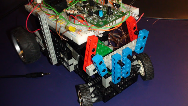
Task 4: Assemble the machine
There are two motors in a typewriter: one through the LEGO differential drives the rear wheels, the other turns the front wheels. The plastic gears in the gearboxes do not add efficiency to the system, but it all works.
We put on the board 4 relays. I was told that the breadboard was not designed for large currents (each motor consumes 1-1.6 A), but if I don’t get the result in a short time, the project risks remaining just another air lock. By the way, turning on any relay caused voltage surges, which led to looping and malfunctioning. Surely this is solved by special schemes, but I just powered the motors from a separate unit with batteries.
Electromagnetic relays, two power sources - is it a bit hardcore? Further more!
It remains to connect all this to a decimal decoder. The necessary outputs to the emitters of 4 NPN-transistors BC547, to the base of which the signal from the DTMF-decoder that the key is currently pressed (“fifth pin”), collectors - to each of the relays. Crooked, strange, but it works.
2. Construction of cars on non-programmable logic elements
Suppose the machine should be able to go and turn at the same time. It is logical for this to use the numbers 1, 3, 7, 9, when clicked, which will trigger two relays. Initially, I planned to implement this by connecting diodes from the emitters of transistors to a decimal decoder, but this all did not work. Now it comes to me that if the decimal decoder produces “0”, then a PNP transistor is needed, which will open with this “zero”. But I only had NPN.
Task 5: The machine should go and turn when you press 1, 3, 7 or 9
For the purposes of entertainment / mastering / use, logical elements 4-AND, 4-OR, NOT, AND-NOT, OR-NOT, AND one-by-one are purchased. The very first thought was to use the pins from the decimal decoder and the “fifth pin” from the DTMF decoder in a simple logic circuit, which ultimately will open the necessary transistors (and through them the relay). But! The decimal decoder K155ID10 as a “unit” gives 2 with something Volta. None of the available logic elements has considered such a signal as a “unit”. In addition to 4-I (KR1533). If using “bare” 4 bits of binary code with DTMF, then it was not possible to assemble the required logic from the available elements. A normal decimal decoder would make the task many times easier. And it turned out such a small mockery - to make it hard, but you can do the same! (The idea to go to bed and go for details in the morning was rejected).
Bearing in mind that the decimal descrambler gives out its “under-unit” to all conclusions, except for the output with the decrypted number, we do the following.
At first ... m ... quartet of the elements of element 4-I serve the numbers 1, 2, 3 and "one"; on the second - 7, 8, 9 and “one”. From the output of the first one we get “zero”, if it was pressed 1, 2 or 3 (the machine goes forward), from the output of the second one - if 7, 8, 9 (back). Otherwise, both outputs of the 4-I element are “units”.
Now turns. We use the 5 remaining logical elements and collect a cunning scheme. It was decided to give up numbers 4 and 6 (why turn the wheels on the spot ?!), but even drawing up a scheme for turns with only 1 and 7 (to the left), 3 and 9 (to the right) made us pretty tense.
As a result, on the board (I had to buy one more, more) DTMF-decoder, an indicator, a decoder for it, a decimal decoder, 4-AND, NOT, 4-OR, OR-NOT, AND-NO, 4 transistors, 4 relays.
The machine performs 6 different commands, but does not know how to return the front wheels to the middle. The efficiency of LEGO parts and the low power of the motor do not allow making a return spring or a rubber band.
Relays sometimes clink several times, the reasons are not clear (interference?).
The logic of working with logic mastered.
3. Getting Started with STM32
Development environment
It is time to move from programming to code to programming. About programmable microcontrollers / chips, I had only vague ideas that the Raspberry Pi is too powerful, the Arduino is expensive and not comme il faut. It was then that the seller Michael and wrote me STM32VLDiscovery for 579 rubles. About him here and not only here have already written, which greatly helped me in his study.
The controller can be plugged into the breadboard, but not into any. At the same time, 6 legs will remain hanging - you can do without them, the benefit remains a few dozen. You can check the functionality of the program flooded into memory without even disconnecting the board from the mini-USB cable through which the program entered the device. And you can eat from him.
The best choice to get started was the CoIDE environment from CooCox, which required just one dance with tambourines — manually downloading certain files to a specific folder. True, I didn’t manage to upload firmware from it to the device - I have to use ST-LINK Utility from the board manufacturer. They say that you can compile directly from convenient Sublime Text 2, but the length of the instruction has put too much skepticism into me to try.
Considering that I never wrote to C, even the simplest flashes of LEDs caused me considerable difficulties. In addition, incomprehensible registers, a hexadecimal system, different modes of operation of the outputs and inputs for a person who does not understand the purpose of the pull-up resistor ... But the copy-paste method of someone's ready-made examples did his job. In turn, the price of the device allows you not to bother too much with the correct connection of the hardware. For example, I did not understand whether it is necessary to connect each GND leg to the ground and whether it is harmful to power the device from 4-finger batteries - as long as everything is alive and working.
Closer to the code. I will not give and describe other examples here, but I offer you some of my best practices. They appeared at a time when there was no acceptable solution to a particular problem on the Web.
Task 6: Delay
For example, we want to turn on the LED, and after a while to turn it off. Often, the delay is implemented by an empty loop that runs many times. The method is certainly simple, but it is applicable only where nothing except the flashing of the LED from the board is required. We can interrupt the cycle only, excuse me, by interrupting (about them a bit later) or set additional conditions for exiting the cycle. Otherwise, the board does nothing and does not react to anything while this cycle lasts.
What I propose is: we use our main infinite loop for all the delays in the program at once, increasing each pass by the value of a certain variable (let's call it “x”). As soon as a variable reaches certain values, certain conditions are triggered in the body of the loop (there may be as many of them). The disadvantage is that we do not know in advance how long such a delay will last. If it does not matter, we select empirically necessary values and use them.
Code
int main(void) { unsigned int x=0; char something; while(1) { if (x>5000) { // }; if (x==10000) { // . , x. }; if (something==1)// { x=0; // } if (x<15000) { x++; }; // x 0, x 15000. }; }; Task 7: Interrupts at a specified interval
Suppose we did not change the crystal resonator, and the processor frequency remained 24 MHz. By creating an interrupt when the processor reaches the 2400th countdown through special instructions, we will get the execution of the function TIM6_DAC_IRQHandler (this is an interrupt handler) with a frequency of 100 Hz - every 10 milliseconds. The code below was originally taken somewhere.
Code
unsigned int ti=0; int main(void) { // 6 RCC_APB1PeriphClockCmd(RCC_APB1Periph_TIM6,ENABLE); TIM6->PSC = 24000 - 1; // 1000 TIM6->ARR = 10 - 1; // 10- TIM6->DIER |= TIM_DIER_UIE; // TIM6->CR1 |= TIM_CR1_CEN; // ! NVIC_EnableIRQ(TIM6_DAC_IRQn); // TIM6_DAC_IRQn }; // TIM6_DAC void TIM6_DAC_IRQHandler(void) { ti++; TIM6->SR &= ~TIM_SR_UIF; // } The main purpose of this interrupt is to use the variable ti, which increases exactly every 10 milliseconds. Soon I found out that interrupts are not just “wedged” into the main program code, but can also distort the comparison operation or assignment to the variable ti, since it changes in the interrupt handler every time. A situation may arise when instead of assigning another variable the value of the variable ti, a part of the old value and a part of the new value will be assigned. Among the solutions to the problem found on the Web, I singled out about the following:
- the use of atomic operations (they are not interrupted) - the assignment of the int type is not such, and it is necessary to use the “long” type;
- using additional variables or registers to find out if the interruption worked during the execution of specific instructions was a bit cumbersome and not very clear (for me);
- other options...
I solved this problem like this. We assign a variable ti to a local variable sti until it is "assigned". You can add a little “backlash” if accuracy is not fundamental.
do { sti=ti; } while (ti>1+sti); By itself, the local variable sti is used only to not insert such cycles wherever we need the value of the variable ti.
Further in the program, you can fearlessly access the sti variable and even reset it. I used all this to fix the time during which this or that team was given a typewriter so that the machine could then repeat the route. Naturally, zeroing should not be in vain, so at the end of the main program loop, some simple code was added:
if (sti==0) { do { ti=0; } while (ti>1); } If at the moment of assignment or at the moment of checking the exit condition the variable ti changes and is “presented” in an incorrect form, the cycle will repeat. The higher the interrupt frequency, the more often the exit condition from the cycle will work the second time. Naturally, if the interrupt frequency is too high, looping will not keep you waiting. To control the number of failed assignment attempts, I used LEDs.
Task 8: LEDs as a display
Sometimes, to adjust the program, you want to get the values of certain variables during the operation of the device, but there is no display or indicator at hand or you do not want to connect them. Then you can simply make the LEDs blink the required number of times, pause, blink again, etc. For these purposes, I use the following code in the body of the main loop:
// - if ((todisp>0) && (sti%10==0)) { if ((sti%(todisp*20+100)<todisp*20) && (sti%20<10)) { GPIOC->BSRR=GPIO_BSRR_BS8; } else { GPIOC->BRR=GPIO_BRR_BR8; }; }; At any place in the program, we assign the variable todisp, for example, 3, and the LED No. 8 on the board will flash three times, making a second pause between series. The sti variable is incremented every 10 milliseconds (via the variable ti), instead you can use the variable x, incremented with each pass of the main loop. In this case, the coefficients will need to be slightly increased.
Usage example
while (1) { do { sti=ti; todisp++; } while (ti>1+sti); todisp--; if ((todisp>0) && (sti%10==0)) { if ((sti%(todisp*20+100)<todisp*20) && (sti%20<10)) { GPIOC->BSRR=GPIO_BSRR_BS8; } else { GPIOC->BRR=GPIO_BRR_BR8; }; }; } In this example, each time, because of an interruption, the assignment operation sti = ti was incorrect and, therefore, the comparison operation ti> 1 + sti returns true (which can also occur if the interruption happened at the time of comparison), the LED will flash for one times more. In principle, you can even measure how many times the LED flashes after n minutes of the board’s operation and calculate the average cycle time (based on the interrupt frequency), and also make sure that all these precautions when using interrupts are not superfluous.
Task 9: Connect the microcontroller to the typewriter
After conducting a sufficient number of experiments on LEDs, you can gradually change them to the wheels. We take from the old circuit on the basic logic only the most necessary: DTMF-decoder, an indicator with a decoder for beauty, a relay with transistors. You can finally forget about the decimal decoder!
The outputs from the DTMF decoder are connected to the inputs on the controller that we have chosen for this purpose. The outputs from the controller (again, selected and initialized in the program) via a resistor (for example, 3 kΩ) to the base of a normal NPN transistor (I used the BC547). Emitters - to "plus", collectors - to the coil of the corresponding relay. Add the fifth relay, which prevents shorting (“brake” mode) of the main motor, turn signals / dimensions to taste. "Plus" for motors is supplied to the relay from a separate battery pack. To power both the circuit and the motors, I use plastic cases (2 pieces) for 4 finger-type batteries / accumulators each. They cost only 40 rubles, and I always suffered in childhood with scotch and foil ...
It turned out that the wires from the DTMF decoder pass exactly above the relay, which are responsible for moving forward / backward. Perhaps this adds interference to the existing power surges when the relay is turned on. As a result, during the presentation before the fellow students the relays began to periodically pop, and the machine refused to go back at all - the relay switched non-stop, issuing a uniform crash. Diodes connected in parallel to the coils of the relay in the direction of "plus", did not affect this situation. We are finalizing the program - every 10 milliseconds we check the values of the inputs and react to changes only if the combination of five inputs is the same 6 times in a row. Delay on the eye is almost imperceptible, the problem with interference is solved. Here they are, the main advantages of programmable microcontrollers!
4. Determine the angle of rotation of the front wheels - feedback through the ADC (analog-digital converter)
In the second part, I mentioned that it’s impossible to mechanically align the front wheels in the middle. It's time to solve the problem, because the machine should be able to drive in a straight line!
Task 10: Connecting the rheostat
The decision suggests itself - if not the spring, then let the motor itself spin in the opposite direction until it aligns the wheels. Digital encoders are not at hand, but there is a remarkable 10 kΩ rheostat, the board has a 12-bit ADC (even 2), the Internet has a connection scheme and code. The ends of the rheostat to the "plus" and "minus", the slider through a 1 kΩ resistor to the input. By the way, for the purposes of the ADC, you can not use any input. I used the one that was specified in the example. Sample code can be found directly in CoIDE for each of the libraries, including the ADC (do not forget to connect the ADC library to CoIDE). The code is copy-paste in my program and, most importantly, it works.
Now we install the rheostat in the machine, we connect the rheostat shaft coaxially with the output shaft of the “gearbox” of the turning mechanism - it is the third from the motor. The process of conjugation of non-LEGO parts with LEGO's always delivers, but the motor still manages to turn the rheostat and turn the wheels. With difficulty, I must say. Three wires stretch from the resistor to the board, four more are pulled from the motors.
Task 11: Using data from a rheostat
The empirical method selects numerical values from 0 to 4095, corresponding to acceptable left and right boundaries of the angle of rotation of the front wheels when they are installed straight. It seems that this range is called the dead zone - within its wheels are considered aligned to the middle. I also picked up the values for turning off the motor when the maximum angle of rotation was reached.
Code
js= 2500; // j — 0 4095 () gist=150; // full=500; // while (1) { //... if ((x>=max*7) && (inpok)) // inpok 0, . . if ((num==1) || (num==4) || (num==7)) // { GPIOC->BRR=GPIO_BRR_BR7; if (j>0+full) { GPIOC->BSRR=GPIO_BSRR_BS6; } else { if (j<0+full-gist) { GPIOC->BRR=GPIO_BRR_BR6; } } } else { GPIOC->BRR=GPIO_BRR_BR1; } if ((num==3) || (num==6) || (num==9)) // { GPIOC->BRR=GPIO_BRR_BR6; if (j<4250-full) { GPIOC->BSRR=GPIO_BSRR_BS7; // « » } else { if (j>4250-full+gist) { GPIOC->BRR=GPIO_BRR_BR7; // « » } } } else { GPIOC->BRR=GPIO_BRR_BR3; } // if ((num==2) || (num==5) || (num==8)) { if (j<js-gist*3) // { GPIOC->BRR=GPIO_BRR_BR6; // « » ( ) GPIOC->BSRR=GPIO_BSRR_BS7; // « » } else { if (j>js-gist*2) { GPIOC->BRR=GPIO_BRR_BR7; « » } }; if (j>js+gist*3) { GPIOC->BRR=GPIO_BRR_BR7; GPIOC->BSRR=GPIO_BSRR_BS6; } else { if (j<js+gist*2) { GPIOC->BRR=GPIO_BRR_BR6; } }; }; }; //.. } If the machine is operated in extreme modes, and under the influence of monstrous overloads, the wheels suddenly change the angle of rotation without the appropriate command, the same code will return them to the desired position. If we press, for example, 4, and the wheels are already in the extreme left position, the relay will not turn on.
Let me remind you that some code was taken from someone else's examples.
The final code of the machine control program
/** ***************************************************************************** * @title ADC_simple.c * @author Claude * @date 2010 Dec 29 * @brief ADC Example, Blink a LED according to ADC value ******************************************************************************* */ #include<stm32f10x_rcc.h> #include<stm32f10x_gpio.h> #include<stm32f10x_adc.h> #include "stm32f10x.h" #include "stm32f10x_conf.h" GPIO_InitTypeDef GPIO_InitStructure; ADC_InitTypeDef ADC_InitStructure; unsigned int i,j,js,gist,full,ti=0; /* Blink a LED, blink speed is set by ADC value */ int main(void) { unsigned int x,max; unsigned int move[10]; unsigned int oldsti=0,sti=0,time[10],tit=0; unsigned short recheck=5; unsigned char todisp=0,todisp2=0; x=0; unsigned char ji,ju,inp0,inp1,inp2,inp3,inpok,ink,in0,in1,in2,in3,inok,num,oldnum,back; max=250; inp0=0; inp1=0; inp2=0; inp3=0; inpok=0; ink=0; back=0; num=0; void backreset(void) { back=0; for (ju=0;ju<10;ju++) { time[ju]=0; move[ju]=0; } GPIOC->BRR=GPIO_BRR_BR9; } GPIO_InitTypeDef PORT,GPIO_InitStructure; RCC_APB2PeriphClockCmd(RCC_APB2Periph_GPIOC, ENABLE); PORT.GPIO_Pin = (GPIO_Pin_1 | GPIO_Pin_2 | GPIO_Pin_3 | GPIO_Pin_6 | GPIO_Pin_7 | GPIO_Pin_10 | GPIO_Pin_11 | GPIO_Pin_12| GPIO_Pin_8 | GPIO_Pin_9); PORT.GPIO_Mode = GPIO_Mode_Out_PP; PORT.GPIO_Speed = GPIO_Speed_2MHz; GPIO_Init( GPIOC , &PORT); RCC_APB2PeriphClockCmd(RCC_APB2Periph_GPIOB, ENABLE); // A GPIO_InitStructure.GPIO_Pin = (GPIO_Pin_9 | GPIO_Pin_4 | GPIO_Pin_5 | GPIO_Pin_6 | GPIO_Pin_7); // GPIO_InitStructure.GPIO_Mode = GPIO_Mode_IPU; GPIO_Init(GPIOB, &GPIO_InitStructure); RCC_APB2PeriphClockCmd(RCC_APB2Periph_GPIOA , ENABLE); PORT.GPIO_Pin = (GPIO_Pin_0 | GPIO_Pin_1 | GPIO_Pin_2 | GPIO_Pin_3 | GPIO_Pin_5); PORT.GPIO_Mode = GPIO_Mode_Out_PP; PORT.GPIO_Speed = GPIO_Speed_2MHz; GPIO_Init( GPIOA , &PORT); // input of ADC (it doesn't seem to be needed, as default GPIO state is floating input) GPIO_InitStructure.GPIO_Mode = GPIO_Mode_AIN; GPIO_InitStructure.GPIO_Pin = GPIO_Pin_1 ; // that's ADC1 (PA1 on STM32) GPIO_Init(GPIOA, &GPIO_InitStructure); //clock for ADC (max 14MHz --> 72/6=12MHz) RCC_ADCCLKConfig (RCC_PCLK2_Div6); // enable ADC system clock RCC_APB2PeriphClockCmd(RCC_APB2Periph_ADC1, ENABLE); // define ADC config ADC_InitStructure.ADC_Mode = ADC_Mode_Independent; ADC_InitStructure.ADC_ScanConvMode = DISABLE; ADC_InitStructure.ADC_ContinuousConvMode = ENABLE; // we work in continuous sampling mode ADC_InitStructure.ADC_ExternalTrigConv = ADC_ExternalTrigConv_None; ADC_InitStructure.ADC_DataAlign = ADC_DataAlign_Right; ADC_InitStructure.ADC_NbrOfChannel = 1; ADC_RegularChannelConfig(ADC1,ADC_Channel_1, 1,ADC_SampleTime_28Cycles5); // define regular conversion config ADC_Init ( ADC1, &ADC_InitStructure); //set config of ADC1 // enable ADC ADC_Cmd (ADC1,ENABLE); //enable ADC1 // ADC calibration (optional, but recommended at power on) ADC_ResetCalibration(ADC1); // Reset previous calibration while(ADC_GetResetCalibrationStatus(ADC1)); ADC_StartCalibration(ADC1); // Start new calibration (ADC must be off at that time) while(ADC_GetCalibrationStatus(ADC1)); // start conversion ADC_Cmd (ADC1,ENABLE); //enable ADC1 ADC_SoftwareStartConvCmd(ADC1, ENABLE); // start conversion (will be endless as we are in continuous mode) // debug information RCC_ClocksTypeDef forTestOnly; RCC_GetClocksFreq(&forTestOnly); //this could be used with debug to check to real speed of ADC clock // 6 RCC_APB1PeriphClockCmd(RCC_APB1Periph_TIM6,ENABLE); TIM6->PSC = 24000 - 1; // 1000 // TIM6->ARR = 1000 ; // TIM6->ARR =4; TIM6->DIER |= TIM_DIER_UIE; // TIM6->CR1 |= TIM_CR1_CEN; // ! NVIC_EnableIRQ(TIM6_DAC_IRQn); // TIM6_DAC_IRQn j= 2500; js=j; gist=150; full=500; if (back==0) { for (ju=0;ju<10;ju++) { time[ju]=0; move[ju]=0; } } while (1) { // adc is in free run, and we get the value asynchronously, this is not a really nice way of doing, but it work! j = ADC_GetConversionValue(ADC1) ; // value from 0 to 4095 /* possible change : * ADC_ContinuousConvMode = DISABLE * then on the infinite loop, something like : * * ADC_SoftwareStartConvCmd(ADC1, ENABLE); // start ONE conversion * while(ADC_GetFlagStatus(ADC1, ADC_FLAG_EOC) == RESET); // wait end of conversion * j = ADC_GetConversionValue(ADC1) * 500; // get value * */ do { sti=ti; } while (ti>1+sti); //if ((back!=2) || GPIO_ReadInputDataBit(GPIOB,GPIO_Pin_9)) if (oldsti!=sti) { oldsti=sti; if (ink<recheck) { in0+=GPIO_ReadInputDataBit(GPIOB,GPIO_Pin_5); in1+=GPIO_ReadInputDataBit(GPIOB,GPIO_Pin_6); in2+=GPIO_ReadInputDataBit(GPIOB,GPIO_Pin_7); in3+=GPIO_ReadInputDataBit(GPIOB,GPIO_Pin_8); inok+=GPIO_ReadInputDataBit(GPIOB,GPIO_Pin_9); ink++; if (ink==recheck) { ink=0; if ((in0==0 || in0==recheck) && (in1==0 || in1==recheck) && (in2==0 || in2==recheck) && (in3==0 || in3==recheck) && (inok==0 || inok==recheck)) { if (in0==recheck) { in0=1; } if (in1==recheck) { in1=1; } if (in2==recheck) { in2=1; } if (in3==recheck) { in3=1; } if (inok==recheck) { inok=1; } if ((back==2) && (inok==1)) { backreset(); } if ( (back!=2) && (back!=4) && ((inp0!=in0) || (inp1!=in1) || (inp2!=in2) || (inp3!=in3) || (inpok!=inok)) ) { x=0; inp0=in0; inp1=in1; inp2=in2; inp3=in3; inpok=inok; oldnum=num; if (inp0) // - { if (inp1) { if (inp2) { if (inp3) { num=15; } else { num=7; }; } else { if (inp3) { num=11; } else { num=3; }; }; } else { if (inp2) { if (inp3) { num=13; } else { num=5; }; } else { if (inp3) { num=9; } else { num=1; }; }; }; } else { if (inp1) { if (inp2) { if (inp3) { num=14; } else { num=6; }; } else { if (inp3) { num=10; } else { num=2; }; }; } else { if (inp2) { if (inp3) { num=12; } else { num=4; }; } else { if (inp3) { num=8; } else { num=0; }; }; }; }; }; } in0=0; in1=0; in2=0; in3=0; inok=0; } } }; // if ((todisp>0) && (sti%10==0)) { if ((sti%(todisp*20+100)<todisp*20) && (sti%20<10)) { GPIOC->BSRR=GPIO_BSRR_BS8; } else { GPIOC->BRR=GPIO_BRR_BR8; }; }; if ((todisp2>0) && (sti%10==2)) { if ((sti%(todisp2*20+100)<todisp2*20) && (sti%20<10)) { GPIOC->BSRR=GPIO_BSRR_BS9; } else { GPIOC->BRR=GPIO_BRR_BR9; }; }; // if ((num==12)) { switch (back) { case 0: if (inpok) { back=3; }; break; case 3: if (!inpok) { back=4;ji=0;inpok=0;x=0; sti=0; }; break; default: ; } }; if (back==4) { if (inpok==0) { while ((move[ji]<1) && (ji<10)) { ji++; }; if ((ji<10)) { if ((sti>100)) { x=0; sti=0; num=move[ji]; tit=time[ji]; inpok=1; GPIOC->BRR=GPIO_BRR_BR8; GPIOC->BSRR=GPIO_BSRR_BS9; } } else { backreset(); } } else { if (sti>tit) { inpok=0; sti=0; x=0; ji++; GPIOC->BSRR=GPIO_BSRR_BS8; } } }; // if ((num==10)) { switch (back) { case 0: if (inpok) { back=1; }; break; case 1: if (!inpok) { back=2;ji=9;inpok=0;x=0; sti=0; }; break; default: ; } }; if (back==2) { if (inpok==0) { if ((ji>0) && (move[ji]>0)) { if ((sti>100)) { x=0; sti=0; num=move[ji]; if (num<4) { num+=6; } else { if (num>6) { num-=6; } } tit=time[ji]; inpok=1; GPIOC->BRR=GPIO_BRR_BR8; GPIOC->BSRR=GPIO_BSRR_BS9; } } else { backreset(); } } else { if (sti>tit) { inpok=0; x=0; sti=0; ji--; GPIOC->BSRR=GPIO_BSRR_BS8; } } }; // "*" if (num==11) { backreset(); } if ((x==3*max)) { GPIOC->BRR=GPIO_BRR_BR12; if ((!inpok) || (num<1) || (num>9)) { GPIOC->BRR=GPIO_BRR_BR6; GPIOC->BRR=GPIO_BRR_BR7; GPIOC->BRR=GPIO_BRR_BR10; GPIOC->BRR=GPIO_BRR_BR11; } if ((back!=2)&&(back!=4)) { in0=inp0; in1=inp1; in2=inp2; in3=inp3; inok=inpok; } if ((move[9]>0)&&(move[9]<10)&&(!inpok)&&(back!=2)&&(back!=4)) { for (ju=0;ju<9;ju++) { time[ju]=time[ju+1]; } time[9]=sti; }; }; if ((x==5*max) && (inpok)) { if ((1<=num) && (num<=9)&&(back!=2)&&(back!=4)) { for (ju=0;ju<9;ju++) // { move[ju]=move[ju+1]; } move[9]=num; sti=0; // , }; if ((num==1) || (num==2) || (num==3)) { GPIOC->BRR=GPIO_BRR_BR10; GPIOC->BSRR=GPIO_BSRR_BS11; GPIOC->BSRR=GPIO_BSRR_BS2; } else { GPIOC->BRR=GPIO_BRR_BR11; }; if ((num==7) || (num==8) || (num==9)) // { GPIOC->BRR=GPIO_BRR_BR11; GPIOC->BSRR=GPIO_BSRR_BS10; GPIOC->BSRR=GPIO_BSRR_BS2; } else { GPIOC->BRR=GPIO_BRR_BR10; }; }; if ((x>=max*7) && (inpok)) // inpok 0, . . { if ((num==1) || (num==4) || (num==7)) // { GPIOC->BRR=GPIO_BRR_BR7; if (j>0+full) { GPIOC->BSRR=GPIO_BSRR_BS6; } else { if (j<0+full-gist) { GPIOC->BRR=GPIO_BRR_BR6; } } } else { GPIOC->BRR=GPIO_BRR_BR1; } if ((num==3) || (num==6) || (num==9)) // { GPIOC->BRR=GPIO_BRR_BR6; if (j<4250-full) { GPIOC->BSRR=GPIO_BSRR_BS7; } else { if (j>4250-full+gist) { GPIOC->BRR=GPIO_BRR_BR7; } } } else { GPIOC->BRR=GPIO_BRR_BR3; } // if ((num==2) || (num==5) || (num==8)) { if (j<js-gist*3) // { GPIOC->BRR=GPIO_BRR_BR6; // « » ( ) GPIOC->BSRR=GPIO_BSRR_BS7; // « » } else { if (j>js-gist*2) { GPIOC->BRR=GPIO_BRR_BR7; « » } }; if (j>js+gist*3) { GPIOC->BRR=GPIO_BRR_BR7; GPIOC->BSRR=GPIO_BSRR_BS6; } else { if (j<js+gist*2) { GPIOC->BRR=GPIO_BRR_BR6; } }; }; }; if ((x==max*15)) { if (((num==1) || (num==2) || (num==3) || (num==5) || (num==7) || (num==8) || (num==9))&&(inpok)) // { GPIOC->BSRR=GPIO_BSRR_BS12; } else { GPIOC->BRR=GPIO_BRR_BR12; } x++; } else { x++; if (x>max*20+300000) { if (!inpok) { GPIOC->BRR=GPIO_BRR_BR2;// } x=max*20+1; } } // if (x%80000<40000) { if ((num%3==1) && (inpok) && (num<10)) { GPIOC->BSRR=GPIO_BSRR_BS1; } else { GPIOC->BRR=GPIO_BRR_BR1; } if ((num%3==0) && (inpok) && (num<10)) { GPIOC->BSRR=GPIO_BSRR_BS3; } else { GPIOC->BRR=GPIO_BRR_BR3; } } else { GPIOC->BRR=GPIO_BRR_BR1; GPIOC->BRR=GPIO_BRR_BR3; } if (sti==0) { do { ti=0; } while (ti>1); } }; return 0; }; // TIM6_DAC void TIM6_DAC_IRQHandler(void) { ti++; TIM6->SR &= ~TIM_SR_UIF; // UIF } It works like this:
5. Using a DAC (Digital-to-Analog Converter) to Play Sounds
Since the ADC was mastered, then the DAC should not be ignored. The most obvious way to use it for educational and entertainment purposes seems to me the generation of sounds. The order of mastering is classic: we find a ready-made example on the Web, we run, “wow!”, We modify the code.
I connected the loudspeaker to the plus and to the collector of the NPN transistor, the signal from the foot to which the DAC is connected comes to the base of the transistor through a resistor. In theory, the speaker is powered by an electrical audio signal with varying polarity, but I apply current to the speaker in only one direction. I tried different circuits about two transistors, but I could not hear a significant difference in sound. Maybe I just did not find a suitable scheme.
The first sounds were obtained using this example.
Sample code
#include "stm32f10x.h" #include "stm32f10x_rcc.h" #include "stm32f10x_gpio.h" /* , DAC */ const uint16_t sin[32] = { 2047, 2447, 2831, 3185, 3498, 3750, 3939, 4056, 4095, 4056, 3939, 3750, 3495, 3185, 2831, 2447, 2047, 1647, 1263, 909, 599, 344, 155, 38, 0, 38, 155, 344, 599, 909, 1263, 1647}; unsigned char i=0; int main(void) { /* */ RCC_APB2PeriphClockCmd(RCC_APB2Periph_GPIOA, ENABLE); /* */ RCC_APB1PeriphClockCmd(RCC_APB1Periph_DAC, ENABLE); /* 6 */ RCC_APB1PeriphClockCmd(RCC_APB1Periph_TIM6,ENABLE); /* */ GPIO_InitTypeDef GPIO_InitStructure; GPIO_InitStructure.GPIO_Pin = GPIO_Pin_4; GPIO_InitStructure.GPIO_Mode = GPIO_Mode_AIN; GPIO_Init(GPIOA, &GPIO_InitStructure); /* */ TIM6->PSC = 0; TIM6->ARR = 500; TIM6->DIER |= TIM_DIER_UIE; // TIM6->CR1 |= TIM_CR1_CEN; // ! NVIC_EnableIRQ(TIM6_DAC_IRQn); // TIM6_DAC_IRQn /* DAC1 */ DAC->CR |= DAC_CR_EN1; /* */ while (1) { } } /* 6 */ void TIM6_DAC_IRQHandler(void) { TIM6->SR &= ~TIM_SR_UIF; // UIF DAC->DHR12R1=sin[i++]; // if (i==32) i=0; // 32 } It would be nice to calculate what frequency the squeaking should turn out, based on the program code, and compare the result with the tuner readings. Processor frequency: 24,000,000 Hz. The TIM6-> PSC timer is reset when it reaches zero, i.e. every beat. Timer TIM6-> ARR counts up to 500, i.e. The interrupt is triggered at every 501th reset of TIM6-> PSC - in our case it is (24,000,000 Hz / 1) / 501 ≈ 47 904 Hz. This is the sampling frequency of the future sound signal. , - mp3 44 100 . , , — 16 12. , .
— , 32 sin. : 47 904 / 32 ≈ 1 497 . ( 5 ), … «!». F#6, , : 1 497,1 .
12:
Since , - . -, . , 5 , 10 . :
TIM6->PSC = 23; // 1 M
TIM6->ARR = 99; // PSC 23 ARR 99 100 (10 )
, , — 27,5 . , (440 , ),
11 ( ). ( 12 n ).: , Excel . , . . , (), . 2 400 . Excel, , :
- , 12 ( ).
- ( — 27,5 ) (# — +1 , — +2 , — +12 ).
- , 10 000 , 10 000 .
- .
- 0 4095, .
. Result:
// const uint16_t noteC[]={ 76,2216,2383,2547,2709,2865,3017,3162,3299,3428,3547,3657,3755,3842,3917, 3979,4028,4064,4086,4095,4090,4070,4038,3991,3932,3860,3775,3679,3572, 3455,3328,3193,3050,2900,2744,2584,2419,2253,2085,1917,1749,1584,1422, 1264,1111,965,826,695,574,462,361,271,194,129,76,38,12,1,3,19,49,92,149, 218,300,393,498,613,738,871,1013,1161,1316,1475,1639,1805,1973 }; // const uint16_t noteCd[]={ 72,2226,2402,2576,2746,2911,3069,3220,3361,3493,3614,3722,3818,3901,3970, 4024,4063,4087,4095,4088,4065,4027,3974,3907,3825,3730,3622,3503,3372, 3231,3081,2924,2759,2590,2416,2239,2061,1883,1706,1532,1362,1196,1038, 887,744,612,490,381,284,200,130,75,35,10,0,6,27,64,116,182,263,357,464, 583,713,853,1002,1159,1323,1492,1666,1842,2020 }; const uint16_t noteD[]={ 68,2236,2423,2607,2786,2959,3124,3280,3425,3559,3680,3787,3879,3955,4016, 4059,4086,4095,4087,4061,4018,3959,3883,3792,3686,3566,3432,3288,3132, 2968,2795,2617,2433,2246,2057,1869,1682,1498,1318,1145,980,823,677,543, 421,314,221,143,82,38,10,0,7,32,74,133,207,298,403,523,655,799,954,1118, 1291,1469,1652,1839,2028 }; const uint16_t noteDd[]={ 63,2247,2445,2639,2828,3009,3181,3342,3490,3625,3745,3849,3935,4003, 4053,4084,4095,4087,4059,4012,3946,3862,3761,3643,3510,3363,3204, 3034,2854,2666,2473,2275,2076,1876,1678,1483,1293,1111,938,775, 625,488,366,260,171,100,48,14,0,6,31,76,139,220,319,434,565,710, 868,1037,1215,1402,1594,1792,1991 }; // const uint16_t noteE[]={ 60,2259,2469,2673,2872,3061,3239,3405,3556,3691,3809,3907,3986,4044,4080, 4095,4087,4058,4008,3936,3844,3733,3604,3458,3297,3122,2937,2741,2538, 2330,2119,1907,1697,1490,1289,1097,914,744,588,447,324,219,133,69,25, 3,3,24,68,133,218,323,446,586,742,912,1095,1287,1488,1694,1905 }; const uint16_t noteF[]={ 57,2272,2493,2709,2917,3115,3300,3470,3623,3756,3870,3961,4029,4074, 4094,4089,4060,4007,3930,3831,3710,3569,3410,3234,3044,2842,2631, 2413,2190,1965,1742,1522,1309,1104,911,731,567,421,295,189,106,47, 11,0,14,51,113,199,306,434,582,748,929,1123,1329,1543,1763,1987 }; const uint16_t noteFd[]={ 54,2285,2519,2747,2966,3172,3362,3536,3689,3820,3927,4008, 4063,4091,4092,4065,4010,3929,3823,3693,3540,3367,3177, 2971,2753,2526,2291,2054,1817,1582,1354,1135,929,738,564, 410,279,171,89,33,4,3,29,83,163,269,399,550,723,912,1118,1336,1563,1797,2034 }; const uint16_t noteG[]={ 51,2299,2547,2787,3016,3230,3426,3602,3754,3880,3978,4047,4086, 4094,4071,4017,3934,3822,3683,3519,3333,3127,2905,2670,2426,2176, 1924,1674,1430,1194,972,766,580,416,276,163,79,25,1,8,47,115,213, 338,490,665,861,1075,1303,1543,1791,2042 }; const uint16_t noteGd[]={ 48,2314,2576,2829,3068,3290,3492,3668,3817,3936,4023,4076, 4095,4079,4028,3944,3828,3681,3506,3307,3086,2848,2596, 2335,2069,1802,1540,1286,1045,821,618,440,288,167,78,22, 0,14,61,143,257,401,574,771,991,1228,1479,1739,2005 }; const uint16_t noteA[]={ 45,2330,2606,2872,3123,3353,3558,3734,3878,3987,4059,4092, 4087,4043,3961,3842,3689,3504,3292,3056,2801,2532,2253, 1970,1689,1415,1153,907,684,486,319,184,85,23,0,16,71, 163,292,454,646,865,1107,1366,1639,1919 }; const uint16_t noteAd[]={ 42,2346,2639,2918,3179,3416,3624,3798,3934,4030,4083,4093, 4059,3982,3864,3707,3514,3290,3039,2767,2480,2183,1883, 1587,1301,1031,782,561,371,218,103,30,1,15,72,172,313, 490,700,940,1203,1484,1777 }; const uint16_t noteH[]={ 40,2364,2673,2967,3238,3481,3690,3859,3985,4064,4095,4076, 4009,3894,3736,3536,3301,3036,2747,2441,2126,1809,1498,1199, 922,671,453,274,137,46,3,10,65,168,316,506,732,991,1274,1577,1890 }; const uint16_t noteP[]={ // 1,2048 }; , ( 1, 2, 4, 8 ..):
uint16_t mnote(const uint16_t *pa,char octave) // { int ii=0; do {ii=i;} while (ii!=i); ii=(octave*ii)%pa[0]; ii=*(pa+ii); return ii; } i 100 :
/* 6 */ void TIM6_DAC_IRQHandler(void) { i++; TIM6->SR &= ~TIM_SR_UIF; // UIF } , . , Nokia:
uint16_t *melody[]={ noteE,noteP,noteG,noteP, noteA,noteA,noteP,noteE, noteP,noteG,noteP,noteAd, noteA,noteA,noteP,noteP, noteE,noteP,noteG,noteP, noteA,noteA,noteP,noteG, noteP,noteE,noteP,noteP, noteP,noteP,noteP,noteP }; , ?..
(), , :
Code
uint16_t *melody2[]={ noteH,noteP,noteD,noteP, noteE,noteE,noteP,noteH, noteP,noteD,noteP,noteF, noteE,noteE,noteP,noteP, noteH,noteP,noteD,noteP, noteE,noteE,noteP,noteD, noteP,noteH,noteP,noteP, noteP,noteP,noteP,noteP }; uint16_t *melody3[]={ noteGd,noteP,noteH,noteP, noteCd,noteCd,noteP,noteGd, noteP,noteH,noteP,noteD, noteCd,noteCd,noteP,noteP, noteGd,noteP,noteH,noteP, noteCd,noteCd,noteP,noteH, noteP,noteGd,noteP,noteP, noteP,noteP,noteP,noteP }; ( ). But! 0 4095, . , , . 100 …
.
#include "stm32f10x.h" #include "stm32f10x_rcc.h" #include "stm32f10x_gpio.h" int i=0; uint16_t current=0; int loccurrent=0; uint16_t mnote(const uint16_t *pa,char octave) // { int ii=0; do {ii=i;} while (ii!=i); ii=(octave*ii)%pa[0]; ii=*(pa+ii); return ii; } // 100 , 0 4095 // const uint16_t noteC[]={ 76,2216,2383,2547,2709,2865,3017,3162,3299,3428,3547,3657,3755,3842,3917,3979,4028,4064,4086,4095,4090,4070,4038,3991,3932,3860,3775,3679,3572,3455,3328,3193,3050,2900,2744,2584,2419,2253,2085,1917,1749,1584,1422,1264,1111,965,826,695,574,462,361,271,194,129,76,38,12,1,3,19,49,92,149,218,300,393,498,613,738,871,1013,1161,1316,1475,1639,1805,1973 }; // const uint16_t noteCd[]={ 72,2226,2402,2576,2746,2911,3069,3220,3361,3493,3614,3722,3818,3901,3970,4024,4063,4087,4095,4088,4065,4027,3974,3907,3825,3730,3622,3503,3372,3231,3081,2924,2759,2590,2416,2239,2061,1883,1706,1532,1362,1196,1038,887,744,612,490,381,284,200,130,75,35,10,0,6,27,64,116,182,263,357,464,583,713,853,1002,1159,1323,1492,1666,1842,2020 }; const uint16_t noteD[]={ 68,2236,2423,2607,2786,2959,3124,3280,3425,3559,3680,3787,3879,3955,4016,4059,4086,4095,4087,4061,4018,3959,3883,3792,3686,3566,3432,3288,3132,2968,2795,2617,2433,2246,2057,1869,1682,1498,1318,1145,980,823,677,543,421,314,221,143,82,38,10,0,7,32,74,133,207,298,403,523,655,799,954,1118,1291,1469,1652,1839,2028 }; const uint16_t noteDd[]={ 63,2247,2445,2639,2828,3009,3181,3342,3490,3625,3745,3849,3935,4003,4053,4084,4095,4087,4059,4012,3946,3862,3761,3643,3510,3363,3204,3034,2854,2666,2473,2275,2076,1876,1678,1483,1293,1111,938,775,625,488,366,260,171,100,48,14,0,6,31,76,139,220,319,434,565,710,868,1037,1215,1402,1594,1792,1991 }; // const uint16_t noteE[]={ 60,2259,2469,2673,2872,3061,3239,3405,3556,3691,3809,3907,3986,4044,4080,4095,4087,4058,4008,3936,3844,3733,3604,3458,3297,3122,2937,2741,2538,2330,2119,1907,1697,1490,1289,1097,914,744,588,447,324,219,133,69,25,3,3,24,68,133,218,323,446,586,742,912,1095,1287,1488,1694,1905 }; const uint16_t noteF[]={ 57,2272,2493,2709,2917,3115,3300,3470,3623,3756,3870,3961,4029,4074,4094,4089,4060,4007,3930,3831,3710,3569,3410,3234,3044,2842,2631,2413,2190,1965,1742,1522,1309,1104,911,731,567,421,295,189,106,47,11,0,14,51,113,199,306,434,582,748,929,1123,1329,1543,1763,1987 }; const uint16_t noteFd[]={ 54,2285,2519,2747,2966,3172,3362,3536,3689,3820,3927,4008,4063,4091,4092,4065,4010,3929,3823,3693,3540,3367,3177,2971,2753,2526,2291,2054,1817,1582,1354,1135,929,738,564,410,279,171,89,33,4,3,29,83,163,269,399,550,723,912,1118,1336,1563,1797,2034 }; const uint16_t noteG[]={ 51,2299,2547,2787,3016,3230,3426,3602,3754,3880,3978,4047,4086,4094,4071,4017,3934,3822,3683,3519,3333,3127,2905,2670,2426,2176,1924,1674,1430,1194,972,766,580,416,276,163,79,25,1,8,47,115,213,338,490,665,861,1075,1303,1543,1791,2042 }; const uint16_t noteGd[]={ 48,2314,2576,2829,3068,3290,3492,3668,3817,3936,4023,4076,4095,4079,4028,3944,3828,3681,3506,3307,3086,2848,2596,2335,2069,1802,1540,1286,1045,821,618,440,288,167,78,22,0,14,61,143,257,401,574,771,991,1228,1479,1739,2005 }; const uint16_t noteA[]={ 45,2330,2606,2872,3123,3353,3558,3734,3878,3987,4059,4092,4087,4043,3961,3842,3689,3504,3292,3056,2801,2532,2253,1970,1689,1415,1153,907,684,486,319,184,85,23,0,16,71,163,292,454,646,865,1107,1366,1639,1919 }; const uint16_t noteAd[]={ 42,2346,2639,2918,3179,3416,3624,3798,3934,4030,4083,4093,4059,3982,3864,3707,3514,3290,3039,2767,2480,2183,1883,1587,1301,1031,782,561,371,218,103,30,1,15,72,172,313,490,700,940,1203,1484,1777 }; const uint16_t noteH[]={ 40,2364,2673,2967,3238,3481,3690,3859,3985,4064,4095,4076,4009,3894,3736,3536,3301,3036,2747,2441,2126,1809,1498,1199,922,671,453,274,137,46,3,10,65,168,316,506,732,991,1274,1577,1890 }; const uint16_t noteP[]={ 1,2048 }; //, uint16_t *melody[]={ noteE,noteP,noteG,noteP, noteA,noteA,noteP,noteE, noteP,noteG,noteP,noteAd, noteA,noteA,noteP,noteP, noteE,noteP,noteG,noteP, noteA,noteA,noteP,noteG, noteP,noteE,noteP,noteP, noteP,noteP,noteP,noteP }; // uint16_t *melody2[]={ noteH,noteP,noteD,noteP, noteE,noteE,noteP,noteH, noteP,noteD,noteP,noteF, noteE,noteE,noteP,noteP, noteH,noteP,noteD,noteP, noteE,noteE,noteP,noteD, noteP,noteH,noteP,noteP, noteP,noteP,noteP,noteP }; // uint16_t *melody3[]={ noteGd,noteP,noteH,noteP, noteCd,noteCd,noteP,noteGd, noteP,noteH,noteP,noteD, noteCd,noteCd,noteP,noteP, noteGd,noteP,noteH,noteP, noteCd,noteCd,noteP,noteH, noteP,noteGd,noteP,noteP, noteP,noteP,noteP,noteP }; int main(void) { GPIO_InitTypeDef PORT; RCC_APB2PeriphClockCmd(RCC_APB2Periph_GPIOC , ENABLE); PORT.GPIO_Pin = (GPIO_Pin_9 | GPIO_Pin_8); PORT.GPIO_Mode = GPIO_Mode_Out_PP; PORT.GPIO_Speed = GPIO_Speed_2MHz; GPIO_Init(GPIOC, &PORT); /* */ RCC_APB2PeriphClockCmd(RCC_APB2Periph_GPIOA, ENABLE); /* */ RCC_APB1PeriphClockCmd(RCC_APB1Periph_DAC, ENABLE); /* 6 */ RCC_APB1PeriphClockCmd(RCC_APB1Periph_TIM6,ENABLE); /* */ GPIO_InitTypeDef GPIO_InitStructure; GPIO_InitStructure.GPIO_Pin = GPIO_Pin_4; GPIO_InitStructure.GPIO_Mode = GPIO_Mode_AIN; GPIO_Init(GPIOA, &GPIO_InitStructure); TIM6->PSC = 23; // 24000-1 1000 TIM6->ARR = 99; // PSC 23 ARR 99 100 TIM6->DIER |= TIM_DIER_UIE; // TIM6->CR1 |= TIM_CR1_CEN; // ! NVIC_EnableIRQ(TIM6_DAC_IRQn); // TIM6_DAC_IRQn /* DAC1 */ DAC->CR |= DAC_CR_EN1; /* */ while (1) { GPIOC->BRR=GPIO_BRR_BR8; GPIOC->BSRR=GPIO_BSRR_BS9; do { loccurrent=i; } while (i!=loccurrent); // , GPIOC->BRR=GPIO_BRR_BR9; GPIOC->BSRR=GPIO_BSRR_BS8; current=(loccurrent/(2000))%32; // , 0 31. DAC->DHR12R1=(mnote(melody[current],1)+mnote(melody2[current],1)+mnote(melody[current],2)+mnote(melody2[current],2)+mnote(melody[current],4)+mnote(melody3[current],2))/6; } } /* 6 */ void TIM6_DAC_IRQHandler(void) { i++; TIM6->SR &= ~TIM_SR_UIF; // UIF } , - ? Yes.
13:
, , STM32VLDiscovery, . :
1. Youtube Aston Martin.
2. ( ) .
3. ( Audacity ).
4. . 24 . , 2 , 2-3 -. Just right.
5. WAV-.
6. ( WAV 2 TEXT) — -, . , .
7. 0 4095 Excel. 60 000 Notepad++ Sublime Text, . Excel 30 , — CoIDE …
8. .
, over 9000 . :
, , , , , :
Something like this.
Source: https://habr.com/ru/post/161993/
All Articles