LUT on vinyl or homemade Arduino Mini
Hello, the article was originally conceived as a review of Oracal 651 plotter vinyl as a replacement for photo paper for toner transfer. However, as an example, I chose a self-made version of the Arduino Mini ( ATMega8 ) and decided to bring the article to its logical conclusion.
Vinyl favorably differs from photographic paper and various kinds of substrates - the process of making the board becomes less laborious and more economical, you can read about LUT itself here .
To transfer the toner to the board, I will use the Oracal 651 vinyl (peeped here ). Oracal company is already known among radio amateurs for its basis for self-adhesive films, it is also suitable for LUT and has similar properties.
')
This material can be bought in companies engaged in printing on vinyl (advertising agencies, stickers, etc.), or ordered on ibee .

The most important advantage of this material is that it is self-adhesive .
This property allows us to use exactly as much vinyl as we need, without the need to throw away small pieces, and also does not require tricky manipulation to feed the printer.
As a result, we can safely make single devices of small size without worrying about the consumption of material.
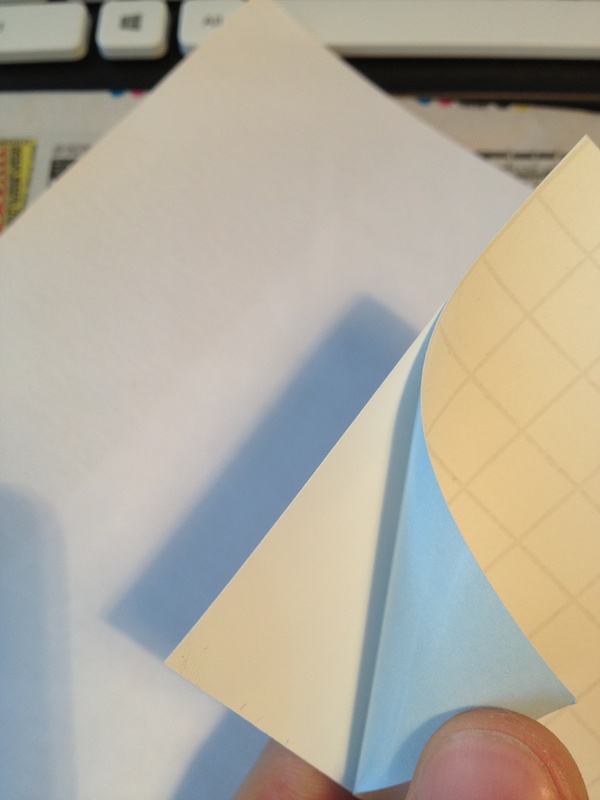
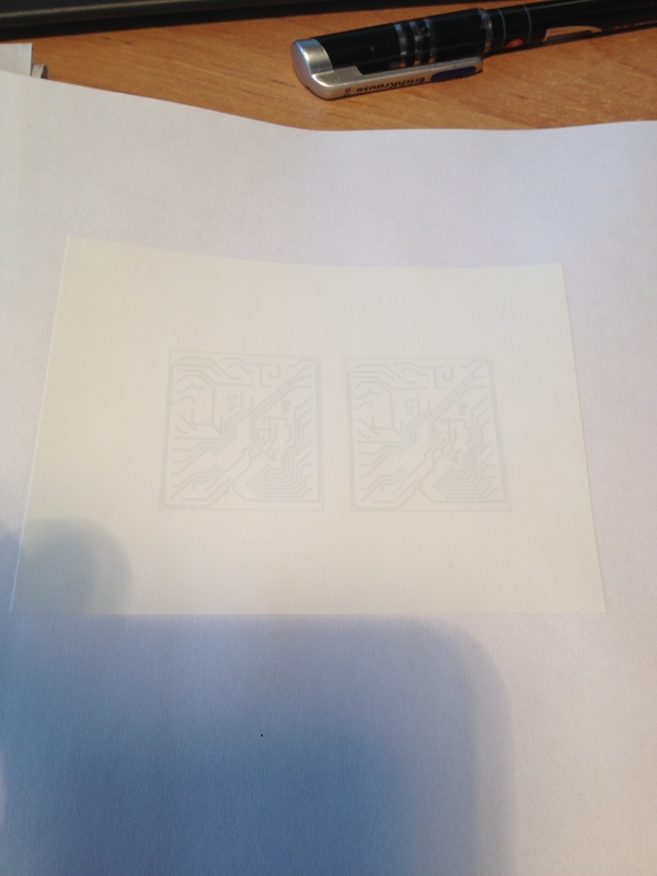
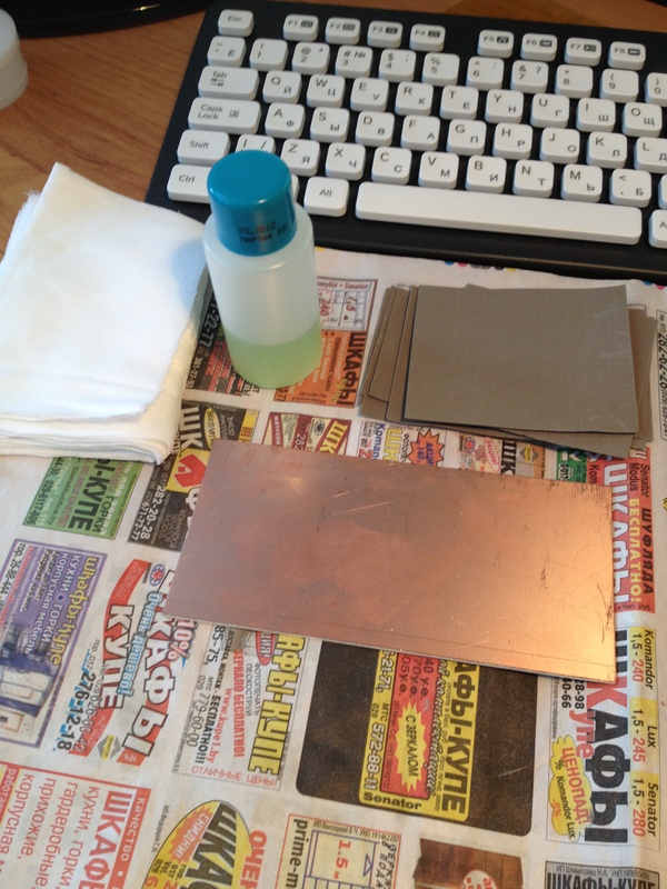
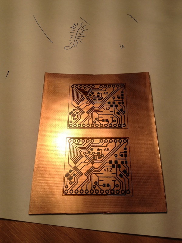
For a start, I print the board on plain A4 paper, then, using the light, I stick a piece of vinyl on it.
And typing again (do not forget to turn off all the options to save toner).
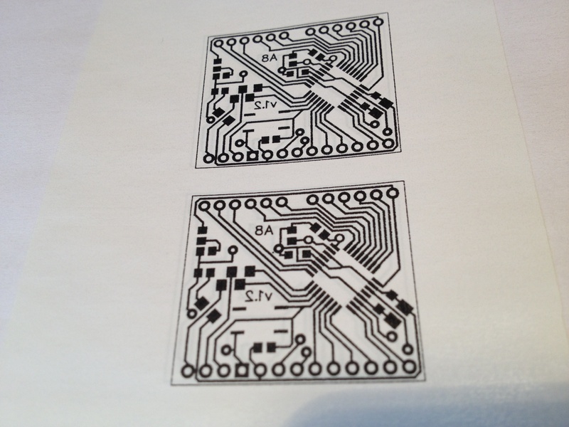
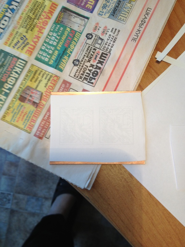
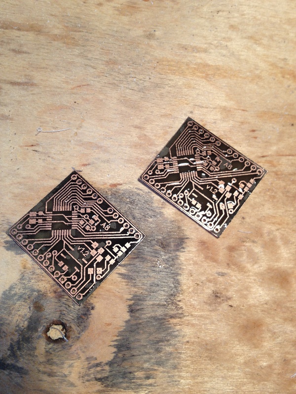
We clean the printed circuit board and impose the printed image.
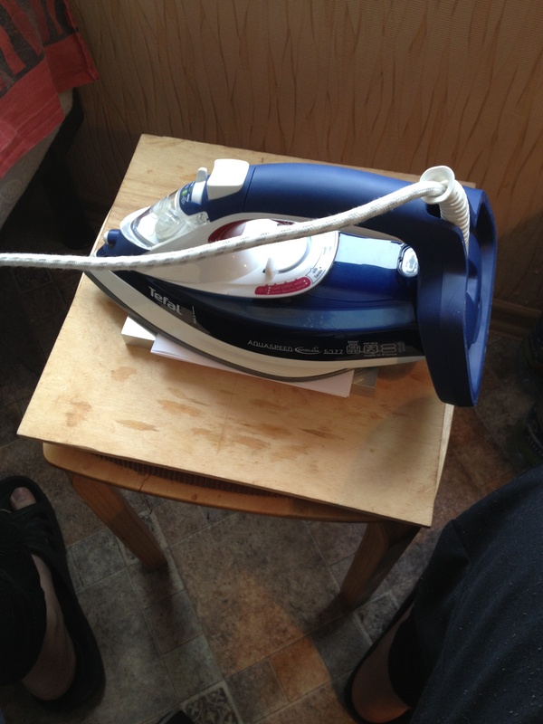
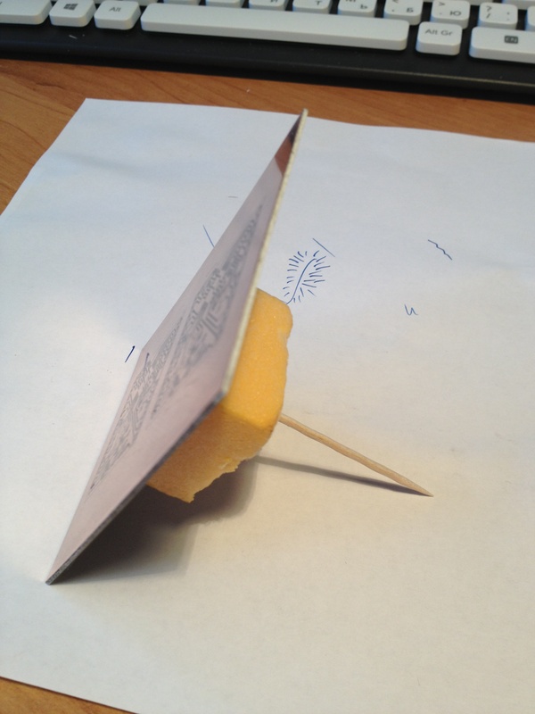
Ironing the toner is done according to the standard scheme: the board is inserted into a paper “envelope” for pressure distribution, it makes sense to put a metal object under the convet to remove heat, then we simply press the hot duck (I set the temperature to maximum) to the board for 10-15 seconds , gently smooth the edges of the board and ready.
The blank should be cooled in cold or warm water, this will help soften the paper used as the substrate.
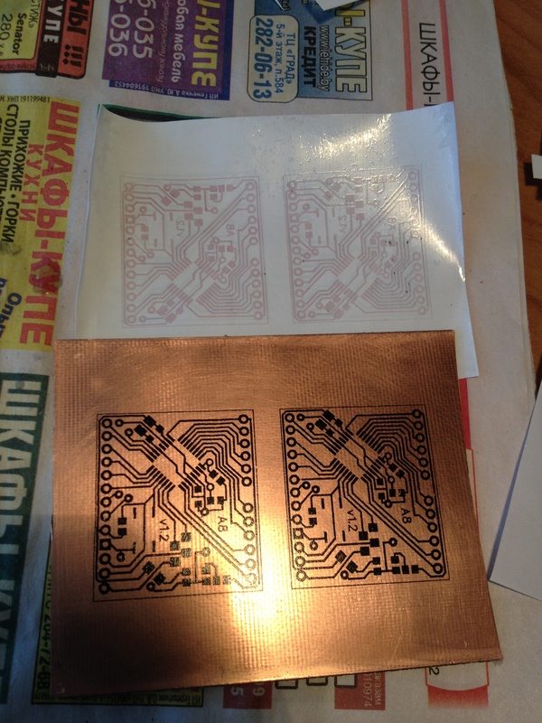
Further, it will be very pleasing for those who like to print using photo paper - there is no need to put a few minutes over the board, erasing pieces of paper and clearing tracks, vinyl is removed without a murmur and leaves no traces. The first time I was even surprised at such a black toner. :)


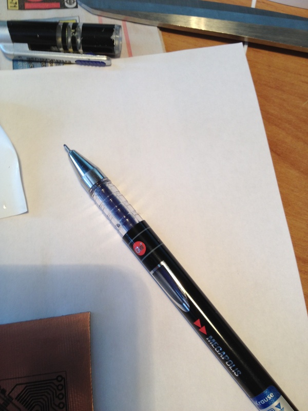
I use an ordinary gel pen to retouch badly translated tracks. Permanent marker for these purposes fits much better, but the pen turns out to be more accurate (even the tracks of 0.3-0.2 mm tint without problems). The peculiarity of this method is that the gel dries long enough, so either wait, or look for a hair dryer. :)
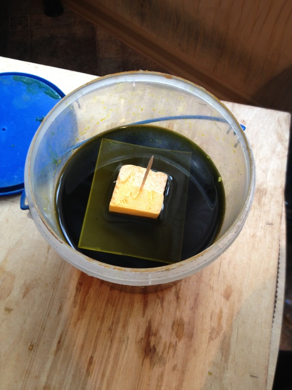
The solution used is heated ferric chloride, the board is “face down”. To speed up the etching process, the workpiece should be periodically shaken. Previously, for me, this work was done by a vibro-motor from a Nokia phone, but, in my carelessness, he died a brave death and dissolved .


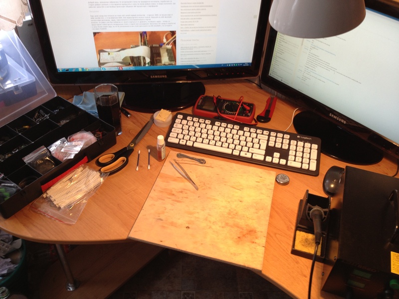
During pickling, you should clean up the workplace and prepare for soldering and drilling.
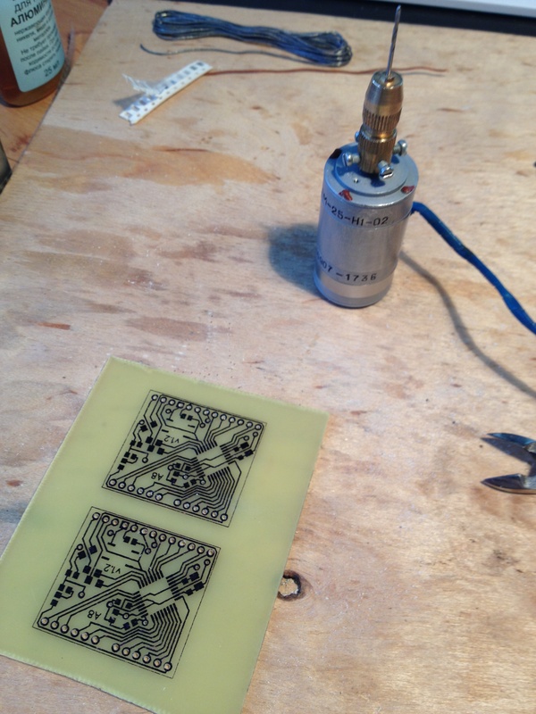
Finding a 24-volt home for a motor turned out to be problematic, I had to overclock the standard 5 using the MC34063 chip (for more information, at easyelectronics.ru ).

Testolite is quite thin, easy to cut with scissors.

Either because of a bad solvent or because of the properties of the PCB (which is more likely) I could not get to clean the toner without leaving stains on the board, it looks very messy and leaves an unpleasant feeling in my heart. After much deliberation, I decided not to fight the problem, but to use it for my own benefit. Paint the board with a marker that is not suitable for tint tracks. After wash off excess acetone.


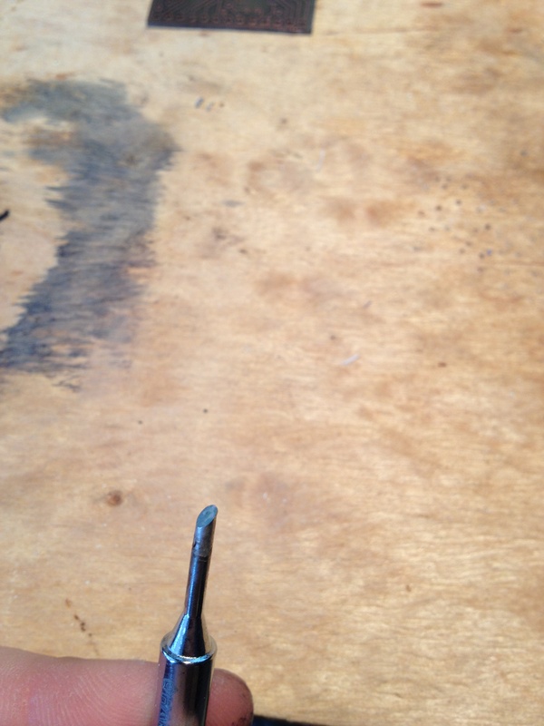
For tinning, we need a thick sting and a lot of flux. :)
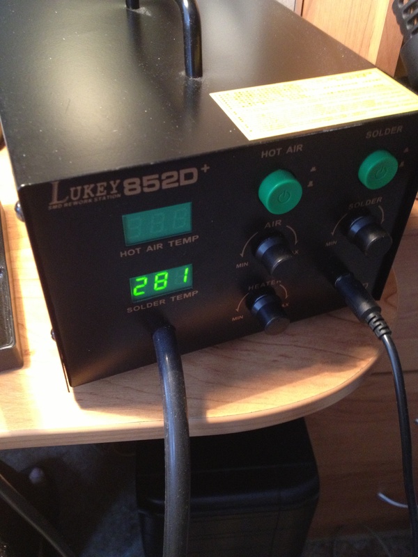
You can solder SMD components in many ways (with a simple soldering iron, in a stove, on a spotlight, etc.), I prefer to use a hairdryer (it’s good to buy a good soldering station without problems and for little money).
Using a thin beveled tip, we apply some solder to the places where our components will be located. In essence, this is a simple replacement for solder paste.

Tweezers place the components in the proper places.
We warm the board with a hairdryer, tweezers help the components look in the right direction.


I use twisted pair wire as jumpers, it is not very thick and holds its shape well.

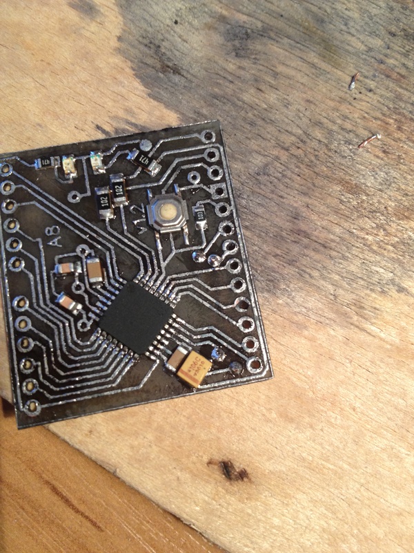
Almost finished product left to solder the legs. In order to eliminate distortions in the future, the board can be installed on the breadboard and soldered the side terminals.

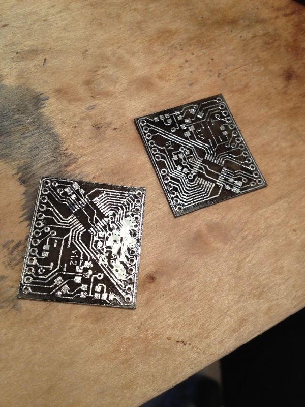
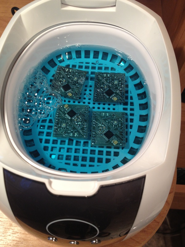
Done, the dirty work is over, now the boards need to be washed and stitched.
I use a conductive flux, you can wash it off with a toothbrush under a stream of warm water, or you can throw the boards in an ultrasonic bath and go and drink tea (the two lower boards were made earlier, I decided that it would not hurt an extra bath).
To turn a microcontroller on a piece of PCB into a full-fledged Arduin, we need to flash the bootloader, for this you can use any programmer, but for the sake of a single operation I take Arduin herself and the ArduinoISP sketch.

Any USB-UART adapter will be suitable for loading sketches, I personally soldered my own, with the reset line (the board will reboot itself during the loading of the sketch).

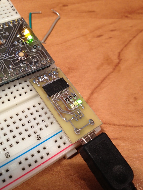

The adapter is made on the basis of FT232, the board is double-sided. Made the first time using the same vinyl (you need to combine the templates on the light and glue the edges).

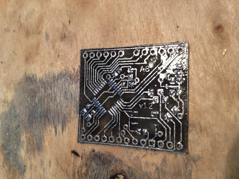
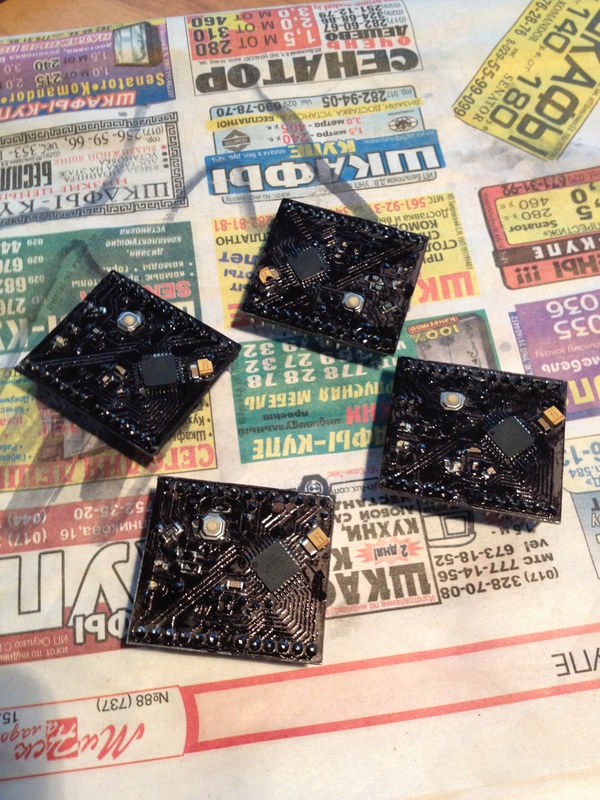
During washing and other operations, part of the black coating was washed away, so I repeated the painting already on the finished board.
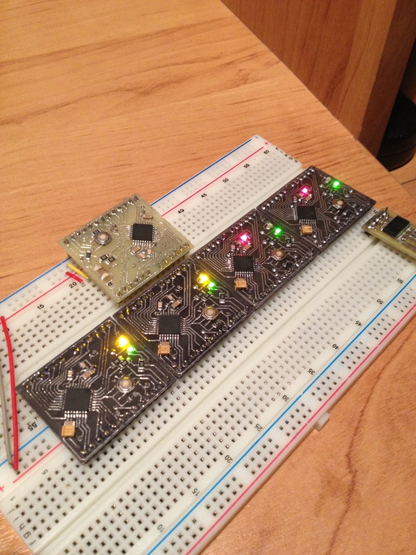
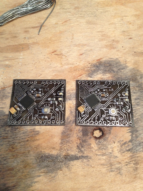
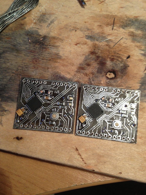
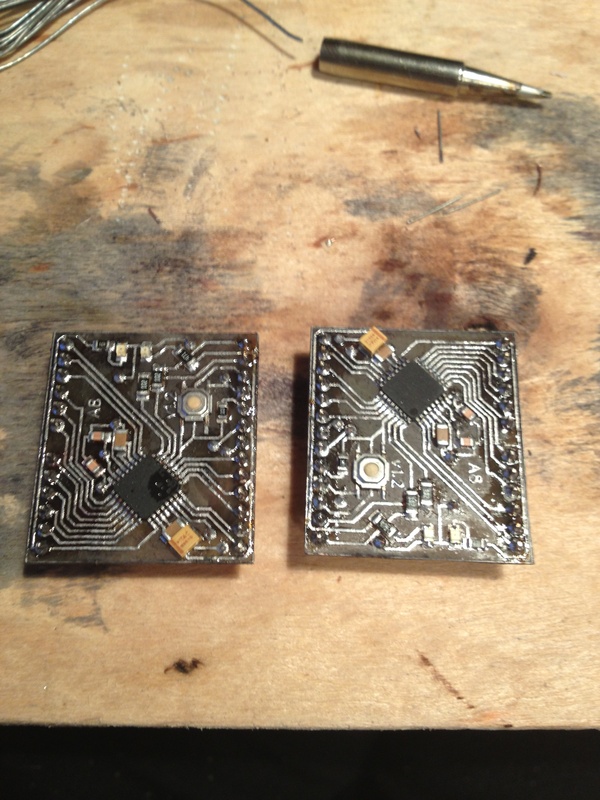
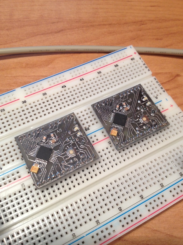
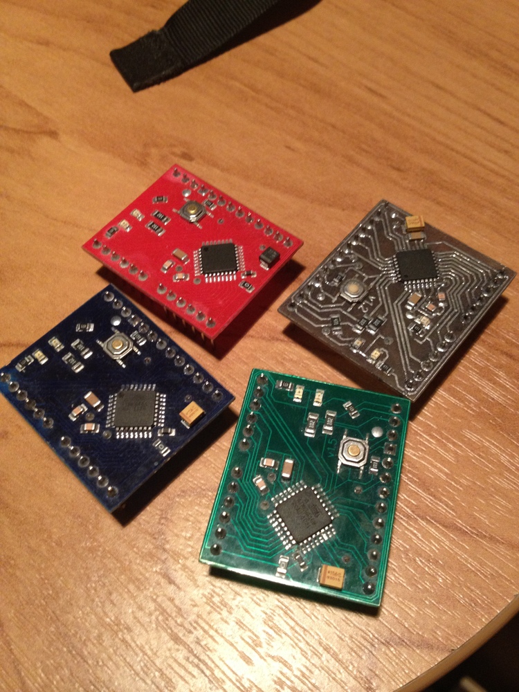
The finished product: there are two boards on the left on the ATMega8 , on the right there are two on the ATMega16 (the difference in the additional LED on the 5 (PWM) leg, you can smoothly adjust the brightness). The white crow on the top is the very first version of the board.
The thickness of the tracks is 0.33 mm, the outer border is 0.1 mm. The cost price of one board in the region of 2 dollars can be safely left in the finished device.
DipTrace board versions
PS For versions with ATMega168 , ATMega328 and higher, it is worth adding a choke to the AVCC leg, for ATMega8 it is useless, because The internal resistance between AVCC and VCC is about 6 ohms.
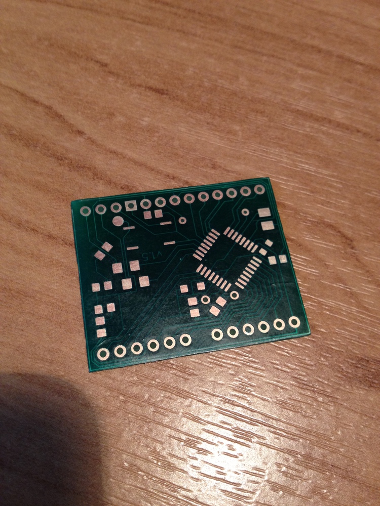
Using photoresistive technology and a one-component mask with eBay, you can achieve better results:
Vinyl favorably differs from photographic paper and various kinds of substrates - the process of making the board becomes less laborious and more economical, you can read about LUT itself here .
Content
- Print board
- Etching board (briefly)
- Drilling, cutting, "painting"
- Tinning (briefly)
- SMD component soldering
- Programming
- "Paint"
- Sources
⇑ Print board
To transfer the toner to the board, I will use the Oracal 651 vinyl (peeped here ). Oracal company is already known among radio amateurs for its basis for self-adhesive films, it is also suitable for LUT and has similar properties.
')
This material can be bought in companies engaged in printing on vinyl (advertising agencies, stickers, etc.), or ordered on ibee .
The most important advantage of this material is that it is self-adhesive .
This property allows us to use exactly as much vinyl as we need, without the need to throw away small pieces, and also does not require tricky manipulation to feed the printer.
As a result, we can safely make single devices of small size without worrying about the consumption of material.
For a start, I print the board on plain A4 paper, then, using the light, I stick a piece of vinyl on it.
And typing again (do not forget to turn off all the options to save toner).
We clean the printed circuit board and impose the printed image.
Ironing the toner is done according to the standard scheme: the board is inserted into a paper “envelope” for pressure distribution, it makes sense to put a metal object under the convet to remove heat, then we simply press the hot duck (I set the temperature to maximum) to the board for 10-15 seconds , gently smooth the edges of the board and ready.
The blank should be cooled in cold or warm water, this will help soften the paper used as the substrate.
Further, it will be very pleasing for those who like to print using photo paper - there is no need to put a few minutes over the board, erasing pieces of paper and clearing tracks, vinyl is removed without a murmur and leaves no traces. The first time I was even surprised at such a black toner. :)
I use an ordinary gel pen to retouch badly translated tracks. Permanent marker for these purposes fits much better, but the pen turns out to be more accurate (even the tracks of 0.3-0.2 mm tint without problems). The peculiarity of this method is that the gel dries long enough, so either wait, or look for a hair dryer. :)
⇑ Etching board
The solution used is heated ferric chloride, the board is “face down”. To speed up the etching process, the workpiece should be periodically shaken. Previously, for me, this work was done by a vibro-motor from a Nokia phone, but, in my carelessness, he died a brave death and dissolved .
During pickling, you should clean up the workplace and prepare for soldering and drilling.
⇑ Drilling, cutting, "painting"
Finding a 24-volt home for a motor turned out to be problematic, I had to overclock the standard 5 using the MC34063 chip (for more information, at easyelectronics.ru ).
Testolite is quite thin, easy to cut with scissors.
Either because of a bad solvent or because of the properties of the PCB (which is more likely) I could not get to clean the toner without leaving stains on the board, it looks very messy and leaves an unpleasant feeling in my heart. After much deliberation, I decided not to fight the problem, but to use it for my own benefit. Paint the board with a marker that is not suitable for tint tracks. After wash off excess acetone.
⇑ Tinning
For tinning, we need a thick sting and a lot of flux. :)
⇑ Soldering SMD components
You can solder SMD components in many ways (with a simple soldering iron, in a stove, on a spotlight, etc.), I prefer to use a hairdryer (it’s good to buy a good soldering station without problems and for little money).
Using a thin beveled tip, we apply some solder to the places where our components will be located. In essence, this is a simple replacement for solder paste.
Tweezers place the components in the proper places.
We warm the board with a hairdryer, tweezers help the components look in the right direction.
I use twisted pair wire as jumpers, it is not very thick and holds its shape well.
Almost finished product left to solder the legs. In order to eliminate distortions in the future, the board can be installed on the breadboard and soldered the side terminals.
Done, the dirty work is over, now the boards need to be washed and stitched.
I use a conductive flux, you can wash it off with a toothbrush under a stream of warm water, or you can throw the boards in an ultrasonic bath and go and drink tea (the two lower boards were made earlier, I decided that it would not hurt an extra bath).
⇑ Programming
To turn a microcontroller on a piece of PCB into a full-fledged Arduin, we need to flash the bootloader, for this you can use any programmer, but for the sake of a single operation I take Arduin herself and the ArduinoISP sketch.
Any USB-UART adapter will be suitable for loading sketches, I personally soldered my own, with the reset line (the board will reboot itself during the loading of the sketch).
The adapter is made on the basis of FT232, the board is double-sided. Made the first time using the same vinyl (you need to combine the templates on the light and glue the edges).
⇑ Step back
During washing and other operations, part of the black coating was washed away, so I repeated the painting already on the finished board.
⇑ End
The finished product: there are two boards on the left on the ATMega8 , on the right there are two on the ATMega16 (the difference in the additional LED on the 5 (PWM) leg, you can smoothly adjust the brightness). The white crow on the top is the very first version of the board.
The thickness of the tracks is 0.33 mm, the outer border is 0.1 mm. The cost price of one board in the region of 2 dollars can be safely left in the finished device.
DipTrace board versions
PS For versions with ATMega168 , ATMega328 and higher, it is worth adding a choke to the AVCC leg, for ATMega8 it is useless, because The internal resistance between AVCC and VCC is about 6 ohms.
UPD 04/21/2013
Using photoresistive technology and a one-component mask with eBay, you can achieve better results:
Source: https://habr.com/ru/post/161947/
All Articles