STM32 + linux
To develop a control system for one piece of iron after a long search, I chose an ARM microcontroller of the STM32 family - STM32F103 (in the “boneless” version). And as a model for development and debugging - STM32P103 (there are fewer legs, but the core is the same). “Success stories” I gradually laid out in my ZHshke, but now I decided to put everything together and tell about what it is - to program microcontrollers in Linux. The project itself lies at sourceforge .
First of all I will touch on the general, and then I will go on to the details.
')
So, in addition to the layout (or the finished device - when it is ready) you will need a JTAG adapter. In my case, this is ST-LINK / V2. Naturally, iron alone is not enough: you have to somehow somehow compile the code, and then also upload it to the controller. For this, the gcc compiler for ARM (arm-none-eabi) and the utility for working with ST-LINK were installed (it is called stlink).
As a sample, I took this project . From here I downloaded simple demo projects and tried to compile the simplest one. And the very first one turned out to be the standard Helloworld for the MC: blinking LED.
I'll tell you right away what rake I ran into from the very beginning: I forgot about objcopy, without which getting a working code would be difficult. After compiling the project, it is necessary to create a binary with this utility. And do not throw out incomprehensible (and seemingly even unnecessary at first glance) goals from the Makefiles.
I use Geany as a convenient IDE. Since I have two monitors at work, it’s quite convenient to work: I have Geany with the code on one monitor, and a terminal on the second, where I run make and com (the terminal from tinyserial).
I will not consider the whole Makefile, I will only pay attention to the fact that it should be changed:
After the code is written, run make. If everything is in order, the $ (BIN) .bin file will appear in the current directory, which you need to write to the MKshka flash memory. Writing is done with make load: this build target simply calls st-flash to flash the microcontroller.
So, first of all, it is necessary to establish a connection between the computer and MKshki. Considering the fact that there is no RS-232 in modern computers, I arrange the debug connection via USB. However, in the “battle conditions” the team will receive the RS-232 from another controller, so I decided to immediately look towards the organization of the USB <-> RS-232 adapter emulator. This approach is also convenient because you don’t have to bother with the extra code to interact with the device via USB (although this is elementary, but laziness is the same!). And it's easy to debug: open the device / dev / ttyACM0 as a serial port with the help of any serial terminal emulator and “communicate”. Yes, I used tinyserial as a terminal emulator at first (as long as there is no software on the computer side).
From here I downloaded the USB <-> RS-232 adapter emulator code. Since I couldn’t immediately check the operation of the second side (RS-232) (I have nowhere to connect), the unused code for working with USART was temporarily commented.
To work with USB, a library from STMicroelectronics is used. If you don’t delve into the library’s codes, it's pretty simple: we need to redefine the descriptors for our hardware (usb_desc. [Ch] files) so that the computer recognizes it as a USB <-> RS-232 adapter, and also change the interrupt handlers to USB events (at a minimum - process the received data, and for transparent operation as an adapter, you will need to add USART interrupt handling to transfer the data received from there via USB).
To send messages, we use something like a ring buffer, which will gradually be filled, and, if necessary, transferred via USB. We will read the data in the “normal buffer”. As long as I use only short commands, I did not bother with handling long parcels. If they are, it will be necessary to complicate the interrupt handler for receiving data from USB.
Since some commands (for example, reading the temperature from 1-wire sensors) take quite a long time, the handler of the commands received via USB only modifies the flags for such operations, and the main loop in main () processes these flags. Operations that are performed quickly (working with the LED) are called directly from this function. For debugging purposes, I added an “echo” to the commands in the form of a brief decryption:
That's it, now when I connect the layout to the computer via USB (and, actually, I always have it connected, because it is powered via USB) the device / dev / ttyACM0 appears, with which you can work as with a normal serial port. For example, open it with a serial terminal (as I said above, I use tinyserial at first).
Probably, it is traditional to “flash the diode” at the beginning of the study of some new piece of hardware, so I will do the same. And at the same time I will hang an interrupt on the “user button”, which will change the modes of the LED.
Just blinking is not interesting: it is interesting to change the brightness. For this, a simple "soft" ShIM is enough. Set the SysTick timer for a period of 10µs. Let's start two counters: one for the number of “ticks” during which the LED is on, and the second for the number of “ticks” during which the LED is off. To change the brightness of the LED, I made the simplest eight-level scheme for changing the PWM duty cycle.
It turned out this:
On the "custom button" I hung external interrupt:
And its handler is engaged in switching the LED to the continuous glow mode, if it blinked, or vice versa, to the blink mode, if it was glowing:
I pulled the code for working with 1-wire from easyelectronics.com from somewhere . I changed it quite a bit. First of all, I changed the search function for devices hanging on the bus (for some reason it did not work in the original, although the logic seemed to be quite clear and correct).
In the example I stole, 1-wire worked via USART, and DMA was used for reading / writing. I really liked this idea, so I used exactly this method (although it was possible to organize the 1-wire software protocol).
The standard scheme for connecting 1-wire bus to a serial port implies the presence of a Schottky diode:
However, I did not have such a diode. But I saw that in addition to the push-pull mode, the foot responsible for USART_TX can be switched to open drain mode - in this case there will be no short circuit. I used USART3 to work with 1-wire (while I indulge, I have enough legs, so I don’t need to do remap). In the diagram, I saw that the legs of USART3 (PB10 and PB11) were already pulled to the ground through resistors of 10 kOhm, so I didn’t even need to solder a resistor: I just soldered a small handkerchief with sockets on the breadboard so that it was convenient to connect thermal sensors.
I will not describe in detail the contents of the onewire.c file: this has already been done several times before me, and I will only touch directly on working with thermometers.
To monitor the temperature of the warm (above -50 ° C) parts of the device, I decided to use simple DS18S20 sensors (the stated measurement accuracy is at least 0.5 ° C). I connected the socket soldered to the breadboard to the right pins so that you can connect a couple of thermometers to the CK at the same time.
Here, for example, what I get when working with thermometers:
For starters, I marked all the thermometers to know which one I had. And after that I decided to see if their readings differ greatly. Temperature - the first two bytes of the sensor response. The seventh byte is the “remainder” of the temperature conversion embedded in the ADC thermometer. According to the documentation on the sensors, this residue helps to clarify the temperature value. However, it turned out that the sense of it - as from a goat milk.
In the process, the sensor heats up itself, which affects the measurement results. Therefore, do not interrogate them too often. In addition, the readings of the sensors differed from each other up to one and a half degrees! This must be borne in mind: if you plan to use several sensors so that you can monitor the temperature difference between areas of something with an accuracy not worse than 0.5 ° C, you must first calibrate all the sensors. And readings on the calibration formulas, and not the response of the sensors.
The real error of the sensor sometimes exceeds 0.5 ° C, so it’s still better to assume that the sensor has an accuracy of 1 ° C.
Hall sensors I have analog - SS495A. Sensor specifications can be found on the Internet. Let me just say that in its normal state, the voltage on its output leg is about 2.5V (logical unit STM32), depending on the polarity and the external magnetic field, it will change its readings within 0..5V. Considering that the output voltage can reach five volts, it is necessary to use not the usual, but “five-volt” (marked as FR in the specification) inputs of the controller.
The magnets I have (especially for this sensor), when placing their working surface within 1 mm from the sensor “muzzle” (marked side), led to the appearance of zero voltage at its output. Moreover, the level of logical zero appears in a rather small area along the coordinates in the parallel marked side of the sensor plane, i.e. positioning accuracy is pretty decent.
For the experiments I soldered one sensor on the breadboard. The power supply connected it to 5V, and the signal output brought to the PC10 port, which does not burn if 5V is supplied to it. In order not to constantly pull the port, I hung up an interrupt on it (by analogy with a button). The interrupt handler simply sets the corresponding flag, and in the main loop, if this flag is set (ie, the magnet either appears or leaves the sensor's “field of view”), we check that we have PC10. If there is zero (there is an MP), we write to the Magnet terminal, otherwise we write “clear”. You can also forcefully check whether there is a sensor or not by pressing “h” in the terminal.
In addition to the "warm zones" I still need to measure the temperature in the cold (up to 75K above). For this, platinum thermistors connected to the ADG506A analog switch will be used. Well, of course, I wondered how bad the “native” ADC of the MKshka: could it be used to measure the temperature?
There are plenty of examples of STM32 with ADC, I took an example from STDPeriphLib. We will run the ADC in continuous conversion mode, and store the result in memory using DMA. I set the conversion time to the largest (to be more precise), and for the time being, I’ll hang the PB0 (ADC8) on the foot of the ADC:
To work with the switch, you need to configure five bits of the control port. In order not to bathe with the conversion of bits, I simply took the first four bits of port C as the address, and the fifth bit as the key that includes the switch:
There are no interruptions here, and in the interrupts.c file, it is necessary to add the setting of a new flag when a command (say, the 'a' command) arrives to display the voltage on the sensors. In the main () add processing this flag:
When a command is received in a cycle, we start setting the required address on the switch, wait a couple of milliseconds for the ADC to work, and then output the resulting value. Then turn off the switch and wait (just in case) a couple of milliseconds.
On a separate layout I assembled a simple resistive voltage divider, connecting all the analog inputs of the switch with small-impedance (200..900 Ohm) resistors. I connected “ground” to S1, and to S16 - + 3.3V from the STM32 model. I powered up the chip with an old power supply from an external HDD (12V).
In the STM32P103 layout, the reference voltage for the ADC is taken from the total power, so the accuracy is low: sometimes the values float by as much as 20 units!
Here, for example, what happened with two surveys:
In general, it will be necessary either to try to add a stable source of reference voltage (and to feed the measured circuit from the same place), or to use an external ADC in general. Given the low resistance of the sensors to be used, you still have to solder the amplifier.
I haven’t finished messing around since I suspect that when I install elements on a breadboard, nothing will “fly up” from me. Need to solder. And I will probably do soldering only next year (I still need to buy radio components). So far, only briefly tell you how I plan to manage the stepper motors.
I will have sharks - 1.2 amps VSS42. Manage such most conveniently using the driver SD - L6208. When working on this chip, it is necessary to send only signals to control the direction of movement, a work enable signal and clock pulses. The controller itself adjusts the PWM and sets the required voltages on the motor windings.
I will point out the main things for now:
First of all I will touch on the general, and then I will go on to the details.
')
So, in addition to the layout (or the finished device - when it is ready) you will need a JTAG adapter. In my case, this is ST-LINK / V2. Naturally, iron alone is not enough: you have to somehow somehow compile the code, and then also upload it to the controller. For this, the gcc compiler for ARM (arm-none-eabi) and the utility for working with ST-LINK were installed (it is called stlink).
As a sample, I took this project . From here I downloaded simple demo projects and tried to compile the simplest one. And the very first one turned out to be the standard Helloworld for the MC: blinking LED.
I'll tell you right away what rake I ran into from the very beginning: I forgot about objcopy, without which getting a working code would be difficult. After compiling the project, it is necessary to create a binary with this utility. And do not throw out incomprehensible (and seemingly even unnecessary at first glance) goals from the Makefiles.
I use Geany as a convenient IDE. Since I have two monitors at work, it’s quite convenient to work: I have Geany with the code on one monitor, and a terminal on the second, where I run make and com (the terminal from tinyserial).
I will not consider the whole Makefile, I will only pay attention to the fact that it should be changed:
Code
BIN=testproject … STM32_LIBSRC+=stm32_lib/misc.c STM32_LIBSRC+=stm32_lib/stm32f10x_adc.c #~ STM32_LIBSRC+=stm32_lib/stm32f10x_bkp.c #~ STM32_LIBSRC+=stm32_lib/stm32f10x_can.c #~ STM32_LIBSRC+=stm32_lib/stm32f10x_cec.c #~ STM32_LIBSRC+=stm32_lib/stm32f10x_crc.c #~ STM32_LIBSRC+=stm32_lib/stm32f10x_dac.c #~ STM32_LIBSRC+=stm32_lib/stm32f10x_dbgmcu.c STM32_LIBSRC+=stm32_lib/stm32f10x_dma.c STM32_LIBSRC+=stm32_lib/stm32f10x_exti.c #~ STM32_LIBSRC+=stm32_lib/stm32f10x_flash.c #~ STM32_LIBSRC+=stm32_lib/stm32f10x_fsmc.c STM32_LIBSRC+=stm32_lib/stm32f10x_gpio.c #~ STM32_LIBSRC+=stm32_lib/stm32f10x_i2c.c #~ STM32_LIBSRC+=stm32_lib/stm32f10x_it.c #~ STM32_LIBSRC+=stm32_lib/stm32f10x_iwdg.c #~ STM32_LIBSRC+=stm32_lib/stm32f10x_pwr.c STM32_LIBSRC+=stm32_lib/stm32f10x_rcc.c #~ STM32_LIBSRC+=stm32_lib/stm32f10x_rtc.c #~ STM32_LIBSRC+=stm32_lib/stm32f10x_sdio.c #~ STM32_LIBSRC+=stm32_lib/stm32f10x_spi.c #~ STM32_LIBSRC+=stm32_lib/stm32f10x_tim.c STM32_LIBSRC+=stm32_lib/stm32f10x_usart.c #~ STM32_LIBSRC+=stm32_lib/stm32f10x_wwdg.c … SRC=hw_config.c main.c leds.c interrupts.c usb_desc.c usb_istr.c \ usb_prop.c usb_pwr.c onewire.c … #~ OBJ+=stm32f10x_bkp.o #~ OBJ+=stm32f10x_can.o #~ OBJ+=stm32f10x_cec.o #~ OBJ+=stm32f10x_crc.o #~ OBJ+=stm32f10x_dac.o #~ OBJ+=stm32f10x_dbgmcu.o OBJ+=stm32f10x_dma.o OBJ+=stm32f10x_exti.o #~ OBJ+=stm32f10x_flash.o #~ OBJ+=stm32f10x_fsmc.o OBJ+=stm32f10x_gpio.o #~ OBJ+=stm32f10x_i2c.o #~ OBJ+=stm32f10x_it.o #~ OBJ+=stm32f10x_iwdg.o #~ OBJ+=stm32f10x_pwr.o OBJ+=stm32f10x_rcc.o #~ OBJ+=stm32f10x_rtc.o #~ OBJ+=stm32f10x_sdio.o #~ OBJ+=stm32f10x_spi.o #~ OBJ+=stm32f10x_tim.o OBJ+=stm32f10x_usart.o #~ OBJ+=stm32f10x_wwdg.o - BIN - the name of the resulting binary after compilation
- STM32_LIBSRC and OBJ contain the included STDPeriphLib library files that should not be used are commented out.
- SRC maintains a list of custom sources
After the code is written, run make. If everything is in order, the $ (BIN) .bin file will appear in the current directory, which you need to write to the MKshka flash memory. Writing is done with make load: this build target simply calls st-flash to flash the microcontroller.
USB
So, first of all, it is necessary to establish a connection between the computer and MKshki. Considering the fact that there is no RS-232 in modern computers, I arrange the debug connection via USB. However, in the “battle conditions” the team will receive the RS-232 from another controller, so I decided to immediately look towards the organization of the USB <-> RS-232 adapter emulator. This approach is also convenient because you don’t have to bother with the extra code to interact with the device via USB (although this is elementary, but laziness is the same!). And it's easy to debug: open the device / dev / ttyACM0 as a serial port with the help of any serial terminal emulator and “communicate”. Yes, I used tinyserial as a terminal emulator at first (as long as there is no software on the computer side).
From here I downloaded the USB <-> RS-232 adapter emulator code. Since I couldn’t immediately check the operation of the second side (RS-232) (I have nowhere to connect), the unused code for working with USART was temporarily commented.
To work with USB, a library from STMicroelectronics is used. If you don’t delve into the library’s codes, it's pretty simple: we need to redefine the descriptors for our hardware (usb_desc. [Ch] files) so that the computer recognizes it as a USB <-> RS-232 adapter, and also change the interrupt handlers to USB events (at a minimum - process the received data, and for transparent operation as an adapter, you will need to add USART interrupt handling to transfer the data received from there via USB).
To send messages, we use something like a ring buffer, which will gradually be filled, and, if necessary, transferred via USB. We will read the data in the “normal buffer”. As long as I use only short commands, I did not bother with handling long parcels. If they are, it will be necessary to complicate the interrupt handler for receiving data from USB.
Since some commands (for example, reading the temperature from 1-wire sensors) take quite a long time, the handler of the commands received via USB only modifies the flags for such operations, and the main loop in main () processes these flags. Operations that are performed quickly (working with the LED) are called directly from this function. For debugging purposes, I added an “echo” to the commands in the form of a brief decryption:
Code
void usb_handle_command(uint16_t cnt){ uint8_t command, *answer; uint16_t i; for(i = 0; i < cnt; i++){ command = USB_Rx_Buffer[i]; switch(command){ case CMD_LED_ON: LED_On(); answer = (uint8_t*)"On"; break; case CMD_LED_OFF: LED_Off(); answer = (uint8_t*)"Off"; break; case CMD_LED_BLINK: LED_OnBlink(); answer = (uint8_t*)"Blk"; break; case CMD_LED_DUTY_PLUS: LED_DutyPlus(); answer = (uint8_t*)"Shn"; break; case CMD_LED_DUTY_MINUS: LED_DutyMinus(); answer = (uint8_t*)"Fad"; break; case CMD_1W_GET_TEMP: FLAGS |= FLAG_READ_T; answer = (uint8_t*)"Read T"; break; case CMD_1W_GET_DEV: FLAGS |= FLAG_GETDEV; answer = (uint8_t*)"find devices"; break; case CMD_1W_PRNT_DEV: FLAGS |= FLAG_PRINTDEV; answer = (uint8_t*)"Print devices"; break; case CMD_HALL_GET: FLAGS |= FLAG_PRINTHALL; answer = (uint8_t*)"Print Hall"; break; case CMD_ADC_GET: FLAGS |= FLAG_PRINTADC; answer = (uint8_t*)"Print ADC val"; break; default: answer = (uint8_t*)"Unk"; } newline(); prnt(answer); newline(); } } That's it, now when I connect the layout to the computer via USB (and, actually, I always have it connected, because it is powered via USB) the device / dev / ttyACM0 appears, with which you can work as with a normal serial port. For example, open it with a serial terminal (as I said above, I use tinyserial at first).
LED, button
Probably, it is traditional to “flash the diode” at the beginning of the study of some new piece of hardware, so I will do the same. And at the same time I will hang an interrupt on the “user button”, which will change the modes of the LED.
Just blinking is not interesting: it is interesting to change the brightness. For this, a simple "soft" ShIM is enough. Set the SysTick timer for a period of 10µs. Let's start two counters: one for the number of “ticks” during which the LED is on, and the second for the number of “ticks” during which the LED is off. To change the brightness of the LED, I made the simplest eight-level scheme for changing the PWM duty cycle.
It turned out this:
Code
uint8_t LED_GetState(){ return led_state; } void LED_Duty(uint8_t duty){ duty_cycle = duty; if(led_state == LEDSTATE_BLINK) LED_OnBlink(); } void LED_DutyPlus(){ if(duty_cycle < 7) duty_cycle++; if(led_state == LEDSTATE_BLINK) LED_OnBlink(); } void LED_DutyMinus(){ if(duty_cycle > 0) duty_cycle--; if(led_state == LEDSTATE_BLINK) LED_OnBlink(); } uint8_t LED_GetBlinkState(uint16_t *blink_on, uint16_t *blink_off){ *blink_on = led_blink_on; *blink_off = led_blink_off; return led_state; } void LED_On(){ led_state = LEDSTATE_ON; led_blink_on = 0; led_blink_off = 0; GPIO_ResetBits(GPIOC, GPIO_Pin_12); } void LED_Off(){ led_state = LEDSTATE_OFF; GPIO_SetBits(GPIOC, GPIO_Pin_12); } void LED_OnBlink(){ led_blink_off = 1 << duty_cycle; led_blink_on = 0xff - led_blink_off; led_ticks_on = 0; led_ticks_off = 0; if(led_blink_off == 0){ LED_On(); return; } if(led_blink_on == 0) { LED_Off(); return; } led_state = LEDSTATE_BLINK; } void LED_SysTick_Handler(){ if(led_state != LEDSTATE_BLINK) return; if(led_ticks_on == 0) GPIO_SetBits(GPIOC, GPIO_Pin_12); if(led_ticks_on <= led_blink_on) { led_ticks_on++; return; } if (led_ticks_off == 0){ GPIO_ResetBits(GPIOC, GPIO_Pin_12); } if(led_ticks_off <= led_blink_off){ led_ticks_off++; return; } led_ticks_on = 0; led_ticks_off = 0; } On the "custom button" I hung external interrupt:
Code
// Enable the BUTTON Clock RCC_APB2PeriphClockCmd(RCC_APB2Periph_AFIO, ENABLE); RCC_APB2PeriphClockCmd(RCC_APB2Periph_GPIOA, ENABLE); // Configure Button pin as input GPIO_InitStructure.GPIO_Mode = GPIO_Mode_IN_FLOATING; GPIO_InitStructure.GPIO_Pin = GPIO_Pin_0; GPIO_InitStructure.GPIO_Speed = GPIO_Speed_2MHz; GPIO_Init(GPIOA, &GPIO_InitStructure); // Connect Button EXTI Line to Button GPIO Pin GPIO_EXTILineConfig(GPIO_PortSourceGPIOA, GPIO_PinSource0); // Configure Button EXTI line EXTI_InitStructure.EXTI_Line = EXTI_Line0; EXTI_InitStructure.EXTI_Mode = EXTI_Mode_Interrupt; EXTI_InitStructure.EXTI_Trigger = EXTI_Trigger_Rising; EXTI_InitStructure.EXTI_LineCmd = ENABLE; EXTI_Init(&EXTI_InitStructure); // Enable and set Button EXTI Interrupt to the lowest priority NVIC_InitStructure.NVIC_IRQChannel = EXTI0_IRQn; NVIC_InitStructure.NVIC_IRQChannelPreemptionPriority = 0x0F; NVIC_InitStructure.NVIC_IRQChannelSubPriority = 0x0F; NVIC_InitStructure.NVIC_IRQChannelCmd = ENABLE; NVIC_Init(&NVIC_InitStructure); And its handler is engaged in switching the LED to the continuous glow mode, if it blinked, or vice versa, to the blink mode, if it was glowing:
Code
void EXTI0_IRQHandler(void){ if(EXTI_GetITStatus(EXTI_Line0) != RESET){ if(LED_GetState() != LEDSTATE_BLINK) LED_OnBlink(); else LED_On(); EXTI_ClearITPendingBit(EXTI_Line0); } } 1-wire
I pulled the code for working with 1-wire from easyelectronics.com from somewhere . I changed it quite a bit. First of all, I changed the search function for devices hanging on the bus (for some reason it did not work in the original, although the logic seemed to be quite clear and correct).
In the example I stole, 1-wire worked via USART, and DMA was used for reading / writing. I really liked this idea, so I used exactly this method (although it was possible to organize the 1-wire software protocol).
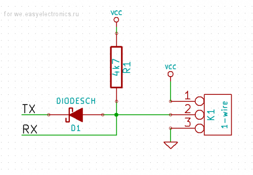
The standard scheme for connecting 1-wire bus to a serial port implies the presence of a Schottky diode:
However, I did not have such a diode. But I saw that in addition to the push-pull mode, the foot responsible for USART_TX can be switched to open drain mode - in this case there will be no short circuit. I used USART3 to work with 1-wire (while I indulge, I have enough legs, so I don’t need to do remap). In the diagram, I saw that the legs of USART3 (PB10 and PB11) were already pulled to the ground through resistors of 10 kOhm, so I didn’t even need to solder a resistor: I just soldered a small handkerchief with sockets on the breadboard so that it was convenient to connect thermal sensors.
I will not describe in detail the contents of the onewire.c file: this has already been done several times before me, and I will only touch directly on working with thermometers.
To monitor the temperature of the warm (above -50 ° C) parts of the device, I decided to use simple DS18S20 sensors (the stated measurement accuracy is at least 0.5 ° C). I connected the socket soldered to the breadboard to the right pins so that you can connect a couple of thermometers to the CK at the same time.
Here, for example, what I get when working with thermometers:
Code
com /dev/ttyACM0 Ca exit, Cx modem lines status [STATUS]: RTS CTS DTR // 'c' : find devices Found 2 devices // 'p' : Print devices device 0: 0x10 0x7c 0xee 0x8f 0x02 0x08 0x00 0x1c device 1: 0x10 0xad 0xbc 0x8f 0x02 0x08 0x00 0xf9 // 't' : Read T Device 0: 0x3b 0x00 0x4b 0x46 0xff 0xff 0x08 0x10 0x39 Device 1: 0x3a 0x00 0x4b 0x46 0xff 0xff 0x0c 0x10 0x41 For starters, I marked all the thermometers to know which one I had. And after that I decided to see if their readings differ greatly. Temperature - the first two bytes of the sensor response. The seventh byte is the “remainder” of the temperature conversion embedded in the ADC thermometer. According to the documentation on the sensors, this residue helps to clarify the temperature value. However, it turned out that the sense of it - as from a goat milk.
In the process, the sensor heats up itself, which affects the measurement results. Therefore, do not interrogate them too often. In addition, the readings of the sensors differed from each other up to one and a half degrees! This must be borne in mind: if you plan to use several sensors so that you can monitor the temperature difference between areas of something with an accuracy not worse than 0.5 ° C, you must first calibrate all the sensors. And readings on the calibration formulas, and not the response of the sensors.
The real error of the sensor sometimes exceeds 0.5 ° C, so it’s still better to assume that the sensor has an accuracy of 1 ° C.
Hall Sensor
Hall sensors I have analog - SS495A. Sensor specifications can be found on the Internet. Let me just say that in its normal state, the voltage on its output leg is about 2.5V (logical unit STM32), depending on the polarity and the external magnetic field, it will change its readings within 0..5V. Considering that the output voltage can reach five volts, it is necessary to use not the usual, but “five-volt” (marked as FR in the specification) inputs of the controller.
The magnets I have (especially for this sensor), when placing their working surface within 1 mm from the sensor “muzzle” (marked side), led to the appearance of zero voltage at its output. Moreover, the level of logical zero appears in a rather small area along the coordinates in the parallel marked side of the sensor plane, i.e. positioning accuracy is pretty decent.
For the experiments I soldered one sensor on the breadboard. The power supply connected it to 5V, and the signal output brought to the PC10 port, which does not burn if 5V is supplied to it. In order not to constantly pull the port, I hung up an interrupt on it (by analogy with a button). The interrupt handler simply sets the corresponding flag, and in the main loop, if this flag is set (ie, the magnet either appears or leaves the sensor's “field of view”), we check that we have PC10. If there is zero (there is an MP), we write to the Magnet terminal, otherwise we write “clear”. You can also forcefully check whether there is a sensor or not by pressing “h” in the terminal.
ADC
In addition to the "warm zones" I still need to measure the temperature in the cold (up to 75K above). For this, platinum thermistors connected to the ADG506A analog switch will be used. Well, of course, I wondered how bad the “native” ADC of the MKshka: could it be used to measure the temperature?
There are plenty of examples of STM32 with ADC, I took an example from STDPeriphLib. We will run the ADC in continuous conversion mode, and store the result in memory using DMA. I set the conversion time to the largest (to be more precise), and for the time being, I’ll hang the PB0 (ADC8) on the foot of the ADC:
Code
// 0. Configure ADC8 (PB0) as analog input (clocking GPIOB sat on in onewire.c) RCC_ADCCLKConfig(RCC_PCLK2_Div4); RCC_AHBPeriphClockCmd(RCC_AHBPeriph_DMA1, ENABLE); RCC_APB2PeriphClockCmd(RCC_APB2Periph_ADC1 | RCC_APB2Periph_GPIOB, ENABLE); GPIO_InitStructure.GPIO_Pin = GPIO_Pin_0; GPIO_InitStructure.GPIO_Mode = GPIO_Mode_AIN; GPIO_Init(GPIOB, &GPIO_InitStructure); // 1. DMA for converted value (DMA1 clocking sat on at onewire.c) //RCC_AHBPeriphClockCmd(RCC_AHBPeriph_DMA1, ENABLE); DMA_DeInit(DMA1_Channel1); DMA_InitStructure.DMA_PeripheralBaseAddr = ADC1_DR_Address; DMA_InitStructure.DMA_MemoryBaseAddr = (uint32_t)&ADC_value; DMA_InitStructure.DMA_DIR = DMA_DIR_PeripheralSRC; DMA_InitStructure.DMA_BufferSize = 1; DMA_InitStructure.DMA_PeripheralInc = DMA_PeripheralInc_Disable; DMA_InitStructure.DMA_MemoryInc = DMA_MemoryInc_Disable; DMA_InitStructure.DMA_PeripheralDataSize = DMA_PeripheralDataSize_HalfWord; DMA_InitStructure.DMA_MemoryDataSize = DMA_MemoryDataSize_HalfWord; DMA_InitStructure.DMA_Mode = DMA_Mode_Circular; DMA_InitStructure.DMA_Priority = DMA_Priority_High; DMA_InitStructure.DMA_M2M = DMA_M2M_Disable; DMA_Init(DMA1_Channel1, &DMA_InitStructure); DMA_Cmd(DMA1_Channel1, ENABLE); // 2. ADC1 config ADC_InitStructure.ADC_Mode = ADC_Mode_Independent; ADC_InitStructure.ADC_ScanConvMode = ENABLE; ADC_InitStructure.ADC_ContinuousConvMode = ENABLE; ADC_InitStructure.ADC_ExternalTrigConv = ADC_ExternalTrigConv_None; ADC_InitStructure.ADC_DataAlign = ADC_DataAlign_Right; ADC_InitStructure.ADC_NbrOfChannel = 1; ADC_Init(ADC1, &ADC_InitStructure); // Connect ADC to ADC8 (PB0), ADC_RegularChannelConfig(ADC1, ADC_Channel_8, 1, ADC_SampleTime_239Cycles5); // Enable ADC1 DMA ADC_DMACmd(ADC1, ENABLE); ADC_Cmd(ADC1, ENABLE); // Calibration of ADC1 ADC_ResetCalibration(ADC1); while(ADC_GetResetCalibrationStatus(ADC1)); ADC_StartCalibration(ADC1); while(ADC_GetCalibrationStatus(ADC1)); ADC_SoftwareStartConvCmd(ADC1, ENABLE); // turn conversion on To work with the switch, you need to configure five bits of the control port. In order not to bathe with the conversion of bits, I simply took the first four bits of port C as the address, and the fifth bit as the key that includes the switch:
Code
GPIO_InitStructure.GPIO_Pin = 0x1f; // first 5 bits of PC0 // PC0..PC3 - analog channel address, PC4 - analog enable switch GPIO_InitStructure.GPIO_Speed = GPIO_Speed_2MHz; GPIO_InitStructure.GPIO_Mode = GPIO_Mode_Out_PP; GPIO_Init(GPIOC, &GPIO_InitStructure); There are no interruptions here, and in the interrupts.c file, it is necessary to add the setting of a new flag when a command (say, the 'a' command) arrives to display the voltage on the sensors. In the main () add processing this flag:
Code
inline void prntADC(){ uint32_t address; // addr = 0, EN = 1 uint8_t *_2b = (uint8_t *) &ADC_value; for(address = 0x10; address < 0x20; address++){ // changhe channel address & turn on switch GPIOC->BSRR = address; Delay(2); // wait for AD conversion prnt((uint8_t*)"Temperature "); printInt(address&0x0f); prnt((uint8_t*)" = "); printInt(_2b[1]); printInt(_2b[0]); newline(); // turn off switch & reset bits GPIOC->BRR = (uint32_t)0x1f; Delay(2); } } When a command is received in a cycle, we start setting the required address on the switch, wait a couple of milliseconds for the ADC to work, and then output the resulting value. Then turn off the switch and wait (just in case) a couple of milliseconds.
On a separate layout I assembled a simple resistive voltage divider, connecting all the analog inputs of the switch with small-impedance (200..900 Ohm) resistors. I connected “ground” to S1, and to S16 - + 3.3V from the STM32 model. I powered up the chip with an old power supply from an external HDD (12V).
In the STM32P103 layout, the reference voltage for the ADC is taken from the total power, so the accuracy is low: sometimes the values float by as much as 20 units!
Here, for example, what happened with two surveys:
Code
// 1 Temperature 0x00 = 0x00 0x00 Temperature 0x01 = 0x00 0x84 Temperature 0x02 = 0x00 0xaf Temperature 0x03 = 0x01 0xdb Temperature 0x04 = 0x03 0x10 Temperature 0x05 = 0x03 0xe4 Temperature 0x06 = 0x05 0xca Temperature 0x07 = 0x06 0x9b Temperature 0x08 = 0x07 0x4e Temperature 0x09 = 0x08 0xd6 Temperature 0x0a = 0x0a 0x04 Temperature 0x0b = 0x0a 0xb4 Temperature 0x0c = 0x0b 0xfc Temperature 0x0d = 0x0d 0xe0 Temperature 0x0e = 0x0e 0xb7 Temperature 0x0f = 0x0f 0xff // 2 Temperature 0x00 = 0x00 0x00 Temperature 0x01 = 0x00 0x7f Temperature 0x02 = 0x00 0xaf Temperature 0x03 = 0x01 0xdf Temperature 0x04 = 0x03 0x0f Temperature 0x05 = 0x03 0xe4 Temperature 0x06 = 0x05 0xcc Temperature 0x07 = 0x06 0x9d Temperature 0x08 = 0x07 0x5a Temperature 0x09 = 0x08 0xd6 Temperature 0x0a = 0x0a 0x01 Temperature 0x0b = 0x0a 0xb5 Temperature 0x0c = 0x0b 0xfc Temperature 0x0d = 0x0e 0x09 Temperature 0x0e = 0x0e 0xb0 Temperature 0x0f = 0x0f 0xec In general, it will be necessary either to try to add a stable source of reference voltage (and to feed the measured circuit from the same place), or to use an external ADC in general. Given the low resistance of the sensors to be used, you still have to solder the amplifier.
Stepper motor
I haven’t finished messing around since I suspect that when I install elements on a breadboard, nothing will “fly up” from me. Need to solder. And I will probably do soldering only next year (I still need to buy radio components). So far, only briefly tell you how I plan to manage the stepper motors.
I will have sharks - 1.2 amps VSS42. Manage such most conveniently using the driver SD - L6208. When working on this chip, it is necessary to send only signals to control the direction of movement, a work enable signal and clock pulses. The controller itself adjusts the PWM and sets the required voltages on the motor windings.
I will point out the main things for now:
- The PWM adjustment is performed by comparing the voltage drop across the Sense resistors with the reference voltage Vref. Therefore, for the current I max and the resistance of the resistors R Sense, this drop can be calculated quite simply:
U ref = I max · R Sense
Those. to set the current limit to 1.2A with R Sense = 0.33Ohm, you must set U ref = 0.4 V. In no case can you leave the legs V ref hanging in the air or pressed to the ground! - Slow / Fast decay mode is important for conventional collector engines, while Fast decay is only needed in microstepping mode. In general, if you don’t pervert, you just need to apply + 5V per leg of CONTROL. On HALF / FULL, we also just serve + 5V and work in half-step mode. We do the same with the RESET leg, if we don’t want to reset the phase counter (and we don’t need to reset it, if we honestly give 8 sync pulses to each step).
- The ENABLE input is also an output: if a trouble occurs with the L6208 driver (overheating, current surge), it automatically disconnects the voltage on the load, and ENABLE pulls it to the ground. This means that it is possible to check whether an emergency has occurred, if the leg of the controller that controls the ENABLE port is activated in the open collector output mode.
According to the STM32 specification, in the open collector mode, when a unit is applied to the port output, the transistor tightening the leg to the ground is simply locked. If the output is zero, then the leg is tightened again.
Thus, pulling the controller's leg to + 5V ( FT should be chosen leg) through, say, a five-kilohm resistor, and between it and ENABLE, sticking, say, a kilohm resistor (and not forgetting to shunt the ENABLE leg with a capacitor to the ground , otherwise you can burn the control controller ), you can enable / disable the desired engine, and check if there were any accidents (and for this you can hang up the periphery of the periphery on the falling front of the controller on the falling front). - Conductors marked bold in the specification should be as short and wide as possible. But at the same time, care must be taken to reduce parasitic capacitances and inductances.
R Sense should be located as close as possible to the driver. Not far from them should be C and C₂ capacitors (according to the specification): not only the comparison current flows through this circuit, but also the reverse induction current (therefore, by the way, diodes cannot be included in this chain ).
C₁ , ( , , , , ). - : ! 5 .
, , : +5 . , , , 0. . . , USB-, , ...
Source: https://habr.com/ru/post/161863/
All Articles