Robot Loader Project: Determine Your Own Location
My long-time British partner (it was for him two years ago that “Recognition of postal addresses” was written) had a new idea to optimize business processes: robots had to carry boxes around the warehouse, and the loaders only to shift goods from the robot to the shelf and back. The point, naturally, is not to have a loader on each heel, and take up loading and unloading as soon as the robot stops - but that there are much more robots than movers and that robots most of the time were at the end point of their route, waiting for loading. Then the loader will only move from one robot to the next, loading each one, and will not spend working time carrying the goods.
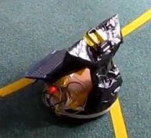 Last year, we experimented with the Roomba self-propelled vacuum cleaner platform. A new vacuum cleaner cost us around £ 300 (a used one can be found for £ 100 and even cheaper), and it consists of two electric drives for wheels, two touch sensors in front, an infrared sensor at the bottom (for detecting steps) and at the top (for searching for the station) . The exact list of sensors depends on the model: the protocol provides for up to four infrared sensors from the bottom, each of which returns one bit (“the floor is visible / not visible”). In any case, no range finders: all available sensors are one-bit. In addition, there are no “programmable arduins” in Roomba, and in order to control it, you need to install a laptop (or arduin) on top and communicate with the robot via RS-232. Having played enough with a vacuum cleaner, we left it gathering dust on one of the shelves of the warehouse.
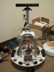 This year we decided to try Microsoft Robotics Development Studio (MRDS) , to promote which Microsoft formulated the “MRDS Reference Platform” specification - a set of equipment and a control protocol for a “standard” robot. This specification would allow robots to create compatible robots and transfer programs between them. Compared with the hardware of the vacuum cleaner, the Reference Platform is much more complicated and powerful: Kinect is included in the specification, three IR rangefinders and two ultrasonic, and also wheel rotation sensors (encoders). The implementation of the MRDS RP is currently offered only by the company Parallax called Eddie (about £ 1000, not including Kinect). The extraordinary similarity of Eddie with the photos of the prototype robot in the MRDS RP specification suggests that the specification was created in close cooperation with Parallax, in other words, Parallax managed to achieve that Microsoft took their platform as a reference.
')
In addition to the variety of sensors, the Eddie has a mechanically impressive platform (declared load capacity of 20kg, and the power of the motors is enough to push the warehouse loader ahead of itself) and the programmable Parallax Propeller controller, i.e. Critical pieces of code can be sewn directly into the robot, and not just command it from a computer.
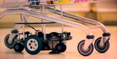
 The British Channel 4 included a two-minute piece with the Eddie demo integrated into a shopping cart in one of the releases of the Gadget Man program. Unfortunately, only the owners of British IP addresses can view the program on Channel 4, and I did not manage to grab it and reload it (maybe someone of the readers will succeed?) - therefore I bring only freeze-frames from there.
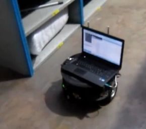
Just control the robot "forward-back-left-right" - nothing tricky, and the program of such "remote control" is included directly in the delivery of Eddie. But there is no one to steer the loader robots: each of them must himself be aware of where he is at the warehouse, and make his way to the next point. It is with this definition of the position that the main problem arose. GPS-like technologies are swept away: the signal from the satellites does not pass through the roof of the warehouse. Kinect is good at gesture recognition, but how do they recognize storage shelves? On the shelves themselves, unique barcodes every meter are already glued, but first, they are not read reliably “on the move” of the robot and at a distance of 20 cm from the shelves (you cannot get closer - there is a risk of crashing into the support or into a box projecting from the shelf). Secondly, in order to drive up to the shelf at a distance of 20 cm and read the barcode, one already needs to understand the current position - otherwise the robot, which has moved aside from the shelves, loses its orientation completely and irreparably.
 The first navigation attempt was based on rangefinders: the robot “gropes” the shelf and travels along it, maintaining a predetermined distance, just as the tottering drinker walks, leaning against the wall through the step. The similarity was really huge: the delay in receiving the signal from the range finders, processing them in the MRDS, forming a command for the motors, and overcoming their inertia - amounted to tenths of a second. During this time, the robot “led away” to the side, so that the “course correction” each time was tens of degrees, and the trajectory was obtained in a wide zigzag. In addition to this, the Eddie rangefinders were not too accurate - the error was up to ± 5 cm - and rather narrowly focused, i.e. the shelves were recognized only on one, in advance of a given height from the floor.
Navigation through wheel sensors turned out to be more promising, giving each wheel mileage with an accuracy of about ± 7 mm. Eddie's firmware has already included the calculation of the “robot run” (half the sum of the runs of both wheels) and the “robot directions” (difference between the runs of the wheels, with the normalizing factor), but the current coordinates (x, y) cannot be calculated from only the values of the two counters. It is necessary to break the trajectory of the robot into small simple sections, and summarize the movement in each section. At first glance, I want to bring the path of the robot broken line; but in reality, “at rest” - at a constant speed of the motors - the robot will move along an arc of a circle: the larger the radius, the smaller the difference between the speeds of the motors. On the contrary, the breakpoint, when the robot changes direction, not moving from the place, in reality there is not and can not be. Therefore, we will approximate the trajectory of the robot with a sequence of arcs.
It all started with a drawing on a napkin deep at night, when it suddenly dawned on me:
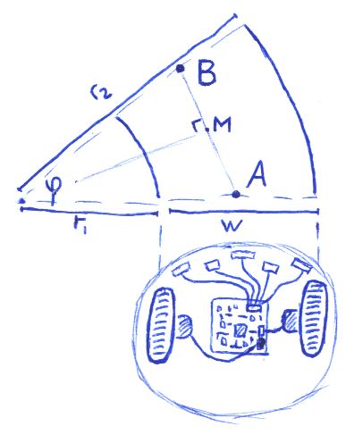
At the beginning of the arc, the robot was at point A (known), at the end it turned out to be at point B (unknown), while the left wheel traveled a known path S 1 = φr 1 , and the right wheel traveled a known path S 2 = φr 2 . The distance w between the tracks is constant, and is determined by the construction of the robot. We get:
r 2 / r 1 = S 2 / S 1 and r 2 = r 1 + w , whence
( r 1 + w ) / r 1 = S 2 / S 1
r 1 S 1 + wS 1 = r 1 S 2
r 1 = wS 1 / ( S 2 - S 1 )
Hence, the angle at which the robot turned, φ = S 1 / r 1 = ( S 2 - S 1 ) / w , and the distance | AB | = 2 | AM | = 2 ( r 1 + w / 2) sin ( φ / 2) = (2 wS 1 / ( S 2 - S 1 ) + w ) sin ( φ / 2) = w · sin ( φ / 2) ( S 2 + S 1 ) / ( S 2 - S 1 )
Here, by and large, and all the mathematics to determine the position: each time we add the calculated φ to the angle of the direction of the robot, and we shift the current coordinates by distance | AB |. The question remains practical: how often to perform such updates of the position? If too often, we will be confronted with the inaccuracy of the wheel sensors measuring the mileage with discrete “ticks”. If it is too rare, then the approximation of a path segment by a circular arc will not be accurate enough.
I decided that the wheel sensor reading is most accurate at the moment of “tick”, so I recalculate the position of the robot for each tick of any wheel - but not more often than the poll time of the robot, recorded somewhere around 80ms; and at least once a second, so that the stopped wheel (for example, when turning) is also recorded. All registered “ticks” are saved to the list, since to recalculate a position I need the mileage of both wheels for the same period of time. We take the gap from the earlier of the previous “ticks” with both wheels, and linearly interpolate the run of the second wheel at the same moment using the “tick list”. For the end of the gap - in the same way, we take the mileage read by the sensor for the “ticked” wheel, and linearly extrapolate the mileage of the second one. Thus, the accuracy should be the maximum achievable.
Every time the position of the robot is recalculated, you need to re-set the wheel speeds in order to direct the robot to its intended target. It is unrealistic to direct the robot exactly to the desired “azimuth”, rotating in place: the said wheel mileage error of ± 7mm turns into an error of several degrees when turning the robot, i.e. the robot will still go "obliquely", and it will have to turn again on the road. Therefore, if the direction to the target is not very different from the current one, I decided to send the robot to the target along an arc, without prior “azimuth guidance”. (If the current direction differs from the desired one by more than π / 2, then such an arc will be greater than the semicircle, which is clearly impractical. In this case, the robot can do nothing but rotate in the right direction.)
To calculate the arc, go back to the drawing above. Now we know the points A and B , and therefore, the angle φ ; you need to find the ratio S 2 / S 1 = r 2 / r 1 : it will set the ratio of wheel speeds, necessary for our arc. Repeat the above calculation in the opposite direction:
| AB | = 2 | AM | = 2 ( r 1 + w / 2) sin ( φ / 2)
r 1 = | AB | / (2sin ( φ / 2)) - w / 2
r 2 = | AB | / (2sin ( φ / 2)) + w / 2
r 2 / r 1 = 1 + w / (| AB | / (2sin ( φ / 2)) - w / 2) = 1 + 2 / (| AB | / ( w · sin ( φ / 2)) - 1 )
How far will such an arc lead us away from the straight line AB ? If a robot needs two meters of free space on its sides to complete the arc, then in our warehouse there is simply no such possibility: the width of the aisles between the shelves is only one and a half meters.

Calculate the distance | MH | between arc and straight: | OH | - | OM | = r - r · cos ( φ / 2) = ( r 1 + w / 2) (1 - cos ( φ / 2))
If the magnitude of this "hump" exceeds the specified limit, then we refuse to move in an arc, and, rotating in place, will try to turn closer towards the target.
As it turned out, in reality, the ratio of the voltages on the motors does not yet determine the ratio of the wheel speeds. It would be possible to select the correct transformation between them, but I solved the problem by “brute force”: I restored the ratio to the 9th degree, i.e. the slightest deviation to one of the sides immediately pushes the robot in the opposite direction. In fact, it was with this exponent that the movement of the robot became truly smooth: with smaller degrees, it deviated very strongly to the side, and returned to the correct route only at the target itself; with large - the correction turned out to be too strong, and the robot was “wound” from side to side by a narrow zigzag.
I conceived to add new functionality to the MarkRobot service from the ReferencePlatform2011 delivery: implement a new portset in the spirit of
First you need something to work with coordinates: it’s not to be stored in
The
(Only now, by copying the code here, I noticed that I had exactly the “double angle formula”, and that instead of shifting to | AB | at an angle of φ / 2, I could move to r 1 + w / 2 at an angle of φ . Well come on.)
Further, the service contains within itself a copy of
In addition to “tick lists”, a position list should be stored in
It remains to supplement the
All that remains in the code of interest is the
This robot drove pretty well, but the problem arose due to accumulating errors. To correct the coordinates, it was enough to read successfully at least 20% of the
Much worse was the case with the error of direction (heading), because we could not correct the direction: the barcode can be read from any angle (and thank God). The accumulated direction error of several degrees is already enough for the robot to go astray and drive in from the full swing into the regiment. A frontal solution would be to install a gyroscope; but there is no ready-made gyro for Eddie, and I would like to avoid the mysteries with a soldering iron and writing firmware.
Correction of direction without a gyroscope and other exotic sensors, I am going to devote the following article.
Prehistory
Last year, we experimented with the Roomba self-propelled vacuum cleaner platform. A new vacuum cleaner cost us around £ 300 (a used one can be found for £ 100 and even cheaper), and it consists of two electric drives for wheels, two touch sensors in front, an infrared sensor at the bottom (for detecting steps) and at the top (for searching for the station) . The exact list of sensors depends on the model: the protocol provides for up to four infrared sensors from the bottom, each of which returns one bit (“the floor is visible / not visible”). In any case, no range finders: all available sensors are one-bit. In addition, there are no “programmable arduins” in Roomba, and in order to control it, you need to install a laptop (or arduin) on top and communicate with the robot via RS-232. Having played enough with a vacuum cleaner, we left it gathering dust on one of the shelves of the warehouse. This year we decided to try Microsoft Robotics Development Studio (MRDS) , to promote which Microsoft formulated the “MRDS Reference Platform” specification - a set of equipment and a control protocol for a “standard” robot. This specification would allow robots to create compatible robots and transfer programs between them. Compared with the hardware of the vacuum cleaner, the Reference Platform is much more complicated and powerful: Kinect is included in the specification, three IR rangefinders and two ultrasonic, and also wheel rotation sensors (encoders). The implementation of the MRDS RP is currently offered only by the company Parallax called Eddie (about £ 1000, not including Kinect). The extraordinary similarity of Eddie with the photos of the prototype robot in the MRDS RP specification suggests that the specification was created in close cooperation with Parallax, in other words, Parallax managed to achieve that Microsoft took their platform as a reference.')
In addition to the variety of sensors, the Eddie has a mechanically impressive platform (declared load capacity of 20kg, and the power of the motors is enough to push the warehouse loader ahead of itself) and the programmable Parallax Propeller controller, i.e. Critical pieces of code can be sewn directly into the robot, and not just command it from a computer.
The British Channel 4 included a two-minute piece with the Eddie demo integrated into a shopping cart in one of the releases of the Gadget Man program. Unfortunately, only the owners of British IP addresses can view the program on Channel 4, and I did not manage to grab it and reload it (maybe someone of the readers will succeed?) - therefore I bring only freeze-frames from there.Task
Just control the robot "forward-back-left-right" - nothing tricky, and the program of such "remote control" is included directly in the delivery of Eddie. But there is no one to steer the loader robots: each of them must himself be aware of where he is at the warehouse, and make his way to the next point. It is with this definition of the position that the main problem arose. GPS-like technologies are swept away: the signal from the satellites does not pass through the roof of the warehouse. Kinect is good at gesture recognition, but how do they recognize storage shelves? On the shelves themselves, unique barcodes every meter are already glued, but first, they are not read reliably “on the move” of the robot and at a distance of 20 cm from the shelves (you cannot get closer - there is a risk of crashing into the support or into a box projecting from the shelf). Secondly, in order to drive up to the shelf at a distance of 20 cm and read the barcode, one already needs to understand the current position - otherwise the robot, which has moved aside from the shelves, loses its orientation completely and irreparably.
The first navigation attempt was based on rangefinders: the robot “gropes” the shelf and travels along it, maintaining a predetermined distance, just as the tottering drinker walks, leaning against the wall through the step. The similarity was really huge: the delay in receiving the signal from the range finders, processing them in the MRDS, forming a command for the motors, and overcoming their inertia - amounted to tenths of a second. During this time, the robot “led away” to the side, so that the “course correction” each time was tens of degrees, and the trajectory was obtained in a wide zigzag. In addition to this, the Eddie rangefinders were not too accurate - the error was up to ± 5 cm - and rather narrowly focused, i.e. the shelves were recognized only on one, in advance of a given height from the floor.Navigation through wheel sensors turned out to be more promising, giving each wheel mileage with an accuracy of about ± 7 mm. Eddie's firmware has already included the calculation of the “robot run” (half the sum of the runs of both wheels) and the “robot directions” (difference between the runs of the wheels, with the normalizing factor), but the current coordinates (x, y) cannot be calculated from only the values of the two counters. It is necessary to break the trajectory of the robot into small simple sections, and summarize the movement in each section. At first glance, I want to bring the path of the robot broken line; but in reality, “at rest” - at a constant speed of the motors - the robot will move along an arc of a circle: the larger the radius, the smaller the difference between the speeds of the motors. On the contrary, the breakpoint, when the robot changes direction, not moving from the place, in reality there is not and can not be. Therefore, we will approximate the trajectory of the robot with a sequence of arcs.
Calculations
It all started with a drawing on a napkin deep at night, when it suddenly dawned on me:
At the beginning of the arc, the robot was at point A (known), at the end it turned out to be at point B (unknown), while the left wheel traveled a known path S 1 = φr 1 , and the right wheel traveled a known path S 2 = φr 2 . The distance w between the tracks is constant, and is determined by the construction of the robot. We get:
r 2 / r 1 = S 2 / S 1 and r 2 = r 1 + w , whence
( r 1 + w ) / r 1 = S 2 / S 1
r 1 S 1 + wS 1 = r 1 S 2
r 1 = wS 1 / ( S 2 - S 1 )
Hence, the angle at which the robot turned, φ = S 1 / r 1 = ( S 2 - S 1 ) / w , and the distance | AB | = 2 | AM | = 2 ( r 1 + w / 2) sin ( φ / 2) = (2 wS 1 / ( S 2 - S 1 ) + w ) sin ( φ / 2) = w · sin ( φ / 2) ( S 2 + S 1 ) / ( S 2 - S 1 )
Here, by and large, and all the mathematics to determine the position: each time we add the calculated φ to the angle of the direction of the robot, and we shift the current coordinates by distance | AB |. The question remains practical: how often to perform such updates of the position? If too often, we will be confronted with the inaccuracy of the wheel sensors measuring the mileage with discrete “ticks”. If it is too rare, then the approximation of a path segment by a circular arc will not be accurate enough.
I decided that the wheel sensor reading is most accurate at the moment of “tick”, so I recalculate the position of the robot for each tick of any wheel - but not more often than the poll time of the robot, recorded somewhere around 80ms; and at least once a second, so that the stopped wheel (for example, when turning) is also recorded. All registered “ticks” are saved to the list, since to recalculate a position I need the mileage of both wheels for the same period of time. We take the gap from the earlier of the previous “ticks” with both wheels, and linearly interpolate the run of the second wheel at the same moment using the “tick list”. For the end of the gap - in the same way, we take the mileage read by the sensor for the “ticked” wheel, and linearly extrapolate the mileage of the second one. Thus, the accuracy should be the maximum achievable.
Every time the position of the robot is recalculated, you need to re-set the wheel speeds in order to direct the robot to its intended target. It is unrealistic to direct the robot exactly to the desired “azimuth”, rotating in place: the said wheel mileage error of ± 7mm turns into an error of several degrees when turning the robot, i.e. the robot will still go "obliquely", and it will have to turn again on the road. Therefore, if the direction to the target is not very different from the current one, I decided to send the robot to the target along an arc, without prior “azimuth guidance”. (If the current direction differs from the desired one by more than π / 2, then such an arc will be greater than the semicircle, which is clearly impractical. In this case, the robot can do nothing but rotate in the right direction.)
To calculate the arc, go back to the drawing above. Now we know the points A and B , and therefore, the angle φ ; you need to find the ratio S 2 / S 1 = r 2 / r 1 : it will set the ratio of wheel speeds, necessary for our arc. Repeat the above calculation in the opposite direction:
| AB | = 2 | AM | = 2 ( r 1 + w / 2) sin ( φ / 2)
r 1 = | AB | / (2sin ( φ / 2)) - w / 2
r 2 = | AB | / (2sin ( φ / 2)) + w / 2
r 2 / r 1 = 1 + w / (| AB | / (2sin ( φ / 2)) - w / 2) = 1 + 2 / (| AB | / ( w · sin ( φ / 2)) - 1 )
How far will such an arc lead us away from the straight line AB ? If a robot needs two meters of free space on its sides to complete the arc, then in our warehouse there is simply no such possibility: the width of the aisles between the shelves is only one and a half meters.
Calculate the distance | MH | between arc and straight: | OH | - | OM | = r - r · cos ( φ / 2) = ( r 1 + w / 2) (1 - cos ( φ / 2))
If the magnitude of this "hump" exceeds the specified limit, then we refuse to move in an arc, and, rotating in place, will try to turn closer towards the target.
As it turned out, in reality, the ratio of the voltages on the motors does not yet determine the ratio of the wheel speeds. It would be possible to select the correct transformation between them, but I solved the problem by “brute force”: I restored the ratio to the 9th degree, i.e. the slightest deviation to one of the sides immediately pushes the robot in the opposite direction. In fact, it was with this exponent that the movement of the robot became truly smooth: with smaller degrees, it deviated very strongly to the side, and returned to the correct route only at the target itself; with large - the correction turned out to be too strong, and the robot was “wound” from side to side by a narrow zigzag.
Implementation
I conceived to add new functionality to the MarkRobot service from the ReferencePlatform2011 delivery: implement a new portset in the spirit of
PositionOperations : PortSet<GetPosition, SetPosition, SetDestination> , and so that the service itself, transparently for the user, polls the wheel sensors and exposes the voltage on the motors. In fact, it did not come to this realization - only a muddy prototype was ready without sharing the responsibilities between the services. I will try, nevertheless, to show that I did it.First you need something to work with coordinates: it’s not to be stored in
System.Drawing.PointF . public struct Position { public readonly double x, y, heading; public Position(double x, double y, double heading) { this.x = x; this.y = y; this.heading = heading; } private static double Sqr(double d) { return d * d; } public double DistanceTo(double x, double y) { return Math.Sqrt(Sqr(this.y - y) + Sqr(this.x - x)); } public static double NormalizeHeading(double heading) { while (heading < -Math.PI) heading += 2 * Math.PI; while (heading > Math.PI) heading -= 2 * Math.PI; return heading; } // turn angle/2, go ahead distance, turn angle/2 again public Position advance(double distance, double angle) { double newHeading = heading + angle / 2, newX = x + distance * Math.Cos(newHeading), newY = y + distance * Math.Sin(newHeading); return new Position(newX, newY, NormalizeHeading(heading + angle)); } } The
advance method implements the recalculation of coordinates by a given angle of rotation φ and the distance covered | AB |, as in the drawing in the middle of the article.(Only now, by copying the code here, I noticed that I had exactly the “double angle formula”, and that instead of shifting to | AB | at an angle of φ / 2, I could move to r 1 + w / 2 at an angle of φ . Well come on.)
Further, the service contains within itself a copy of
PositionKeeping , within which there are two instances of EncoderLog - the “ EncoderLog list”, a separate copy for each wheel. The list is SortedList in SortedList , because (theoretically) sensor data may not arrive in chronological order. The only non-trivial method in EncoderLog is linear approximation of the run to get its value at any time between “ticks” or after the last “tick”. private class PositionKeeping { private static readonly DateTime initialized = DateTime.Now; public class EncoderLog { private SortedList<DateTime, double> log = new SortedList<DateTime, double> { { initialized, 0 } }; public void Register(DateTime at, double reading) { log[at] = reading; } public void Reset(DateTime at, double reading) { log.Clear(); log.Add(at, reading); } public DateTime LastTick { get { return log.Last().Key; } } public double LastReading { get { return log.Last().Value; }} public double ReadingAt(DateTime at) { int index = log.Count - 1; while(index>=0 && log.Keys[index] > at) index--; if(index<0) return double.NaN; // before first reading; impossible // now, log.Keys[index] <= at, and log.Keys[index+1] > at DateTime preceding = log.Keys[index], following = index<log.Count-1 ? log.Keys[index+1] : DateTime.MaxValue; if(following == DateTime.MaxValue) { // last reading precedes at; extrapolate if(index==0) // there's only one reading return log[preceding]; else { DateTime nextPreceding = log.Keys[index-1]; return log[nextPreceding] + (at-nextPreceding).TotalSeconds * (log[preceding]-log[nextPreceding]) / (preceding-nextPreceding).TotalSeconds; } } else // both readings are available; interpolate return log[preceding] + (at-preceding).TotalSeconds * (log[following]-log[preceding]) / (following - preceding).TotalSeconds; } } public EncoderLog leftEnc = new EncoderLog(), rightEnc = new EncoderLog(); In addition to “tick lists”, a position list should be stored in
PositionKeeping at the time of each “tick” - we will measure the distance traveled from this saved position in order to get a new position. private SortedList<DateTime, Position> position = new SortedList<DateTime, Position> { { initialized, new Position(0, 0, Math.PI / 2) } }; public void Register(DateTime at, Position pos) { position.Add(at, pos); } public void Reset(DateTime at, Position pos) { // the position has changed => old ticks logs become obsolete leftEnc.Reset(at, leftEnc.ReadingAt(at)); rightEnc.Reset(at, rightEnc.ReadingAt(at)); position.Clear(); position.Add(at, pos); } public Position Current { get { return position.Last().Value; } } It remains to supplement the
PositionKeeping class by calculating the new position using the data of both wheel sensors - in accordance with the formulas derived. Update can be called from the sensor check cycle ( ServiceHandlerBehavior.Concurrent ), and takes the service port argument, where it sends new coordinates if a tick is registered. This message changes the state of the service, so it should be treated as ServiceHandlerBehavior.Exclusive . private static readonly TimeSpan RegisterDelay = TimeSpan.FromSeconds(1); // register null-tick if no actual ticks for this long public void Update(DateTime at, double left, double right, PositionOperations mainPort) { DateTime prevRef = Min(leftEnc.LastTick, rightEnc.LastTick); SetPosition set = new SetPosition { Timestamp = at, LeftEncUpdated = left != leftEnc.LastReading || at > leftEnc.LastTick + RegisterDelay, LeftEncReading = left, RightEncUpdated = right != rightEnc.LastReading || at > rightEnc.LastTick + RegisterDelay, RightEncReading = right }; if(set.LeftEncUpdated || set.RightEncUpdated) { set.Position = Recalculate(prevRef, left, right); mainPort.Post(set); } } private Position Recalculate(DateTime prevRef, double left, double right) { double sLeft = left - leftEnc.ReadingAt(prevRef), sRight = right - rightEnc.ReadingAt(prevRef); Position refPos = position[prevRef]; // has to exist if the encoder reference exists if (Math.Abs(sRight - sLeft) < .5) // less then half-tick difference: go straight return refPos.advance(Constants.CmPerTick * (sRight + sLeft) / 2, 0); else { double angle = Constants.CmPerTick * (sRight - sLeft) / Constants.WheelsDist, distance = Constants.WheelsDist * Math.Sin(angle / 2) * (sRight + sLeft) / (sRight - sLeft); return refPos.advance(distance, angle); } } } All that remains in the code of interest is the
SetPosition handler, which sets the voltage on the motors so that the robot moves toward the target. [ServiceHandler(ServiceHandlerBehavior.Exclusive)] public void SetPositionHandler(SetPosition set) { if (!set.LeftEncUpdated && !set.RightEncUpdated) { // position updated by an absolute reference. positionKeeping.Reset(set.Timestamp, set.Position); } else { if (set.LeftEncUpdated) positionKeeping.leftEnc.Register(set.Timestamp, set.LeftEncReading); if (set.RightEncUpdated) positionKeeping.rightEnc.Register(set.Timestamp, set.RightEncReading); positionKeeping.Register(set.Timestamp, set.Position); } // the navigator Destination dest = state.dest; double distance = set.Position.DistanceTo(dest.x, dest.y); if (distance < 5) // reached { drivePort.SetDrivePower(0, 0); SendNotification(submgrPort, new DriveDistance()); return; } double heading = Position.NormalizeHeading(Math.Atan2(dest.y - set.Position.y, dest.x - set.Position.x)), power = (distance < 50) ? .2 : .4; // a few magic numbers if (Math.Abs(heading) < .05) { // straight ahead drivePort.SetDrivePower(power, power); return; } double r = distance / (2 * Math.Sin(heading / 2)), hump = r * (1 - Math.Cos(heading / 2)); if (Math.Abs(heading) > Math.PI / 2 || Math.Abs(hump) > Constants.MaxHump) { // not reachable by an arc; rotate if (heading > 0) // rotate left drivePort.SetDrivePower(-.3, .3); else // rotate right drivePort.SetDrivePower(.3, -.3); } else { // go in arc double rLeft = Math.Abs(r - Constants.WheelsDist / 2), rRight = Math.Abs(r + Constants.WheelsDist / 2), rMax = Math.Max(rLeft, rRight); // <Patrician|Away> what does your robot do, sam // <bovril> it collects data about the surrounding environment, then discards it and drives into walls drivePort.SetDrivePower(power * Math.Pow(rLeft / rMax, 9), power * Math.Pow(rRight / rMax, 9)); } } What's next?
This robot drove pretty well, but the problem arose due to accumulating errors. To correct the coordinates, it was enough to read successfully at least 20% of the
SetPosition , and “restart” PositionKeeping calling SetPosition with LeftEncUpdated = RightEncUpdated = false . For a few meters between the readable barcodes, the error in determining the coordinates did not exceed 20 cm - just as much we left in reserve between the robot and the shelves.Much worse was the case with the error of direction (heading), because we could not correct the direction: the barcode can be read from any angle (and thank God). The accumulated direction error of several degrees is already enough for the robot to go astray and drive in from the full swing into the regiment. A frontal solution would be to install a gyroscope; but there is no ready-made gyro for Eddie, and I would like to avoid the mysteries with a soldering iron and writing firmware.
Correction of direction without a gyroscope and other exotic sensors, I am going to devote the following article.
Source: https://habr.com/ru/post/161803/
All Articles