From home automation and smart homes in general to a specific example.
Recently, a lot has been written about home automation and smart homes. I would like to share my experience, general considerations and a specific project. This article will be useful for those who simply would like to know what a smart home can be useful or convenient for, as well as those who would like to control (or just watch) from any device with a browser (phone, tablet, reader, HTPC, laptop, desktop). computer, etc.) home automation system. And it can be done from anywhere in the world. My experience and example described in the second part of this article (Arduino, jQuery Mobile Web interface, etc.) can be useful to those who already have some kind of home automation system (for example X10) or those who start this thorny path.
The main reason why home automation systems have not yet become so popular is the emphasis on lighting, which is usually done when they are promoted. After all, blinking light (like LEDs on Arduin) without getting up from the couch is a self-indulgence that has no practical significance and pushes people away from serious thoughts about introducing and using home automation systems in their homes and apartments. Flashing light (what is usually sharpened 90% of the functional) no one needs but for example, it is convenient to control the heating individually in each room and saves energy = money. The exorbitant prices for the components themselves (cheap at cost) of ready-made selling home automation systems, together with the prices for integrating them, only add fuel to the fire. I hasten to assure you that the most expensive component will be the $ 20 Arduino Meg. If we consider the issue as a whole, then I see only the following list of tasks that makes practical sense to centrally automate:
> climate control temperature (heating / air conditioning) and humidity (humidifier / dryer),
> daylight control (blinds, shutters, awnings)
> and management of watering lawns, flower beds and lawns around the house (if any, and they still need to be watered).
From decentralized systems, it is convenient to have a local (without a central control of 1-2 sensors that control directly turning on the backlight) low-power LED backlight of the stairs (sometimes the floor) and parts of the tables in the kitchen that are shaded from conventional ceiling lighting by cabinets and shelves. The same light, in combination with the above, is irreplaceable at night when necessary, without waking anyone and yourself in the first place, to get into the kitchen (and cut off something from something and eat without sharing it with anyone) or in another institution without stumbling about prudently scattered toys. It also makes sense to include motion sensors with main lighting ONLY in technical rooms: cabinets, storage rooms, garage, laundry rooms and so on. Motion sensors and centralized systems are not practical to use for basic lighting in residential areas. External and decorative festive lighting at home is most conveniently switched on from ready-made penny blocks with light sensors and / or timers. Real security systems connected to response services (not just sensors scattered around the house and webcams) usually do not make sense to mix with smart home systems for many reasons.
So let's start with the most current. The ideal object is heating which can be controlled for example: electric (batteries on wheels in a socket and wall batteries) and centralized or not so much heating of a private house. In my example, we will consider working with the Thermo Pump system (Heat Pump in North America) with fuel oil heating by means of a direct connection to the existing Control Unit (thermostat) and additionally devices. In the first version of the system I used X10 protocol devices and sockets. But unfortunately, they didn’t work well, because of the slow interface and very loud switch-overs that woke up all the households. Later I switched the system to a radio outlet, which turned out to be much simpler and quieter than x10. These sockets are available in a huge range of radio frequencies and voltages. All this is applicable to a huge variety of other systems. It all started with the fact that my friend along with his neighbor gently dropped on my head about the huge role of the miracle of the wonderful - Arduino in modern society and that I, as a person who know and love to hold a soldering iron, simply have to get this Arduino mania as soon as possible. I swayed in every possible way and said that the area of practical (not robot-toys) use of her house is very doubtful and, based on a powerful microcontroller, consistently lit up the LED bars to illuminate the steps of the stairs (instead of a single shift register and generator) is just a gun on sparrows and the rest is pampering . But still, they managed to lay the Arduino grain in my head and like all grains with the arrival of spring and on the approaches of summer the sprout began to make its way. I do not like hobby projects for the sake of the projects themselves. Some practical side should be present and all the more so that the resource ($ and time) capacious projects for a family person must also have a high WAF (Wife acceptance factor) or, as my Dad says, it is easy to legalize it.
')
And as always, laziness was the engine of progress. We sat a little after noon on the veranda, the sun was pleasantly hot, and at the same time a son slept in a bedroom on the top floor and judging by the Chinese thermometer for $ 2 (to which it was necessary to walk still and look without waking my son)
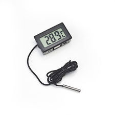 the temperature was over 26. So you should now go into the living room and turn on the central air conditioner, and then turn it off again so that it does not turn on every time the temperature rises a little. It is especially unpleasant to do in the summer at night, having frozen under a light blanket, it is necessary to jump up and again without waking up all the households to run to the living room to the console and cut down this achievement of the last century. Then I realized that it was time to stop such a disgrace and call a friend with the words "Where is your praised Ardunya, Give it here right now we will look at what it can do!". I’ll say right away that I didn’t choose it at all and didn’t think that it would turn out to be so worthless (for example, when working with strings), and even from anger and powerlessness to fight it, I almost moved into the middle of the project on STM32. In the end, still remained with her, but first things first.
To make it easier to understand why everything is done the way it is and how you spread my experience and best practices on bread, let's start by describing what I have / had at my fingertips:
1) Private house in Canada (I would like to say that it is mine, but of course it belongs to the bank and no matter how absurd it may sound but to have it fully paid at current rates is not even profitable) built in 1959 as they are called Split Level those house two floors, but half of it is shifted vertically relative to the other half to the floor of the floor.
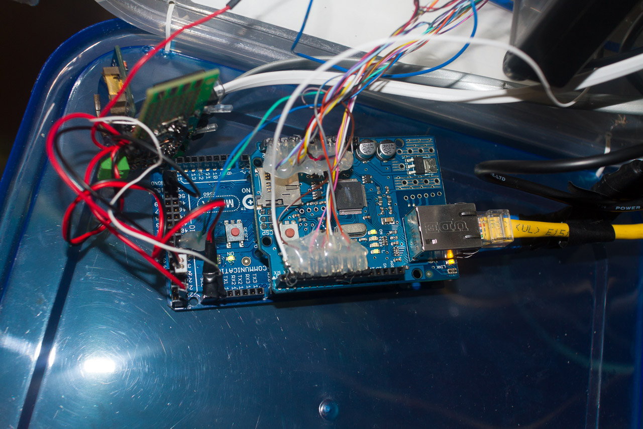
2) Arduino Uno (later, because of the small number of I / O for X10 and radio, Mega was needed)
3) Dear and Native Ethernet Shild. Something I did not manage to launch and find an adequate library for ENC28J60
4) Desire, time and some money.
As is customary here, the bedrooms are on the top floor and for me it turns out to be on the floor of the floor above the living room where the ominous control panel of the heating heating system is bolted to the wall. Here such systems are called HVAC (heating, ventilation, and air conditioning) but in reality this is a usual huge (tens of thousands of BTUs or they measure them here in tons) which is split an air conditioner external heat exchanger and whose compressor is located outdoors and the heat exchanger is built in The central ventilation system, which draws half a kilo of a cotton blower fan from the living room floor, drives it through two heat exchangers (one to the air conditioner and the other from a fuel oil or gas burner) and drives them into each room through the duct system. The convenience and the name of the heat pump itself is due to the fact that this unit can drive freon in both directions and, accordingly, not only cool but also heat the air in the house. It should be noted that it can be heated more or less effectively only if it is warm enough outside more than 0 or -5 (depending on the model and design). If it is cold, then the heat pump will not work and for this purpose just need a tank with fuel oil or gas.
I started my project and ambitions with small, so let's and we will understand how this HVAC is made and how to manage it. In fact, the devil is not so bad. One of the conveniences is the liquid standardization of everything domestic and not so much in America that allows you to cross hedgehogs with snakes using an open, simple (sometimes too) and well-known (usually ancient, well-developed) protocol / standard. In our case, the system itself (fan burners, heat exchangers, you can buy one manufacturer's air conditioner second, a humidifier from a third and a Control Unit for all this from a fourth. Honestly, I don’t know whether similar devices are called / controlled in Europe, but I think that everything is either lapped up or very similar As far as I understand, such systems already exist in Russia and carry them from anywhere / cheaper, so you have great chances to encounter such a system. Let's look at the diagram of a typical system connection before we start it bump into the system.
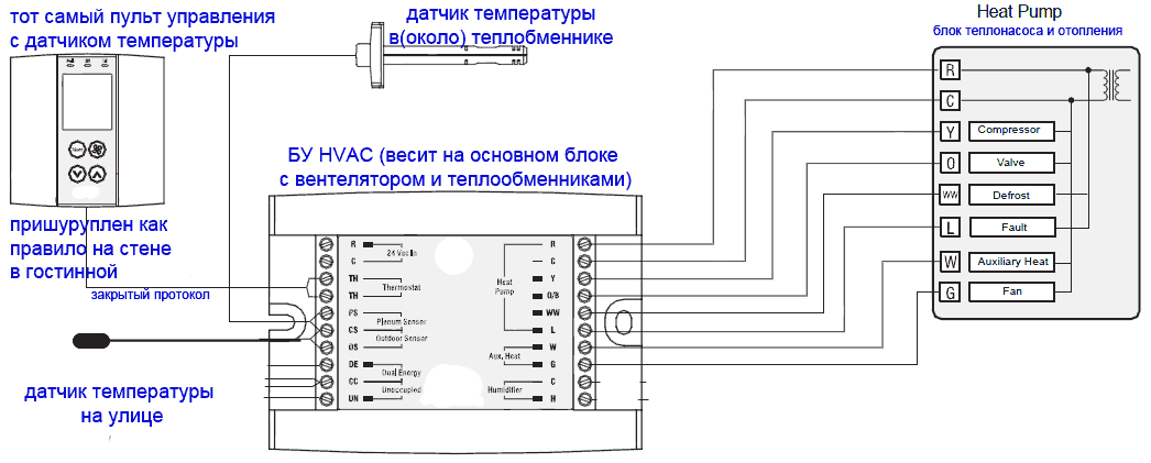
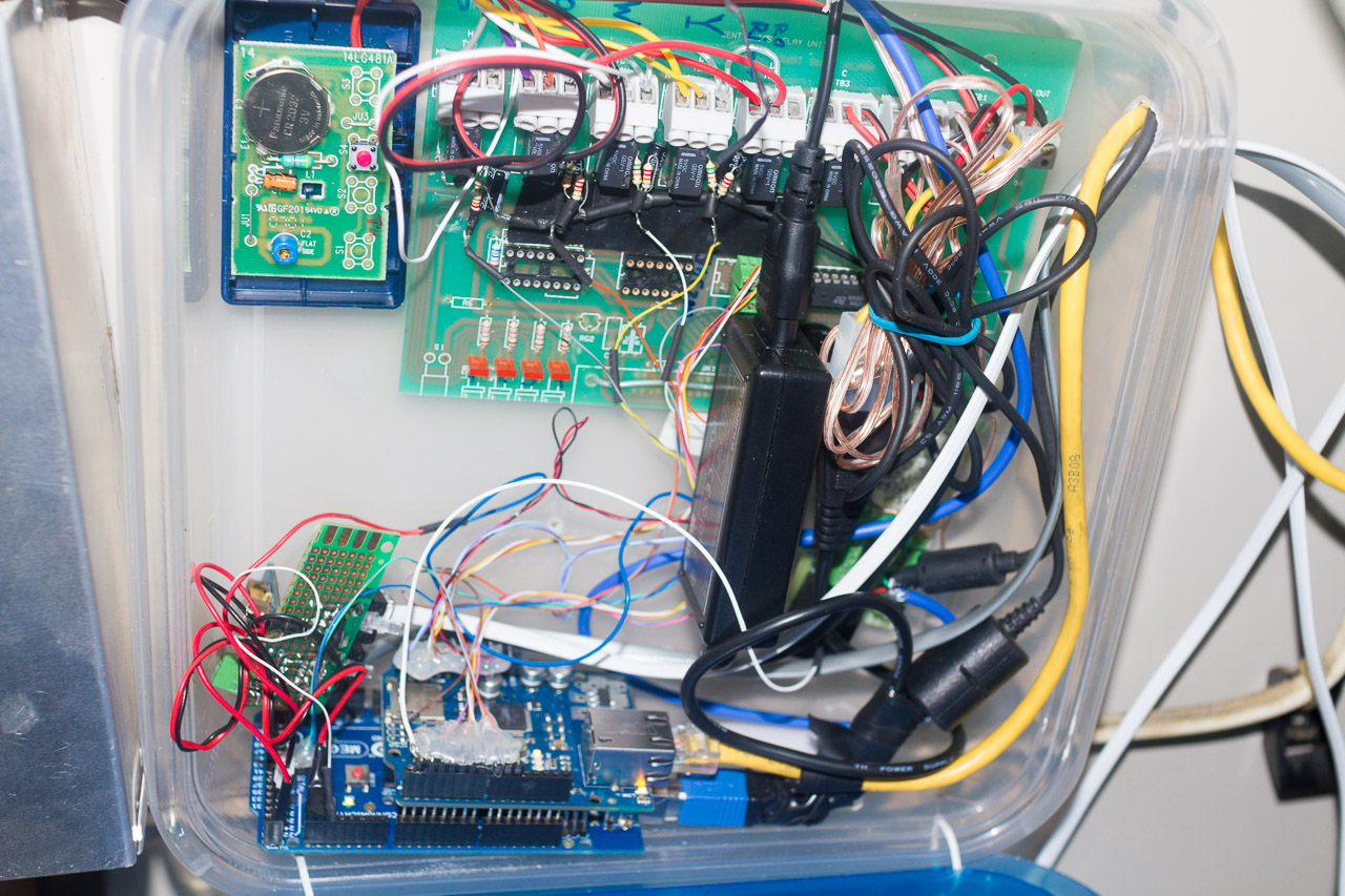
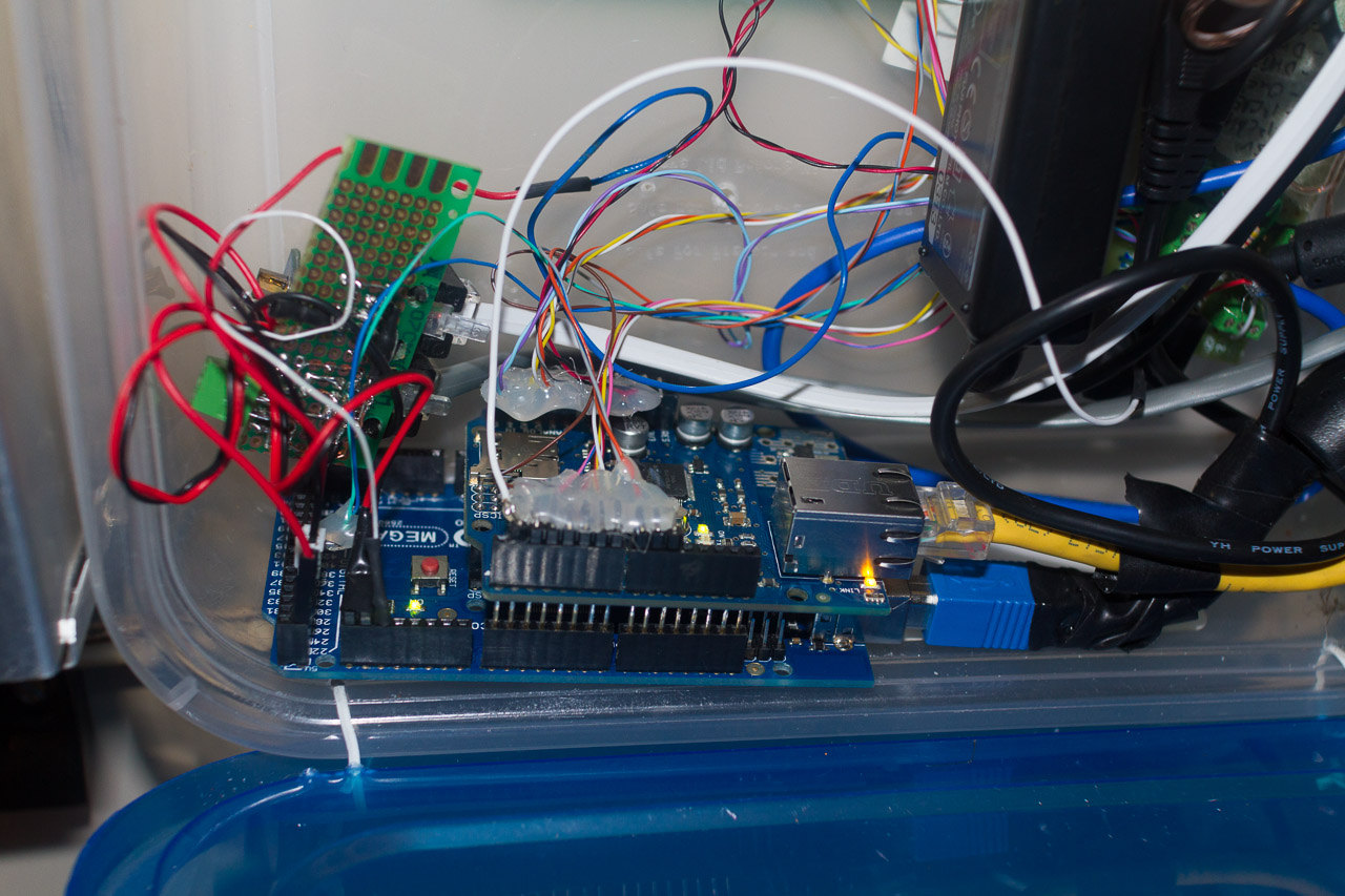
As we see almost everything is clear at first glance. The only thing that needs to be explained is that the control unit is powered and the heat itself is controlled by variable 24 volts. which are fed from the input transformer R and C. Line C is common and always connected. Accordingly, when applying R (closure) to Y, O, W, or G turns on respectively. block. From this we will make a start. So if they include something the worse we are? We will do so that our new system will complement the existing one. Those controls can be exercised from the old console and controller as before, but only when necessary, the Arduino can disconnect the old system from the control and take the furrows in their hands and then give them back. Let's set the relyushki.

And we put them so that without power and disconnected in general, they retain the same design. R-0 disables the standard control module and transfers control to our Arduin. R-1-4 supply the desired voltage to the appropriate line. This control voltage R is applied to each relay with a green wire. It is nice to manage, of course, but the system is serious and if we accidentally or not very well turn it on or in the wrong combination. For example, the heat exchanger will warm up and the fan will not drive the air and remove heat from it, it can overheat and cause a fire, but this is not why we. In order to avoid similar situations let's make triple protection. And so the first bastion will be the voltage sensors on each line S1-4 (they should be 4p).
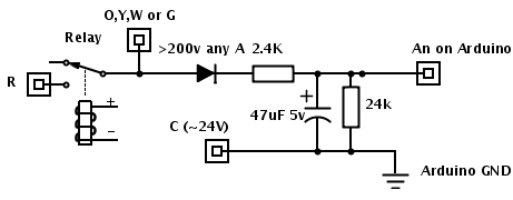
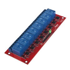
They are a diode two resistors (divider) and a small electrolyte. This can be a mounted assembly as in the photo. As a result, we can know in Arduin whether there really is a voltage on each of the control lines or not. The corresponding if the current state of the control lines (Y, O, W, G) does not correspond to what we should display the error code and turn off the system. The next bastion is our additional temperature sensor in the heat exchanger chamber (plenum sensor). If there is too hot or cold (close to 0C), then we again output the code and turn off the system. It is obvious that it is impossible to power the relays directly from the outputs of the Arduin, therefore, one must either pile up the transistor to each relay or buy a ready-made module with several relays and transistors on one board. I buy 99% of the components in ibei. For example, ibee is full of such 8 channel modules (8 Channel Electronic Relay Module) of about $ 9. or you can buy 4 + 2 (since in fact we only need 5 and one spare)
I used Chinese digital DHT22 as temperature and humidity sensors.
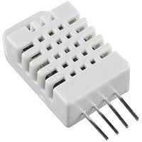 which are well established. They need only three wires +5, GNd and Data. Wires can be quite long without loss of accuracy and signal. One sensor is thrown out into the street in the shade and under a canopy from direct ingress of moisture. One sensor in the house.
 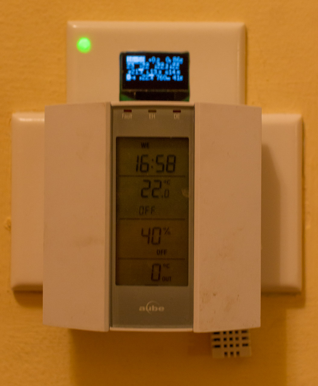 In the house that was built many years ago, the biggest problem is usually to hold new wires, so I tried to use the current wiring to the maximum. For DHT22 there are several libraries. I had problems with everyone except this one . I put the internal DHT22 next to the wall mounted control panel. If in your house as in my once there was an HVAC control system, then you should have as much as 6-core cable going from the control unit to the place where the remote control with the indicator and buttons hangs. Modern consoles (like mine) require only 2 wires. Thus, we have at our disposal 4 wires already laid. In them we run + 5V, GND, Data for the internal DHT22 and the last Serial (UART) Tx from Arduina to display information on the display.
As a display, I used a small (2.5 cm) OLED screen with a serial interface .
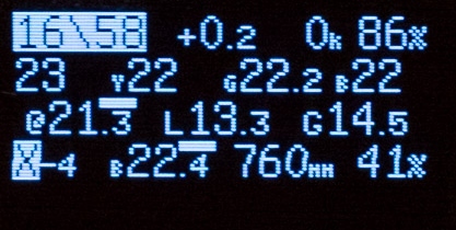 YES, it is a little expensive, but there are several unique differences from similar ones: The presence of a Serial (UART) interface, which allows using only one wire to connect it, the presence of five digital outputs on the screen controller (where we connect the RGB LED for an additional display of the system status) and finally, compactness combined with contrast and excellent readability both in bright light and at night, and it does not illuminate the entire corridor at night like any LCD with the backlight always on.
Then there was the problem of how to place temperature sensors in each room, without additional wires, power and radio modules. As a sensor, I chose a digital DS18B20,
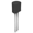 (with good accuracy + - 0.5C) which needs only two wires (ground and signal). You can hang them up a lot on these 2 wires in parallel (each has its own unique MAC address). But even to stretch two wires in all rooms is hellish work. It dawned on me. After all, a telephone cable is laid in all the rooms and it is 4-core and, at best, 2 wires are used for the telephone (usually red and green) and the rest (yellow and black) pass through all the places I need and remain free. Thus, without cutting the wires but only exposing the required two, I soldered to them in each room on DS18B20.
  The total length of the wires turned out to be quite large and if the signal wire was propped up (by + 5V) with recommended 4.7 kOhm, then in my case the sensors were practically not readable and I reduced the prop resistance by half to 2.3 kOhm and everything worked perfectly.
Then I got confused by the pressure sensor and stopped at the cheap BMP085
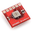 but it has an I2C interface, which again saves legs and the number of wires. Since he can still read the temperature of his I put in the basement, where it was closer and easiest to pull the new wires (already 4). I tried to make maximum use of standard telephone cables and connectors (RJ11) so that the design could be disassembled and repaired - replacing the suitable one.
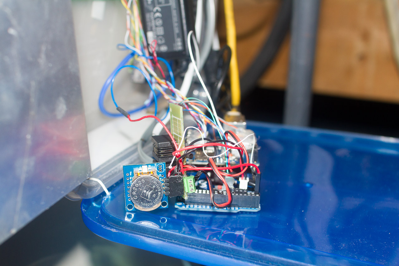
  When you connect this barometer on the same I2C bus as the RTC (module of non-volatile clocks) there are not very clear problems. They interfered with each other and until I put a small delay before reading the barometer everything was not working stably. Since short temporary power outage is not such a rarity and the RTC module
  worth a penny I added it for non-volatile time. Mostly needed when using x10. Using it, there was a desire to automatically synchronize it with NTP via the Internet (since we already have it), but something did not work out for me to cross the webduino server and NTP. As a result, the NTP time (Unix epoch) is sent to the Arduino (and the RTC is updated) every time when any settings or modes are changed in the web interface. That has its drawbacks as it takes javascript from the time on the current computer or mobile device and is not always accurate and in the correct time zone.
I send the commands of my Arduin radio rosettes on the air with a penny ($ 2) transmitter
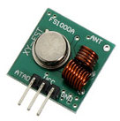 module. Their dime a dozen on ibey (search "RF transmitter 315 Mhz ..") and in any store. The only thing you need to choose the right radio frequency corresponding to your sockets. Unfortunately, my sockets are not correctly supported by the standard RCswitch library. In the description of the library there is a list of supported chips , but you should not be upset if your is not on the list, it worked for me after analyzing the ether manually and without a library. About the similarities, work with the library is much written. In particular, here: http://habrahabr.ru/post/213425 http://habrahabr.ru/post/212215 I used 110V sockets
  . Despite the fact that radio control requires a non-standard solution, it is the simplest and most budgetary solution to the task at hand. Namely, turn on and off electric batteries or any other device (not necessarily resistive) by time or manually, and sometimes turn on and off the outside light. Insteon, Zwave, and others have many sometimes unnecessary additional functions but are much more expensive and have problems with the openness of the interface so that Arduino can send simple commands to the devices. The only problem with the x10, Insteon and other outlets is that they click very loudly during the switchover. This is especially annoying quiet at night. Another caveat: x10 was sharpened and popular in North America and, accordingly, under 110 volts. Here everyone chooses for himself. Or pay a lot for:
Z-Wave - there are no ready sockets, there are strangely shaped relay modules that also click on quieterly and they need to be hidden somewhere in the walls, then immured, it is not clear how to maintain them - change / repair them. But there were USB modules for sending commands. But for this, you also need a microcomputer (maybe a router is suitable) with the correct OS drivers, etc.;
Insteon - there are sockets, but it also nasty clicks like x10 and as far as I understand there is no open module for sending commands and the system is also sharpened for 110V;
It’s up to you to bother with integration and sending commands to this network or pay 5-10 times less for each radio device and, if necessary, undermine the code for it. Like any other thing, everything for 110V is cheaper. Of course, there are more extreme ways, such as the idea described by several authors here, the idea of entangling the whole apartment (house) with a pair (and in fact a bundle) of hammer wires and collecting each control and controlled device from scratch to manually use the 1-Wire protocol. Some went even further and developed their own protocols ...
I also, like a kiter, fastened an anemometer (wind speed sensor). For its measurement, I used a cup sensor with hands and a reed switch closing 1 kΩ between two contacts during rotation of the cups.
 The program uses an interrupt and the number of times + 5V is measured (the transition from 0 to 1) to the digital input (jumped by 5 kOhm on the same + 5V). This value is multiplied by the factor suitable for your sensor and from the number of closures in one second the wind speed in knots is obtained. Also, for each hour, the maximum and minimum values of speed (gusts) are measured and the maximum per hour is displayed. The current and maximum values are sent to the web. Each sensor must be calibrated individually and select the correct factor. To control the garage door, I used a spare radio remote control from it and with the help of an additional relay (sixth) I emulated pressing a button on the remote (opening the remote and soldering buttons to the contacts).
The communication protocol of the standard CU thermopomp with its remote control (usually 2 wires) is usually closed and our arduin cannot know which mode and settings are set in the standard control unit, but with the help of our sensors we can know what mode is HVAC now and although they also have There is a temperature sensor in the heat exchanger; additional protection with the help of Arduine will not interfere. People often ask me: Is it not terrible for me to trust Arduine to manage such a responsible system with my house? My code is open and transparent. I understand what is happening and I can always catch and correct the inaccuracy (if such remained after six months of using the system). And most importantly, I can add any features that I need. In the same box, the less powerful controller is most likely and of course there is nothing to change and add.Without arduine, adding again limited functions like access from the Internet to a standard CU costs a new box of hundreds of dollars. It all startedNot from what I wanted to save, but I needed convenient functions for me that could not be bought from equipment manufacturers for any money. But of course, if you take into account the price of man hours spent by me, and even by you, if you just decide to do this on the basis of my and other developments, this project is certainly cheaper to buy ready-made but say goodbye to flexibility and necessary functions. This is about how to put FreeBSD and painstakingly long and for every reason to dig into the flea market knowledge of the Internet and manually from the command line to twist it for themselves in comparison Mac OS, beautiful finished but limited based on the same BSD. The main one is the inclusion of heating / cooling to the desired temperature is not forever or according to the schedule but only for an hour of 2-4. It sounds simple and convenient, but not present in the standard CU.
If you want to control only a thermopump without RF, RTC, barometer and other memory problems, Uno has enough legs (I did in the first phase of my project). In the full version, the Mega is indispensable. Let's look at the resulting functions and interface.
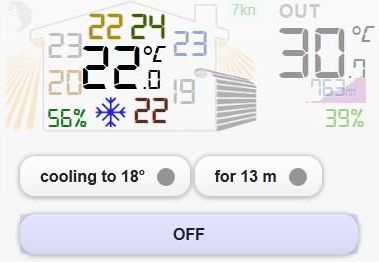
The interface itself is made within the framework of just one html page using Ajax technology for data exchange with the Arduino web server (webduino) and is based on the JQuery Mobile libraries. Therefore, to work, you need several image files and the libraries themselves, which can be replaced by links.
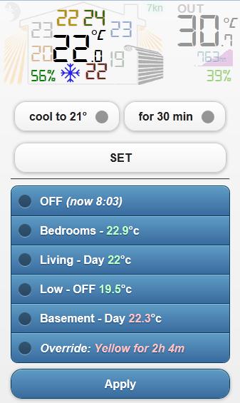
In the upper left corner, we see the moon, which means that according to the settings of the day and night (in the first line of the blue block) is now the night mode. If daytime mode there will be sunshine. Next we see our house. In the house there are a lot of temperatures in each room and in the center the temperature is tenth, this is the temperature in the living room on the main level. Green below the house we see the relative humidity inside the house. A snowflake to her right is an indicator that the air conditioner is working now. At this point, different icons are displayed with different modes of operation (heating with a thermopomp or AUX or x10). If the icon is muted (translucent), then the system is in this mode but not active. Those.for example, in conditioning mode to a temperature of 21 degrees, but since now 20 degrees the air conditioner is not active. If two modes work at the same time, for example, heating x10 and heating thermopump, two icons will flash in sequence. On the left and right of the house we see the rays, when clicked, they become bright and when pressed again, they are muffled again. This is the inclusion of external lighting at home. I have an outside light in the backyard and in front of the house. The control is transmitted by x10 and the numbers of the corresponding devices are registered in the html (JS) code, Arduina only sends commands to the device numbers transferred from the HTML. To the right of the house we see an automatic garage door. which opens and closes when you click on it.From above, to the right of the house, we see the current (averaged over 1-2 minutes) or maximum wind speed in knots per hour. The value of wind speed is highlighted in different colors from blue to red depending on the speed and in accordance with the internationally accepted colors of the Beaufort scale. Top right, we see the temperature outside and below the current atmospheric pressure. The pink background for the pressure value is the graph of its relative change over the past 24 hours (x-time, y is the relative pressure value). Under pressure green relative humidity on the street.The pink background for the pressure value is the graph of its relative change over the past 24 hours (x-time, y is the relative pressure value). Under pressure green relative humidity on the street.The pink background for the pressure value is the graph of its relative change over the past 24 hours (x-time, y is the relative pressure value). Under pressure green relative humidity on the street.
Now consider the group of white selects and the SET button. The left temperature selects the desired temperature / mode. Right for how long to enable this mode. If the mode is active then the inscriptions will change a little, as in this example.

If the heating mode is active, then in addition the button will be tinted red and if the cooling is blue. To turn off, you need to leave the temperature and the selected mode on the left and the remaining minutes on the right, and then the SET button will change to OFF and pressing it will turn off the mode. Cooling or heating mode is automatically selected depending on the temperature outside. If the street is less than the value of the constant heat_temp described in the html (JS) file, then only heating will be offered, otherwise only cooling.
Now let's look at the blue x10 block. Clicking on the first line opens the general settings: ON - All Sockets Always On (for example in summer), OFF all sockets always off (for example if you are on vacation), Split - individual settings for groups and rooms take effect. Then you can choose from what hour the day starts and from what night.
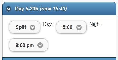 To save the settings, do not forget to click the Apply button below. Further, each row reflects a group of rooms which may consist of one or more rooms. I did the grouping by the floors in my house. On some floors there is only one room and on some more. Each group can be set to ON - all sockets of this group are always on, OFF all sockets of this group are always off (for example, you need to turn on the vacuum cleaner and if the battery will work at the same time it will blow out the fuse), Split (available only for groups with more than one room) - individual settings of the rooms within the group come into force, Day - maintain the specified temperature only during the day (always off at night), Day & Night - maintain the specified temperature for the day and other temperature at night.Each room is accessible to all of the above with the exception of Split. For the changes to take effect, do not forget to click Apply below.
The very last line is the Override mode setting. This mode was made to force the inclusion of sockets in the selected room or lamp for some time. For example, you need to heat the room as much as possible for a certain period in order for the child to have a massage there and continue to maintain the usual temperature in it after an hour. Or turn on the light on the street for half an hour. On the left you select the room on the right for how much to turn on the mode and press the Overrride button. If you need to prematurely disable the mode on the right, select OFF and press Override. All information is updated every upd_interval (constant from html file) seconds. Default = 60 seconds. When the information is updated, the entire upper part of the page with the house blinks.
I would also like to talk about the concept of combining outlets (pool). Suppose you have one big room to heat that in a -5 overboard one battery is not able or it will heat up sooo long. You can put a second RF socket with the same code / address and plug the second battery into it, and both of them will always turn on. That at a relatively warm temperature will lead to frequent clicks and turn on and off these two or more batteries. There is another option: you combine these batteries in the pool in the code of the arduin x10pools [17] = {0,0,0,0,0,1,0,0,13,0,0,0,0,0,0,0 , 0}. Zero means no pool at the given socket address number means the address of the child socket of the pool.A child is turned on if it is colder on the street than the poolt (constant from the html file) or the gap between the desired temperature in the room and the current one is greater than delta_temp * poolf (constants from the html file). I would like to say more about delta_temp (a constant from the html file) that is Delta temperature. It is necessary in order that the modes often do not turn on do not turn off as the sensor readings can jump a little + -. The heating is turned on if the current temperature is less than (the desired one is delta_temp) and it is turned off if it is greater (the desired temperature + delta_temp). The default is 0.5 Grad C.The heating is turned on if the current temperature is less than (the desired one is delta_temp) and it is turned off if it is greater (the desired temperature + delta_temp). The default is 0.5 Grad C.The heating is turned on if the current temperature is less than (the desired one is delta_temp) and it is turned off if it is greater (the desired temperature + delta_temp). The default is 0.5 Grad C.
Now consider the issue of security. Of course, you cannot leave the management of your home accessible to everyone. Since our system consists of a client (JS Ajax html page) and a server (Arduino) you can organize various levels of security. For example, you can put an HTML page on your computer, phone, tablet, etc. (without putting it on a public hosting) and then only you (from devices with this file) will be able to open this control panel with your home systems. The Arduino web server weighs on the internal IP and therefore if you don’t download it on the router to the outside world, then you can only get to Arduin from your internal network. Access to the HTML page itself can be password-protected on the Web server where you want to post it. It is also fashionable to raise the HTTPS server in relation to it.The simplest and in my opinion sufficiently reliable is the public hosting of the page, but the page itself is not connected at start up if it does not pass the parameter to the address of the Arduino server (previously configured by Dinamic DNS and Port Foewarding). It looks like this in the browser is introduced such a link http://myhosting.com/index.html?http://myhome.slyip.net:8081/hvac. If an attacker accidentally stumbles upon your client page, he will not be able to do anything with it without knowing the address of the Arduino server. This is the easiest and most convenient compromise that I use now. Yes, I also have this whole design with a miserable (slow non-supporting HTTPS, etc.) Arduino Web Shield server, in addition to which you still need to host the client page from the icon somewhere else NOT like it.And as soon as I get from China the famous TP-LINK TL-WR703N
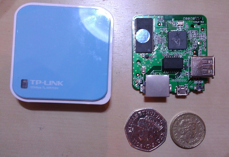 A router that in the blink of an eye turns into a wifi bridged web server with a Serial (UART) interface to the Arduine, I will immediately bolt it to the ardine (or her) and throw out the shield and wipe the wire. Thus, it will turn out even more than what I wanted so unsuccessfully to get from the STM32 controller, namely that everything was in one device (not a separate client page and a separate executive server) and a normal web server on which you can implement a decent degree of convenience of speed and security. B lastly an example of an interface source for Arduin checked on 1.0.1, my library package and HTML GUI .
Source: https://habr.com/ru/post/161359/
All Articles