Self-made external antenna for CDMA2000 / EVDO standard (Intertelecom, PeopleNet operators)
Entry and theory under the cut. Read carefully before asking questions and / or accusing me of incompetence.
There was a lot of information on the Internet about self-made external antennas for 3g modems, but I didn’t find anything to travel, so I’m writing these lines. Very touched by people who believe that 3g is such a communication standard such as GSM, but in fact it is just a generation. These same people are looking for antenna drawings for a 3g modem ... So these drawings are not there, or rather they are, but this is the same thing as coming to the car market and persistently demanding a carburetor for a passenger car without even specifying its model. So we will design the antenna for the CDMA2000 standard, whose operating frequencies lie within 821-894 MHz (and not 800 MHz as many people think). The antenna considered here is not suitable for operators MTS Connect, Utel (Kyivstar). Of course, I met the proposals to catch the signal on the “carnation” (it's a quarter-wave vibrator), to make a canned antenna (that's just the catch, according to calculations, not the bank, but the whole bucket is needed), the notorious Kharchenko antennas (a good option when the signal is there is still, but gain leaves much to be desired), etc.
I stopped at the antenna type "Wave Channel", it is Uda-Yagi. The advantages are high gain, low windage, narrowly directed DND, but the disadvantage is extremely significant - very high precision manufacturing is required. The manufactured director will not become a reflector in size, and the active vibrator will not resonate at the frequency we need. The more accurately you do everything, the better the result will be.
The base station is only 3 km from my house, but the windows are facing the other side of the tower and the signal leaves much to be desired. At first I wanted to make an antenna with 8 directors, but it turned out that we need super-precision here because the departure by 1 mm instead of amplification will give attenuation. A 3-directional antenna does not require such precision manufacturing, but has insufficient gain. Therefore, I stopped at the 5-directional wave channel, considering it to be the “golden mean”. The receiving and transmitting channels are quite strongly separated from each other, because the antenna was calculated in the middle of the receiving channel, that is, at 881 MHz. At first, I wanted to design the antenna in the middle of the band as a whole (859 MHz), but since the Yagi is a narrow-band antenna, we will get a peak of the gain in the non-working range and a smaller gain at the operating frequencies.
')
For the design used the program Yagi calculator .

What we need:
- an aluminum square profile with a cross section of 10 mm (bought by me at the epicenter), not aluminum, will fit, but still it is lighter, but does not affect the characteristics of the antenna;
- an aluminum rod with a diameter of 5 mm and a length of 1 meter (another material will fit, including copper, which is even better, but aluminum is the best price / quality ratio);
- a copper tube with a diameter of 6 mm and a half-meter (the outer diameter is indicated, the wall thickness does not matter);
- bolts with a diameter of 3 mm 7 pcs .;
- cable impedance 50 Ohm;
- Adapters, connectors - all individually for each modem, as they say "Google to help."
Separately about the cable. You will not fit a television cable because of its resistance to 75 ohms. More precisely, it can be attached, but due to inconsistency, the loss in the cable is more likely to be greater than the antenna gain. I took 10 meters of the RG58 cable, it is quite cheap, but the loss is 0.6 dB per 1 meter of cable, i.e. I personally lost 6 dB despite the fact that the difference in the signal with and without the antenna is 20 dB. Because saving on the cable is not worth it.
From the tools:
- saw for metal;
- drill;
- tap on the top three;
- drill 2.5; five; 6;
- flat file;
- a caliper (in the extreme case, the ruler will come down);
- arms.
First the drawings:
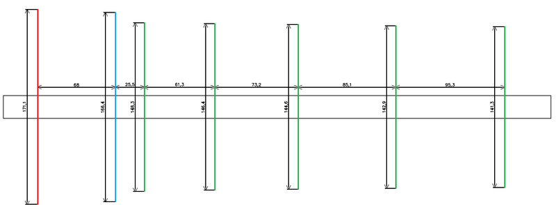
Red is the reflector, blue is the active vibrator, green is the directors.
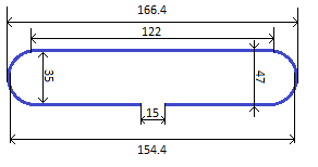
Drawing of the active vibrator (dipole):
All dimensions on the drawings are in millimeters. The distance between the elements is indicated by the centers.
Getting to the manufacture. We take an aluminum profile, retreat an arbitrary distance from its beginning (this distance is necessary for fasteners, I took about 10 cm) and make a through hole with a 5 mm drill. I recommend to immediately make the hole with a drill as small as possible diameter, and then drill out with a 5 mm drill. This is necessary in order not to deviate from the center axis of the profile. Next, we recede 68 mm (according to the drawing) from the center of the hole made earlier and make a through hole with a 6 mm drill (exactly the diameter of the active antenna vibrator). Next, all the holes do drill 5 mm to accommodate the directors.
We begin to make the reflector and the director. Actually all the dimensions are shown on the drawing, just want to give some tips on cutting. Cut the aluminum rod according to the drawing for 2-3 mm more, then expose and fix on the caliper the required length of the element. We file the rods with a flat file to the desired length, periodically controlling the size with a caliper. If the element is tight between the jaws for internal measurements, then you can proceed to the next element.
Rather difficult manufacturing of the loopback vibrator. It is better to fill the cavity of the tube with fine dry sand to avoid fractures of the tube (I did without it, but still it is better not to risk it). To make a circle, you need to find a pipe closest in diameter and bend a copper tube through it. The rest is according to the drawing.
To fix the elements in the profile cavity, I suggest this option. Having inserted an element into the profile cavity perpendicular to it from above the profile, we drill a hole with a 2.5 mm drill and cut the thread with a tap M3 and with a small bolt onto the top we clamp the element above (the main thing is not to overdo it because aluminum is very soft metal). Maybe someone will come up with a simpler or more reliable option, but it seemed to me with my set of tools this is the most successful way of fastening.
All elements need to be centered and check perpendicularity relative to the traverse (booms, as burzhuins like to call it).
Getting to the soldering of the cable drop and loop matching. Cut off a piece of cable RG58 length of 132 mm. We remove 10 mm of external insulation from each side of the cable, taking care not to damage the braid. Then we strip the inner insulation and twist the foil and the braid into one bundle, fold the piece into a loop, connect the braids on each side and seal it well. We clean the internal insulation by 8 mm. The rest I think is clear from the figure:
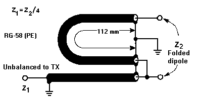
The central cores are soldered to the ends of the active vibrator at the point of its rupture (15 mm in the drawing).
Some explanations. Before you change or throw anything out of the design, ask in the comments so that later there are no reviews “but mnu doesn’t work”. I made everything very precisely according to the calculations, but still the minimum CWS was not at the frequency 881, but 885 MHz, which was quite acceptable for such frequencies. If you make inaccurate, the effect will still be, but not the maximum. At the transmission frequency (average frequency of 824 MHz), the antenna showed itself very poorly, therefore I recommend to place the modem in the best reception zone anyway, because the transmission uses the internal antenna rather than the external antenna.
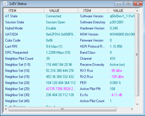
I almost forgot about the tests. To assess the results, the AxesstelPst EvDO BSNL program was used.
The modem is simply plugged into the USB port:
Connect the antenna:

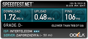
What do we have. The signal is -62 dB, for comparison, if you are standing 20 meters from the BS, the signal will be around -40 dB, -105 dB is almost no signal. Also interesting is the DRC Requested parameter. 3.072 Mbps means that the modem requests the highest possible speed and the BS station will give us the speed depending on the network load. The specific speed depends on the base load, i.e. a further increase in the signal level of the speed improvement will not. The speed in the morning, in the evening will naturally be worse:
Good luck in making. Waiting for questions in the comments.
There was a lot of information on the Internet about self-made external antennas for 3g modems, but I didn’t find anything to travel, so I’m writing these lines. Very touched by people who believe that 3g is such a communication standard such as GSM, but in fact it is just a generation. These same people are looking for antenna drawings for a 3g modem ... So these drawings are not there, or rather they are, but this is the same thing as coming to the car market and persistently demanding a carburetor for a passenger car without even specifying its model. So we will design the antenna for the CDMA2000 standard, whose operating frequencies lie within 821-894 MHz (and not 800 MHz as many people think). The antenna considered here is not suitable for operators MTS Connect, Utel (Kyivstar). Of course, I met the proposals to catch the signal on the “carnation” (it's a quarter-wave vibrator), to make a canned antenna (that's just the catch, according to calculations, not the bank, but the whole bucket is needed), the notorious Kharchenko antennas (a good option when the signal is there is still, but gain leaves much to be desired), etc.
I stopped at the antenna type "Wave Channel", it is Uda-Yagi. The advantages are high gain, low windage, narrowly directed DND, but the disadvantage is extremely significant - very high precision manufacturing is required. The manufactured director will not become a reflector in size, and the active vibrator will not resonate at the frequency we need. The more accurately you do everything, the better the result will be.
The base station is only 3 km from my house, but the windows are facing the other side of the tower and the signal leaves much to be desired. At first I wanted to make an antenna with 8 directors, but it turned out that we need super-precision here because the departure by 1 mm instead of amplification will give attenuation. A 3-directional antenna does not require such precision manufacturing, but has insufficient gain. Therefore, I stopped at the 5-directional wave channel, considering it to be the “golden mean”. The receiving and transmitting channels are quite strongly separated from each other, because the antenna was calculated in the middle of the receiving channel, that is, at 881 MHz. At first, I wanted to design the antenna in the middle of the band as a whole (859 MHz), but since the Yagi is a narrow-band antenna, we will get a peak of the gain in the non-working range and a smaller gain at the operating frequencies.
')
For the design used the program Yagi calculator .
What we need:
- an aluminum square profile with a cross section of 10 mm (bought by me at the epicenter), not aluminum, will fit, but still it is lighter, but does not affect the characteristics of the antenna;
- an aluminum rod with a diameter of 5 mm and a length of 1 meter (another material will fit, including copper, which is even better, but aluminum is the best price / quality ratio);
- a copper tube with a diameter of 6 mm and a half-meter (the outer diameter is indicated, the wall thickness does not matter);
- bolts with a diameter of 3 mm 7 pcs .;
- cable impedance 50 Ohm;
- Adapters, connectors - all individually for each modem, as they say "Google to help."
Separately about the cable. You will not fit a television cable because of its resistance to 75 ohms. More precisely, it can be attached, but due to inconsistency, the loss in the cable is more likely to be greater than the antenna gain. I took 10 meters of the RG58 cable, it is quite cheap, but the loss is 0.6 dB per 1 meter of cable, i.e. I personally lost 6 dB despite the fact that the difference in the signal with and without the antenna is 20 dB. Because saving on the cable is not worth it.
From the tools:
- saw for metal;
- drill;
- tap on the top three;
- drill 2.5; five; 6;
- flat file;
- a caliper (in the extreme case, the ruler will come down);
- arms.
First the drawings:
Red is the reflector, blue is the active vibrator, green is the directors.
Drawing of the active vibrator (dipole):
All dimensions on the drawings are in millimeters. The distance between the elements is indicated by the centers.
Getting to the manufacture. We take an aluminum profile, retreat an arbitrary distance from its beginning (this distance is necessary for fasteners, I took about 10 cm) and make a through hole with a 5 mm drill. I recommend to immediately make the hole with a drill as small as possible diameter, and then drill out with a 5 mm drill. This is necessary in order not to deviate from the center axis of the profile. Next, we recede 68 mm (according to the drawing) from the center of the hole made earlier and make a through hole with a 6 mm drill (exactly the diameter of the active antenna vibrator). Next, all the holes do drill 5 mm to accommodate the directors.
We begin to make the reflector and the director. Actually all the dimensions are shown on the drawing, just want to give some tips on cutting. Cut the aluminum rod according to the drawing for 2-3 mm more, then expose and fix on the caliper the required length of the element. We file the rods with a flat file to the desired length, periodically controlling the size with a caliper. If the element is tight between the jaws for internal measurements, then you can proceed to the next element.
Rather difficult manufacturing of the loopback vibrator. It is better to fill the cavity of the tube with fine dry sand to avoid fractures of the tube (I did without it, but still it is better not to risk it). To make a circle, you need to find a pipe closest in diameter and bend a copper tube through it. The rest is according to the drawing.
To fix the elements in the profile cavity, I suggest this option. Having inserted an element into the profile cavity perpendicular to it from above the profile, we drill a hole with a 2.5 mm drill and cut the thread with a tap M3 and with a small bolt onto the top we clamp the element above (the main thing is not to overdo it because aluminum is very soft metal). Maybe someone will come up with a simpler or more reliable option, but it seemed to me with my set of tools this is the most successful way of fastening.
All elements need to be centered and check perpendicularity relative to the traverse (booms, as burzhuins like to call it).
Getting to the soldering of the cable drop and loop matching. Cut off a piece of cable RG58 length of 132 mm. We remove 10 mm of external insulation from each side of the cable, taking care not to damage the braid. Then we strip the inner insulation and twist the foil and the braid into one bundle, fold the piece into a loop, connect the braids on each side and seal it well. We clean the internal insulation by 8 mm. The rest I think is clear from the figure:
The central cores are soldered to the ends of the active vibrator at the point of its rupture (15 mm in the drawing).
Some explanations. Before you change or throw anything out of the design, ask in the comments so that later there are no reviews “but mnu doesn’t work”. I made everything very precisely according to the calculations, but still the minimum CWS was not at the frequency 881, but 885 MHz, which was quite acceptable for such frequencies. If you make inaccurate, the effect will still be, but not the maximum. At the transmission frequency (average frequency of 824 MHz), the antenna showed itself very poorly, therefore I recommend to place the modem in the best reception zone anyway, because the transmission uses the internal antenna rather than the external antenna.
I almost forgot about the tests. To assess the results, the AxesstelPst EvDO BSNL program was used.
The modem is simply plugged into the USB port:
Connect the antenna:
What do we have. The signal is -62 dB, for comparison, if you are standing 20 meters from the BS, the signal will be around -40 dB, -105 dB is almost no signal. Also interesting is the DRC Requested parameter. 3.072 Mbps means that the modem requests the highest possible speed and the BS station will give us the speed depending on the network load. The specific speed depends on the base load, i.e. a further increase in the signal level of the speed improvement will not. The speed in the morning, in the evening will naturally be worse:
Good luck in making. Waiting for questions in the comments.
Source: https://habr.com/ru/post/161129/
All Articles