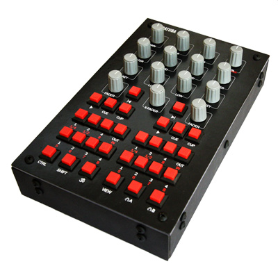
DJ controller
I bring to your attention a device very similar to a full-featured DJ controller, assembled if not entirely from scrap metal, then in any case, without these microcontrollers of yours and other Arduino.
At the DJ console, I was not standing for ten years. And then suddenly shine a couple of favorite tracks, as they say, for the soul. Download Traktor and download tracks - it is simple enough. But the coming joy was immediately overshadowed by the fact that working in this program with a mouse is a pleasure comparable to typing a long letter on a virtual keyboard. Then the keyboard went into action - Traktor is very flexible in adjusting to it, and an arbitrary key can be set to any command. However, this decision was completely unsatisfactory.
It was then that the idea of the project was born and a technical problem was formulated or, if you like, a concept.
')
Since the program is fully controllable from the keyboard, it is possible to take brains from the old USB keyboard and, imitating keystrokes using a set of switches, implement a full-fledged remote control at minimal cost.
The brains of a USB keyboard are, as you know, a small board with a set of contacts huddled in the corner of the case. Here it is in the photo, the truth is already unsoldered and installed in the controller housing.
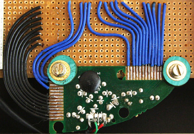
In addition, the standard clave has two transparent sheets superimposed on one another, with conductive paths placed on them and contact pads under each of the keys. When we press a key, the corresponding contacts on the two sheets are closed, resulting in the closing of two contacts on the brain.
In my clave there were two groups of contacts: 8, which with black wires and the response 20 - with blue. With the simple closure of black to blue we achieve everything that the keyboard can do.
“Just a minute! - the thoughtful reader, who you undoubtedly are, exclaims in this place, - But the DJ console is not only buttons, but also knobs! How can imitate the smooth rotation of the knob using the keyboard? "The author should say something like" Follow me, reader, and I will open the doors of the world of electrical engineering for you ... "
Handle design was the most interesting part of the project. Without her, there would be nothing to write about.
So, Traktor offers several options: the simplest is that by holding any button on the keyboard, there will be a gradual increase or decrease in the level of any parameter. However, in this case there is no possibility to regulate the rotation speed. Therefore, I immediately rejected this option. Not worth it and bother with handles, one could simply identify one button to increase, and the other is not a decrease. Not interesting and not practical.
But Traktor is ready to change any parameter stepwise, each time the button is pressed by 1%, 3%, 13%, 25% or 100%. Thus, the task was to design a simple mechanical device that can recognize the direction and speed of rotation, and fractionally closing a pair of contacts in accordance with them.
Of course, I immediately turned my eyes towards computer mice, namely their scrolling. Indeed, scrolling only does that recognize the direction and speed of rotation of the wheel. However, most modern mice are equipped with an optical system of the LED and the sensor. Obviously, it was pointless to look for a short circuit at the output there, and I strictly refused to use electronics, as you remember, for reasons close to ideological ones. Although in reality, it was just a sporting interest and the need to meet the minimum budget. And most importantly, the increasing attacks of inspiration, which led me in a very specific direction.
So, since the mice temporarily disappeared, and other graceful and simple ideas were trampling to the side, hesitating to look into my sinister mind, it was decided to assemble a primitive test stand in order to entertain themselves with at least something.
It's simple. Rotating, the gear rejects the central plate and short-circuits it to one of the side plates. When she slips through the gear teeth, the chain is broken.
Oddly enough, such a thing worked properly. By soldering it to the brains of the keyboard, you could type a word of two letters. For example, "BUT". And indeed, “but” this option did not go to work because of its bulkiness and obvious unreliability. However, there was a positive point - I liked the material that was used for contacts. Galvanized tin or something like that. Cheap, springy, rustproof and perfectly soldered. We will meet with him later in the text.
Then I again turned my gaze, already much more intent, towards the mice. It turned out that many of the oldest and cheapest of the modern are still equipped with mechanical encoders. Here are these:
However, upon closer examination, it turned out that these encoders, by themselves, are not able to recognize the direction of rotation. If anyone is interested, I will tell you how they work. If you are not interested, feel free to skip the next paragraph, it does not apply to the DJ controller.
The encoder has two basic positions: all three contacts are closed and all three are open. When the encoder rotates in a certain direction, there is a short circuit of one pair, and then the second. When rotating in the opposite direction, the second pair closes for an instant first, and then the first pair joins it. In fact, the direction is recognized by the scanty brains of the mouse, which, however, have enough of this short circuit to get up to the appropriate blockage.
Conclusion. Such a mechanical encoder is suitable for recognizing the speed of rotation of the knob (it will simply interrupt the circuit, creating a sequence of pulses), but you will need to add a key to it, specially trained to determine the direction.
As a result, such a construction was born, not devoid, you will agree, of some grace and beautiful with its uncomplicated nature.
The signal from the brains of the keyboard passes through the encoder (which, as you remember, will simply interrupt the circuit). Next, the signal goes to the red posting, soldered to the contact plate (the same galvanized sheet). The plate is glued into the cut on the rubber sleeve (in fact, this is not a sleeve, but a piece of the old gas hose). The sleeve is loosely attached to the aluminum rod that serves as the axle. From above, the sleeve is pressed by the spring, which ensures a reliable connection with the encoder (below) and slightly prevents the sleeve from turning freely on the axis.
From the bottom, the core is riveted, drilled and a pip previously cut off from the mouse wheel is glued into its end, which must then resolutely enter the hole on the encoder (since the original pips were not enough, three of them were made fromoutdated toothpicks).

Encoders are attached to the board, and on the sides of them you can observe the vertical small stands of the side contacts. The racks (ordinary steel wire) are wrapped with silver wire, in order to avoid misunderstandings when passing the signal.
So, the signal from the brain passes through the encoder and enters the contact plate. Ta, while rotating the handle, rests against one of the side posts and begins to turn on the axis, keeping the circuit closed. From the side stands small signal goes back to the brains.
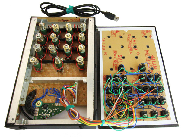
All regulators are installed:
Top view before installing regulators:
Bottom view:
“Just a minute,” the thoughtful reader exclaims at this place for the second time, and will, by the way, be absolutely right, “but what will happen if, after another adjustment, the encoder stops in the closed position and at the same time the record touches one of the racks? “Such a position would be equivalent to sticking one of the keyboard buttons. And although the computer can ignore one or even a few pressed buttons (otherwise it would be impossible to print speed), there is still a limit to everything. If the clamped buttons are located in close proximity, the keyboard stops responding.
Honestly, I never managed to find a simple and reliable solution to this problem. Therefore, I have taken the following two steps. I carried the small stands of the side contacts far away from each other, promising myself that I would “roll back” the handle to the neutral position after another adjustment. And second: it displayed the window of the osdHotkey program. It fits perfectly over the unused part of the Traktora window. The program can show the last key pressed, and if there suddenly runs a string of one letter, it will be a signal to me.
However, after several days of testing such a problem has not been identified.
Here you can tell a funny story. Initially, I looked at the beautiful white buttons of suitable design and value. However, having bypassed all the shops in the town, I managed to gather only thirteen of the required thirty pieces. (I will note in brackets that I live in India and not at all in the capital. The choice of radio components is very limited here and this was an additional argument in favor of maximally simplifying the design).
The required 17 white buttons promised to bring “tomorrow”. But not tomorrow, but after a week, the buttons came red, and about whites I was strictly strictly told to forget forever. I had to buy red and change the design of the top panel. It turned out very nice and even fun.
When I soldered the buttons (and this operation was left for later, as the most trivial) and connected the controller to the computer for the test, the epic file was waiting for me. Nothing worked! Even what worked before. Without giving myself up, I armed myself with a multimeter and after a few seconds found out that the white buttons, unlike the red ones, meanly work for opening ... I had to urgently buy more red ones (they were still on sale).
I quickly abandoned the original idea of making a wooden case in favor of aluminum. However, I did not smile at the prospect of cutting 30 square holes under the buttons in an aluminum plate. And then I came across a wonderful material. Unfortunately, the seller did not speak any of the languages adopted for communication between nations, so the exact name of the material remained a mystery to me. However, googling, I came to the conclusion that this is a laminated finishing panel. For a long time and carefully, I selected color and shade. (And then, just in case, I painted the whole thing black.)
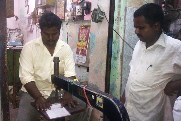
With the help of international gestures and sophisticated facial expressions, I was able to explain to the seller the desired result. After that, he famously cut the plastic on the circular, and then with the help of this, if I may say so, jigsaw cut out the proper holes.
Then the aluminum corners and screws were used, and the hull was ready. The interface of the top panel is printed on a laser printer.
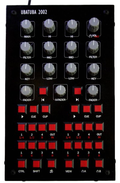
Top view a second before screwing the top panel:
Encoders from mice managed to collect on friends (thanks, friends!). The keyboard was found in the office. The caps of the adjusting knobs and buttons cost540 rubles ~ 10 dollars. The rest building materials about 20 dollars. The total cost of the controller is about 30 dollars (if not to consider the materials purchased, but not the ones that went to work).
Drawings and top panel designs are designed in InDesign. The decoding of keyboard brains and the assignment to each button of a certain function were recorded in an Excel spreadsheet. Hardly these two files can be useful to someone. But if necessary - write.
Performance demonstration (better in 720p HD):
Prehistory
At the DJ console, I was not standing for ten years. And then suddenly shine a couple of favorite tracks, as they say, for the soul. Download Traktor and download tracks - it is simple enough. But the coming joy was immediately overshadowed by the fact that working in this program with a mouse is a pleasure comparable to typing a long letter on a virtual keyboard. Then the keyboard went into action - Traktor is very flexible in adjusting to it, and an arbitrary key can be set to any command. However, this decision was completely unsatisfactory.
It was then that the idea of the project was born and a technical problem was formulated or, if you like, a concept.
')
Since the program is fully controllable from the keyboard, it is possible to take brains from the old USB keyboard and, imitating keystrokes using a set of switches, implement a full-fledged remote control at minimal cost.
Keyboard
The brains of a USB keyboard are, as you know, a small board with a set of contacts huddled in the corner of the case. Here it is in the photo, the truth is already unsoldered and installed in the controller housing.
In addition, the standard clave has two transparent sheets superimposed on one another, with conductive paths placed on them and contact pads under each of the keys. When we press a key, the corresponding contacts on the two sheets are closed, resulting in the closing of two contacts on the brain.
In my clave there were two groups of contacts: 8, which with black wires and the response 20 - with blue. With the simple closure of black to blue we achieve everything that the keyboard can do.
“Just a minute! - the thoughtful reader, who you undoubtedly are, exclaims in this place, - But the DJ console is not only buttons, but also knobs! How can imitate the smooth rotation of the knob using the keyboard? "The author should say something like" Follow me, reader, and I will open the doors of the world of electrical engineering for you ... "
Smooth adjustment knobs
Handle design was the most interesting part of the project. Without her, there would be nothing to write about.
So, Traktor offers several options: the simplest is that by holding any button on the keyboard, there will be a gradual increase or decrease in the level of any parameter. However, in this case there is no possibility to regulate the rotation speed. Therefore, I immediately rejected this option. Not worth it and bother with handles, one could simply identify one button to increase, and the other is not a decrease. Not interesting and not practical.
But Traktor is ready to change any parameter stepwise, each time the button is pressed by 1%, 3%, 13%, 25% or 100%. Thus, the task was to design a simple mechanical device that can recognize the direction and speed of rotation, and fractionally closing a pair of contacts in accordance with them.
Of course, I immediately turned my eyes towards computer mice, namely their scrolling. Indeed, scrolling only does that recognize the direction and speed of rotation of the wheel. However, most modern mice are equipped with an optical system of the LED and the sensor. Obviously, it was pointless to look for a short circuit at the output there, and I strictly refused to use electronics, as you remember, for reasons close to ideological ones. Although in reality, it was just a sporting interest and the need to meet the minimum budget. And most importantly, the increasing attacks of inspiration, which led me in a very specific direction.
So, since the mice temporarily disappeared, and other graceful and simple ideas were trampling to the side, hesitating to look into my sinister mind, it was decided to assemble a primitive test stand in order to entertain themselves with at least something.
It's simple. Rotating, the gear rejects the central plate and short-circuits it to one of the side plates. When she slips through the gear teeth, the chain is broken.
Oddly enough, such a thing worked properly. By soldering it to the brains of the keyboard, you could type a word of two letters. For example, "BUT". And indeed, “but” this option did not go to work because of its bulkiness and obvious unreliability. However, there was a positive point - I liked the material that was used for contacts. Galvanized tin or something like that. Cheap, springy, rustproof and perfectly soldered. We will meet with him later in the text.
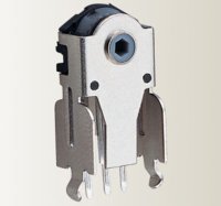
Then I again turned my gaze, already much more intent, towards the mice. It turned out that many of the oldest and cheapest of the modern are still equipped with mechanical encoders. Here are these:
However, upon closer examination, it turned out that these encoders, by themselves, are not able to recognize the direction of rotation. If anyone is interested, I will tell you how they work. If you are not interested, feel free to skip the next paragraph, it does not apply to the DJ controller.
The encoder has two basic positions: all three contacts are closed and all three are open. When the encoder rotates in a certain direction, there is a short circuit of one pair, and then the second. When rotating in the opposite direction, the second pair closes for an instant first, and then the first pair joins it. In fact, the direction is recognized by the scanty brains of the mouse, which, however, have enough of this short circuit to get up to the appropriate blockage.
Conclusion. Such a mechanical encoder is suitable for recognizing the speed of rotation of the knob (it will simply interrupt the circuit, creating a sequence of pulses), but you will need to add a key to it, specially trained to determine the direction.
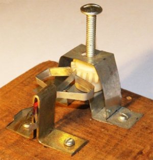
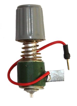
As a result, such a construction was born, not devoid, you will agree, of some grace and beautiful with its uncomplicated nature.
The signal from the brains of the keyboard passes through the encoder (which, as you remember, will simply interrupt the circuit). Next, the signal goes to the red posting, soldered to the contact plate (the same galvanized sheet). The plate is glued into the cut on the rubber sleeve (in fact, this is not a sleeve, but a piece of the old gas hose). The sleeve is loosely attached to the aluminum rod that serves as the axle. From above, the sleeve is pressed by the spring, which ensures a reliable connection with the encoder (below) and slightly prevents the sleeve from turning freely on the axis.
From the bottom, the core is riveted, drilled and a pip previously cut off from the mouse wheel is glued into its end, which must then resolutely enter the hole on the encoder (since the original pips were not enough, three of them were made from
Encoders are attached to the board, and on the sides of them you can observe the vertical small stands of the side contacts. The racks (ordinary steel wire) are wrapped with silver wire, in order to avoid misunderstandings when passing the signal.
So, the signal from the brain passes through the encoder and enters the contact plate. Ta, while rotating the handle, rests against one of the side posts and begins to turn on the axis, keeping the circuit closed. From the side stands small signal goes back to the brains.
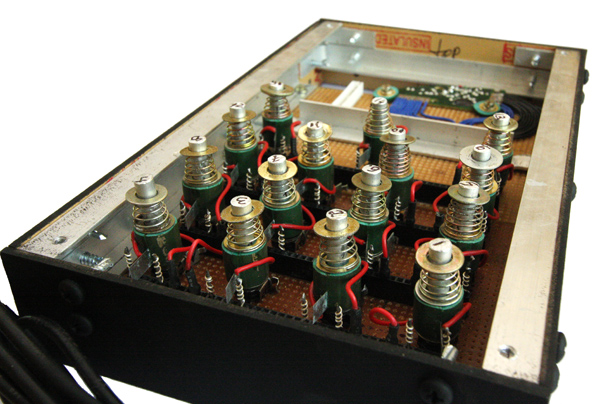
All regulators are installed:
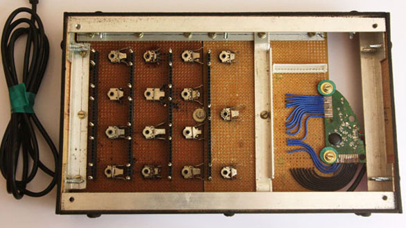
Top view before installing regulators:
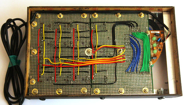
Bottom view:
“Just a minute,” the thoughtful reader exclaims at this place for the second time, and will, by the way, be absolutely right, “but what will happen if, after another adjustment, the encoder stops in the closed position and at the same time the record touches one of the racks? “Such a position would be equivalent to sticking one of the keyboard buttons. And although the computer can ignore one or even a few pressed buttons (otherwise it would be impossible to print speed), there is still a limit to everything. If the clamped buttons are located in close proximity, the keyboard stops responding.
Honestly, I never managed to find a simple and reliable solution to this problem. Therefore, I have taken the following two steps. I carried the small stands of the side contacts far away from each other, promising myself that I would “roll back” the handle to the neutral position after another adjustment. And second: it displayed the window of the osdHotkey program. It fits perfectly over the unused part of the Traktora window. The program can show the last key pressed, and if there suddenly runs a string of one letter, it will be a signal to me.
However, after several days of testing such a problem has not been identified.
Button block
Here you can tell a funny story. Initially, I looked at the beautiful white buttons of suitable design and value. However, having bypassed all the shops in the town, I managed to gather only thirteen of the required thirty pieces. (I will note in brackets that I live in India and not at all in the capital. The choice of radio components is very limited here and this was an additional argument in favor of maximally simplifying the design).
The required 17 white buttons promised to bring “tomorrow”. But not tomorrow, but after a week, the buttons came red, and about whites I was strictly strictly told to forget forever. I had to buy red and change the design of the top panel. It turned out very nice and even fun.
When I soldered the buttons (and this operation was left for later, as the most trivial) and connected the controller to the computer for the test, the epic file was waiting for me. Nothing worked! Even what worked before. Without giving myself up, I armed myself with a multimeter and after a few seconds found out that the white buttons, unlike the red ones, meanly work for opening ... I had to urgently buy more red ones (they were still on sale).
Housing
I quickly abandoned the original idea of making a wooden case in favor of aluminum. However, I did not smile at the prospect of cutting 30 square holes under the buttons in an aluminum plate. And then I came across a wonderful material. Unfortunately, the seller did not speak any of the languages adopted for communication between nations, so the exact name of the material remained a mystery to me. However, googling, I came to the conclusion that this is a laminated finishing panel. For a long time and carefully, I selected color and shade. (And then, just in case, I painted the whole thing black.)
With the help of international gestures and sophisticated facial expressions, I was able to explain to the seller the desired result. After that, he famously cut the plastic on the circular, and then with the help of this, if I may say so, jigsaw cut out the proper holes.
Then the aluminum corners and screws were used, and the hull was ready. The interface of the top panel is printed on a laser printer.
Top view a second before screwing the top panel:
Budget
Encoders from mice managed to collect on friends (thanks, friends!). The keyboard was found in the office. The caps of the adjusting knobs and buttons cost
Bonuses
Drawings and top panel designs are designed in InDesign. The decoding of keyboard brains and the assignment to each button of a certain function were recorded in an Excel spreadsheet. Hardly these two files can be useful to someone. But if necessary - write.
Performance demonstration (better in 720p HD):
Source: https://habr.com/ru/post/160383/
All Articles