We assemble a wi-fi device for controlling electrical appliances with a web server and a JS frontend
Good afternoon, dear habrovchane. In this article I’ll somewhat deviate from my traditional approach to DIY - our main goal will be to get results quickly and efficiently, rather than inventing bicycles for the purpose of self-study, so even people holding a soldering iron for the first time can repeat all this and get a ready device for ~ 1000 rubles and one day.
They say laziness is the engine of progress. This is, in principle, the correct statement - I personally was always strained by the need to get up and go out to turn off the light when I was almost asleep. Therefore, even at the second year of university, I assembled a simple AVR device that allows you to turn the chandelier on and off using any remote control. It still hangs in the same room and has been operating 24/5 for 5 years.
After there was an attempt to get rid of the console - the voice command recognition system, on the same AVR, which I also passed as coursework at the university - she even earned, but not as satisfactory as I would like, so I did not change the awl for soap.
After some time, an understanding was formed that in the vast majority of cases, when I need to turn on or turn off the light, I have either a PC, a tablet, or a communicator within reach and close proximity - therefore, the most convenient way would be to control through them.
I sketched the implementation version on special radio modules, the NRF24L01P is really amazing, for example, the size of the SMD version of this module is only 10x15 mm! At the same time, they are conveniently managed, they have their own protocol, which handles the addressing, multi-reception, auto-confirmation of reception, etc.
Accordingly, in my estimation, there should have been some kind of USB dongle with this module, in the future - connected to a computer with a web server to allow control from mobile devices, and executive devices with response transceivers.
For a very long time, my hands did not reach all of these systems - for a year now I had wires sticking out of the wall, which I closed every time with my hands, including the chandelier, and saying to myself, “Well, I’ll rake up things at work and sit down and scout the boards.
Fortunately, recent projects at work were related to mobile devices, which should have been able to do a little more than the STM32 and any other Cortex M3 can give, and I spent a lot of time working with OpenWRT and devices like the well-loved TL-MR3020 and TL- WR703, about which I recently wrote an article . Together with this experience, it came to the realization that such problems are solved incredibly quickly and very effectively with the help of devices with linux and wi-fi on board. If only because Wi-Fi provides much more convenient (and in the case of the need to transfer video / audio - practically the only available) wireless communication devices supported by all modern devices.
Of course, if there are dozens of management objects, it makes sense to make more stupid actuators on custom modules, and leave servers with Linux to act as nodes. But in the case when we make a product for real use at home, and not based on hypothetical objects, this approach will only lead to a terrible loss of time and money.
So, let's put together a device in a day that will enable turning on and off a household appliance (up to 1.6 kW of consumption) via Wi-Fi, with a beautiful frontend and without a lot of fuss with boards, firmware and drivers.
Let's start, contrary to tradition, not with hardware, but with the software part, because it is simple enough and you can check it immediately after purchasing the router, even without disassembling it.
I hope that by this time you have already bought the TL-MR3020 and, perhaps, even read my article on rebuilding the kernel. In fact, you can do without even rebuilding, just flip it with the firmware from the official OpenWRT project wiki - if you later have a desire, you can easily create your firmware by embedding the necessary scripts into it.
So, how will our device be arranged?
')
Let's start. At this point, you should already change the router to OpenWRT and connect to it via an Ethernet cable.
Go through SSH / WinSCP to the router and go to / etc
for this we go to / etc / config / network and write there
This will ensure that the wi-fi controller of the IP router receives DHCP from our home Wi-Fi distributor in the face of another router.
In / etc / config / wireless, caring first-start scripts have already generated the radio settings, it remains to comment out the line #option disabled 1 including the wi-fi module and in the section below, the interface descriptor, write something like
These settings are for WPA2-PSK. For WPA-PSK encryption will be psk, for the open point of none, for WEP, respectively, wep - it is better to read in more detail on the official wiki here and here .
We check that everything is good with the help
If everything is OK, iwconfig will tell you that you are connected to your access point, after which it should be cut off from the e-mail and continue wi-fi setup.
Now we need to give access to GPIO pins from user space. The kernel can do this by itself, there is no need to do anything for this, but the GPIO is already captured by the flashing driver by LEDs. If you wish, you can not touch the LEDs and their driver, because, according to the wiki , there are several unused GPIOs pulled up to the ground, the pull-up of which can be unsoldered, and then used for their own purposes. In this case, you do not need to unload the driver; you only need to export the GPIO (shown below). But we will use pins with LEDs to immediately see the result of the works:
Writing to /etc/rc.local
With this we unload the driver that captures the resources, then we say that we want to use a pin 0 in the user space, set it up for output and output 0 there, turning off the LED. Now you can ignite it with a command
And pay off - this one:
Just do not forget that our creaking has not yet been completed, so we first reboot the router with the reboot command, checking at the same time how wi-fi rises after a reboot.
If you rebuilt the kernel and embedded mini-httpd into it, then go straight to the configuration, if not, install it from the repository
Now we make some minor changes to /etc/mini-httpd.conf , so that its first line looks like
Now the server will kick everything in / www / cgi-bin / and whose name ends in .sh as a command, translating its response to the browser.
In case we don’t want to reach out to wi-fi, we’ll hang a duplicate action on a single button: in /etc/hotplug2.rules, uncheck the word “ buttons” so that pressing the buttons calls up scripts from the corresponding folder, the line should now look like this:
After that, go to /etc/hotplug.d/ , create the button folder there, and in it the buttons script (not forgetting to set it to execute with the command chmod + x buttons !) With the following contents:
Now pressing the button will toggle the status of the LED. If desired, you can make the LED under this button glow in antiphase with the manager, that is, with the chandelier extinguished, the hardware enable button is lit to simplify its search in the dark - for this simply export pin 26 to rc.local as well as pin 0 exported and add similar output lines 1/0 to its value next to the zero pin in value .
This can be checked right away - if you did everything correctly, then pressing the button will cause a change in the state of the LED.
Now we leave / etc and go to / www , where we create the cgi-bin directory , and in it is the light-control.sh script, which we do chmod + x with the following contents:
The first two lines after #! / Bin / sh are required for a CGI script - we tell the browser that everything is ok and we will now issue a html, after which we’ll send two helms in accordance with the requirements of the standard.
Then we take the parameters from the $ QUERRY_STRING variable, where the careful mini-httpd put them, and parse each into name and value . In general, only one parameter will be used here, but let the code be in a more general form, in case we decide to expand.
Next, we check - if they give us the action = on , then we light the diode, if action = off - we extinguish.
And after that we always return what we read from value - 1 if the diode is on, 0 - if not. Thus, if we pull our script from the outside with any parameter except action = on / off or no parameter at all, we will get the current status of the LED from it.
We throw in the directory / www downloaded from off. jquery site - it’s really convenient to do Ajax requests - I saw all these java-scripts for the first time in my life (because this is the area farthest from my studies and interests), but in 5 minutes I’ve mastered the actions I’ve been using Google . Save jquery as jquery.js
We also keep the pictures below under the names of lamp_on.jpg and lamp_off.jpg , which symbolize our chandelier - made them from a picture taken from Google by cutting it into two parts and easily fitting to each other. If desired, you can use any pictures.


In the same place we create index.html in which we write
Here we post on the page two initially invisible pictures with a lit and extinguished lamp, and the Java script after the start requests the CXI (using the action = none parameter) the current status, and transfer the result to the ProcessResult , which activates a particular picture. The same function is called after asynchronous status switch requests (which are executed in the event handlers for the click on pictures), and a timer is set, which every 2000 ms the script pulls about the status to display the actual data when someone changes them from another page or a hardware button.
That's all - now you can go to the browser on our router's IP and enjoy the beautiful page that controls the LED. If you click on the button of the router when the page is open and wait for 2 seconds, the picture itself will change due to a request made by the timer.
At this point, the software is completed, go to the piece of iron.
As for the hardware, the situation is twofold. Actually, we have the simplest circuit - the control circuit of a solid-state relay is essentially the same LED, and all that is needed is to ensure that enough current flows through it. In S202S02, this is at least 8 mA.
Unfortunately, it’s impossible to get it directly from GPIO - the voltage on the GPIO is 2.6V, after which there is a resistor in a very small case of 260 Ohms and an LED with a voltage drop of about 1.5V. Thus, about 4-5 mA flows through it. The drop in S202S02 is from 1.2 to 1.4V, so something will be about the same there. You can, of course, search for a resistor in the same package, but of a smaller nominal, solder it, and load the unfortunate GPIO at 10 mA, but it’s better to go in a simpler way - the base-emitter of the NPN transistor will perform the LED role, through which at 0.75V a current of 0.7 mA will flow and in the collector we will turn on the control relay circuit.
The problems are different. There are actually two of them:
With regard to paragraph 1. Textolite, which performed the scheme, quite simply shitty.
The tracks and pads breaks instantly, the solder - to match the PCB - begins to melt when this very PCB is starting to burn.
With regard to paragraph 2. If the case is 5 mm higher - there would be no problems. But alas, the power supply capacitors and the pulse transformer are too high for the case to close.
Unfortunately, I did not find any perfect magical solution that allows you to cram nevpihuemoe beautifully and quickly into the body. There are a lot of kostylny options - from buying a plastic case into which it all fits (normal, in general, an option), and ending with blue electrical tape and rubber bands to keep the original case intact.
I chose something in between - because I still had polymorph-plastic, I laid a narrow strip of it around the perimeter of the original case and pressed the lid into it.
So in this matter, I recommend everyone to find a solution that suits him. Of course, if you use a large case, or attach a power supply outside of this small one, you don’t have to completely unplug the connectors, I’ll just tell you what I did.
So that the board could fit into the case along with the power supply, I soldered all the connectors (Ethernet, USB-Host, micro-USB-Power) from it, as well as the isolation from the power supply. The board has become sharply flat. If you do this - be very, very attentive. I paid for my carelessness by setting the flow from the hairdryer too strong, as a result of which the critical U5 converter giving 3.3 in the system was repaired. Moreover, he was blown to the floor and had to look for him for a long time - but, fortunately, he managed to solder him back.
Pay attention to the jumper R113 (circled in red) - by default it is open. Having closed it, we will be able to supply power to the router via the USB-Host connector - and there it’s easier and more reliable to solder there. he is not SMD. Therefore, we close the R113 and calmly solder two wires for power supply to the holes from under the connector.
Noticed how hard it is to solder the wire in the "earthen" hole? It is connected to the polygons of the earth on all layers where they are - the heat sink is crazy, my soldering iron barely coped.
And this is how the inside of the power supply looks like (next to the router board for scale)
We unsolder two sickly wires, which previously went to the plug, and solder there something more reliable, which we will then connect to the 220V network. At the same time, we unsolder its USB connector, as we connect it directly to our router power wires.
We prepare the relay by soldering so that later the power wires do not touch anything. I soldered like this:
After soldering we push in heat shrinkage, or we wrap it up with tape, or cover it with some kind of sealant or something similar (by the way, this very sealant can be seen on the photo of the power supply unit - it was originally, the Chinese also care about TB).
Then we solder the transistor - I took the first 2N6517 under my arm and soldered it with the base to the site where LED4 had written + , with the emitter - to the second.
So here. So do not. Because one wrong movement is enough and you will break both platforms, then you will have to be soldered to the resistor. It is better to solder thin wiring to both sites, fasten them on the board and bring to a safe place. And - yes - if you solder inaccurately, then you risk, like me, touching the conclusions of the memory chip with a soldering iron and shorting them. After that, you will curse your crooked hands and try to clean them with tin extractors, braids for brazing, needles - it is checked on yourself for an hour. Fortunately, it was possible to clear it, but it was incredibly tense.
It remains quite a bit - now we have an “open collector” type output (the remaining output of the transistor), to which we solder the resistor at the rate of dropping 1.3 volts on the optocoupler - that is, when powered from 3.3V (they are easiest to take, on the non-soldered P1 connector on the right in the picture above is the fourth pin), we have to provide a current somewhere in 10 mA, which means exactly 200 ohms.
Now we gently place the power supply unit with the conder down onto the router's board, not forgetting to lay a piece of paper - the metal top of the feeder should not be energized, but it can bridge something, so let it be a piece of paper. The power wires of the router are soldered to the holes from the USB connector on the unit, the positive pin of the relay is soldered to 3.3V (hole 4 on P1 ), the negative pin through a 200 ohm resistor to the collector of the transistor.
We cut one of the lids of the lid so that it does not rest on the power supply, the protrusion intended for pressing the button is increased by cutting the rod from the handle or the same polymorph.
Well, we press it all with a lid, fixing it as you like - with polymorph, electrical tape, rubber bands - which is enough for imagination and materials.
It remains to bring 220V to the power wires of the router, and switch the switched relay wires instead of the chandelier switch or any other household appliance.
Happened? Congratulations, now in your chandelier there is a web server with CGI running Linux, giving users a web frontend in JavaScript, and all of this is about 1000 rubles and one day of fuss.
Introduction
They say laziness is the engine of progress. This is, in principle, the correct statement - I personally was always strained by the need to get up and go out to turn off the light when I was almost asleep. Therefore, even at the second year of university, I assembled a simple AVR device that allows you to turn the chandelier on and off using any remote control. It still hangs in the same room and has been operating 24/5 for 5 years.
After there was an attempt to get rid of the console - the voice command recognition system, on the same AVR, which I also passed as coursework at the university - she even earned, but not as satisfactory as I would like, so I did not change the awl for soap.
After some time, an understanding was formed that in the vast majority of cases, when I need to turn on or turn off the light, I have either a PC, a tablet, or a communicator within reach and close proximity - therefore, the most convenient way would be to control through them.
I sketched the implementation version on special radio modules, the NRF24L01P is really amazing, for example, the size of the SMD version of this module is only 10x15 mm! At the same time, they are conveniently managed, they have their own protocol, which handles the addressing, multi-reception, auto-confirmation of reception, etc.
Accordingly, in my estimation, there should have been some kind of USB dongle with this module, in the future - connected to a computer with a web server to allow control from mobile devices, and executive devices with response transceivers.
For a very long time, my hands did not reach all of these systems - for a year now I had wires sticking out of the wall, which I closed every time with my hands, including the chandelier, and saying to myself, “Well, I’ll rake up things at work and sit down and scout the boards.
Fortunately, recent projects at work were related to mobile devices, which should have been able to do a little more than the STM32 and any other Cortex M3 can give, and I spent a lot of time working with OpenWRT and devices like the well-loved TL-MR3020 and TL- WR703, about which I recently wrote an article . Together with this experience, it came to the realization that such problems are solved incredibly quickly and very effectively with the help of devices with linux and wi-fi on board. If only because Wi-Fi provides much more convenient (and in the case of the need to transfer video / audio - practically the only available) wireless communication devices supported by all modern devices.
Of course, if there are dozens of management objects, it makes sense to make more stupid actuators on custom modules, and leave servers with Linux to act as nodes. But in the case when we make a product for real use at home, and not based on hypothetical objects, this approach will only lead to a terrible loss of time and money.
So, let's put together a device in a day that will enable turning on and off a household appliance (up to 1.6 kW of consumption) via Wi-Fi, with a beautiful frontend and without a lot of fuss with boards, firmware and drivers.
Software part
Let's start, contrary to tradition, not with hardware, but with the software part, because it is simple enough and you can check it immediately after purchasing the router, even without disassembling it.
I hope that by this time you have already bought the TL-MR3020 and, perhaps, even read my article on rebuilding the kernel. In fact, you can do without even rebuilding, just flip it with the firmware from the official OpenWRT project wiki - if you later have a desire, you can easily create your firmware by embedding the necessary scripts into it.
So, how will our device be arranged?
- Since it is important for us to keep the minimum number of parts, we will not use any external flash drives and hubs, so the size of the available memory is limited to 4 MB, of which, usually, about 1-1.5 MB is free.
- Taking into account point 1, we’ll choose the most lightweight web server that supports CGI - the ideal choice was a 20-kilobyte mini-httpd without any add-ons.
- As a cgi-script, we will use the usual Bashiv scripts. In principle, the place allows you to put a minimum python assembly. True, I'm afraid, without rebuilding the kernel, you will not do it - because Everything that you install after the firmware is installed in JFFS, then it takes much more than if it was built initially in SquashFS. As an experiment, I built both python-mini and mini-httpd directly into the image, throwing out all unnecessary - with the JFFS image build, the system threw the size overruns, leaving incomplete pieces as a memory, but the SquashFS-image was assembled normally, leaving me ~ 250 KB of free space is enough for our needs. Another note is that starting python from an internal flash drive is much slower than starting a bash interpreter (and obviously a slower than from an external USB flash drive, the SPI interface affects), so when using Python scripts for CGI, the response will be about 1 second - not very critical, but slightly annoying. However, if I were writing something more complicated than jerking with one GPIO, I would be much more annoyed by the huge and nasty bash script, and I would prefer to come to terms with the second start of the python interpreter
- A bash script will pull one of the available GPIOs on which the LED hangs. After that we’ll unsolder the LED and add a solid-state relay to it, the control circuit of which is essentially the same LED.
- Index.html will contain a small js-code to display a beautiful image with a light bulb that will light up / go out when pressed, performing an asynchronous query to the CGI script, and will also pull it every N seconds, in case someone has already lit the light bulb from another computer - to update the image in accordance with the status.
- We power it all on the power supply unit that comes with it, having first disassembled it, removing the module itself from the case to reduce the size of the final device. This step is optional, if you want - you can feed as you like.
')
Let's start. At this point, you should already change the router to OpenWRT and connect to it via an Ethernet cable.
Go through SSH / WinSCP to the router and go to / etc
We configure wi-fi
for this we go to / etc / config / network and write there
config interface 'wlan' option proto 'dhcp' This will ensure that the wi-fi controller of the IP router receives DHCP from our home Wi-Fi distributor in the face of another router.
In / etc / config / wireless, caring first-start scripts have already generated the radio settings, it remains to comment out the line #option disabled 1 including the wi-fi module and in the section below, the interface descriptor, write something like
config wifi-iface option device radio0 option network wlan option mode sta option ssid --- option encryption psk2 option key -- These settings are for WPA2-PSK. For WPA-PSK encryption will be psk, for the open point of none, for WEP, respectively, wep - it is better to read in more detail on the official wiki here and here .
We check that everything is good with the help
wifi down wifi iwconfig wlan0 If everything is OK, iwconfig will tell you that you are connected to your access point, after which it should be cut off from the e-mail and continue wi-fi setup.
Configuring GPIO
Now we need to give access to GPIO pins from user space. The kernel can do this by itself, there is no need to do anything for this, but the GPIO is already captured by the flashing driver by LEDs. If you wish, you can not touch the LEDs and their driver, because, according to the wiki , there are several unused GPIOs pulled up to the ground, the pull-up of which can be unsoldered, and then used for their own purposes. In this case, you do not need to unload the driver; you only need to export the GPIO (shown below). But we will use pins with LEDs to immediately see the result of the works:
Writing to /etc/rc.local
rmmod leds_gpio echo 0 > /sys/class/gpio/export echo out > /sys/class/gpio/gpio0/direction echo 0 > /sys/class/gpio/gpio0/value With this we unload the driver that captures the resources, then we say that we want to use a pin 0 in the user space, set it up for output and output 0 there, turning off the LED. Now you can ignite it with a command
echo 1 > /sys/class/gpio/gpio0/value And pay off - this one:
echo 0 > /sys/class/gpio/gpio0/value Just do not forget that our creaking has not yet been completed, so we first reboot the router with the reboot command, checking at the same time how wi-fi rises after a reboot.
We configure mini-httpd
If you rebuilt the kernel and embedded mini-httpd into it, then go straight to the configuration, if not, install it from the repository
opkg update opkg install mini-httpd Now we make some minor changes to /etc/mini-httpd.conf , so that its first line looks like
cgipat=cgi-bin/**.sh Now the server will kick everything in / www / cgi-bin / and whose name ends in .sh as a command, translating its response to the browser.
Customize hardware button
In case we don’t want to reach out to wi-fi, we’ll hang a duplicate action on a single button: in /etc/hotplug2.rules, uncheck the word “ buttons” so that pressing the buttons calls up scripts from the corresponding folder, the line should now look like this:
SUBSYSTEM ~~ (^net$|^input$|button$|^usb$|^ieee1394$|^block$|^atm$|^zaptel$|^tty$) { After that, go to /etc/hotplug.d/ , create the button folder there, and in it the buttons script (not forgetting to set it to execute with the command chmod + x buttons !) With the following contents:
#!/bin/sh if [ "$BUTTON" = "wps" ]; then if [ "$ACTION" = "released" ]; then state=`cat /sys/class/gpio/gpio0/value` if [ "$state" = "0" ]; then echo 1 > /sys/class/gpio/gpio0/value else echo 0 > /sys/class/gpio/gpio0/value fi fi fi Now pressing the button will toggle the status of the LED. If desired, you can make the LED under this button glow in antiphase with the manager, that is, with the chandelier extinguished, the hardware enable button is lit to simplify its search in the dark - for this simply export pin 26 to rc.local as well as pin 0 exported and add similar output lines 1/0 to its value next to the zero pin in value .
This can be checked right away - if you did everything correctly, then pressing the button will cause a change in the state of the LED.
Writing a CGI script
Now we leave / etc and go to / www , where we create the cgi-bin directory , and in it is the light-control.sh script, which we do chmod + x with the following contents:
#!/bin/sh echo "content-type: text/html" echo "" input=$(echo $QUERY_STRING | tr "&" "\n") for param in $input do name=`echo $param | cut -f 1 -d "="` value=`echo $param | cut -f 2 -d "="` if [ "$name" = "action" ]; then if [ "$value" = "on" ]; then echo 1 > /sys/class/gpio/gpio0/value elif [ "$value" = "off" ]; then echo 0 > /sys/class/gpio/gpio0/value fi fi done cat /sys/class/gpio/gpio0/value The first two lines after #! / Bin / sh are required for a CGI script - we tell the browser that everything is ok and we will now issue a html, after which we’ll send two helms in accordance with the requirements of the standard.
Then we take the parameters from the $ QUERRY_STRING variable, where the careful mini-httpd put them, and parse each into name and value . In general, only one parameter will be used here, but let the code be in a more general form, in case we decide to expand.
Next, we check - if they give us the action = on , then we light the diode, if action = off - we extinguish.
And after that we always return what we read from value - 1 if the diode is on, 0 - if not. Thus, if we pull our script from the outside with any parameter except action = on / off or no parameter at all, we will get the current status of the LED from it.
We write frontend
We throw in the directory / www downloaded from off. jquery site - it’s really convenient to do Ajax requests - I saw all these java-scripts for the first time in my life (because this is the area farthest from my studies and interests), but in 5 minutes I’ve mastered the actions I’ve been using Google . Save jquery as jquery.js
We also keep the pictures below under the names of lamp_on.jpg and lamp_off.jpg , which symbolize our chandelier - made them from a picture taken from Google by cutting it into two parts and easily fitting to each other. If desired, you can use any pictures.
In the same place we create index.html in which we write
<html> <head> <script type="text/javascript" src="jquery.js"></script> <script type="text/javascript"> function LampImgOn() { $('#lamp_off').hide(); $('#lamp_on').show(); } function LampImgOff() { $('#lamp_on').hide(); $('#lamp_off').show(); } function ProcessResult(data) { if(data=="1\n") LampImgOn(); else LampImgOff(); } $(document).ready(function() { $.ajaxSetup({ cache: false }); $('#lamp_on').hide(); jQuery.get('/cgi-bin/light-control.sh', {'action': 'none'}, ProcessResult); $('#lamp_on').click(function() { jQuery.get('/cgi-bin/light-control.sh', {'action': 'off'}); LampImgOff(); }) $('#lamp_off').click(function() { jQuery.get('/cgi-bin/light-control.sh', {'action': 'on'}); LampImgOn(); }) window.setInterval("jQuery.get('/cgi-bin/light-control.sh', {'action': 'none'}, ProcessResult)",2000); }); </script> </head> <body bgcolor="#000000"> <img id = 'lamp_off' src = 'lamp_off.jpg' height = '40%' style='display:none'> <img id = 'lamp_on' src = 'lamp_on.jpg' height = '40%' style='display:none'> </body> </html> Here we post on the page two initially invisible pictures with a lit and extinguished lamp, and the Java script after the start requests the CXI (using the action = none parameter) the current status, and transfer the result to the ProcessResult , which activates a particular picture. The same function is called after asynchronous status switch requests (which are executed in the event handlers for the click on pictures), and a timer is set, which every 2000 ms the script pulls about the status to display the actual data when someone changes them from another page or a hardware button.
That's all - now you can go to the browser on our router's IP and enjoy the beautiful page that controls the LED. If you click on the button of the router when the page is open and wait for 2 seconds, the picture itself will change due to a request made by the timer.
At this point, the software is completed, go to the piece of iron.
Iron
As for the hardware, the situation is twofold. Actually, we have the simplest circuit - the control circuit of a solid-state relay is essentially the same LED, and all that is needed is to ensure that enough current flows through it. In S202S02, this is at least 8 mA.
Unfortunately, it’s impossible to get it directly from GPIO - the voltage on the GPIO is 2.6V, after which there is a resistor in a very small case of 260 Ohms and an LED with a voltage drop of about 1.5V. Thus, about 4-5 mA flows through it. The drop in S202S02 is from 1.2 to 1.4V, so something will be about the same there. You can, of course, search for a resistor in the same package, but of a smaller nominal, solder it, and load the unfortunate GPIO at 10 mA, but it’s better to go in a simpler way - the base-emitter of the NPN transistor will perform the LED role, through which at 0.75V a current of 0.7 mA will flow and in the collector we will turn on the control relay circuit.
The problems are different. There are actually two of them:
- You need to unsolder the LED (we have a LED4 LED) and solder our transistor instead
- It is necessary to pack something up into the case of the relay (well, it is not difficult, it is shallow) and the inside of the power supply.
With regard to paragraph 1. Textolite, which performed the scheme, quite simply shitty.
The tracks and pads breaks instantly, the solder - to match the PCB - begins to melt when this very PCB is starting to burn.
With regard to paragraph 2. If the case is 5 mm higher - there would be no problems. But alas, the power supply capacitors and the pulse transformer are too high for the case to close.
Unfortunately, I did not find any perfect magical solution that allows you to cram nevpihuemoe beautifully and quickly into the body. There are a lot of kostylny options - from buying a plastic case into which it all fits (normal, in general, an option), and ending with blue electrical tape and rubber bands to keep the original case intact.
I chose something in between - because I still had polymorph-plastic, I laid a narrow strip of it around the perimeter of the original case and pressed the lid into it.
So in this matter, I recommend everyone to find a solution that suits him. Of course, if you use a large case, or attach a power supply outside of this small one, you don’t have to completely unplug the connectors, I’ll just tell you what I did.
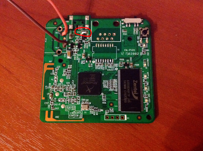
So that the board could fit into the case along with the power supply, I soldered all the connectors (Ethernet, USB-Host, micro-USB-Power) from it, as well as the isolation from the power supply. The board has become sharply flat. If you do this - be very, very attentive. I paid for my carelessness by setting the flow from the hairdryer too strong, as a result of which the critical U5 converter giving 3.3 in the system was repaired. Moreover, he was blown to the floor and had to look for him for a long time - but, fortunately, he managed to solder him back.
Pay attention to the jumper R113 (circled in red) - by default it is open. Having closed it, we will be able to supply power to the router via the USB-Host connector - and there it’s easier and more reliable to solder there. he is not SMD. Therefore, we close the R113 and calmly solder two wires for power supply to the holes from under the connector.
Noticed how hard it is to solder the wire in the "earthen" hole? It is connected to the polygons of the earth on all layers where they are - the heat sink is crazy, my soldering iron barely coped.
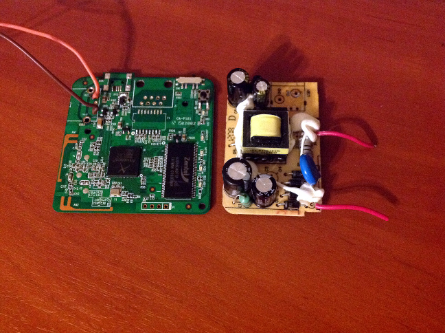
And this is how the inside of the power supply looks like (next to the router board for scale)
We unsolder two sickly wires, which previously went to the plug, and solder there something more reliable, which we will then connect to the 220V network. At the same time, we unsolder its USB connector, as we connect it directly to our router power wires.
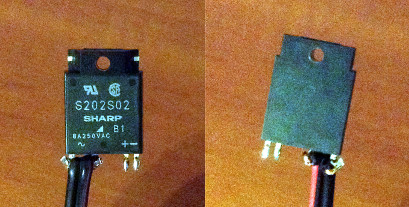
We prepare the relay by soldering so that later the power wires do not touch anything. I soldered like this:
After soldering we push in heat shrinkage, or we wrap it up with tape, or cover it with some kind of sealant or something similar (by the way, this very sealant can be seen on the photo of the power supply unit - it was originally, the Chinese also care about TB).
Then we solder the transistor - I took the first 2N6517 under my arm and soldered it with the base to the site where LED4 had written + , with the emitter - to the second.
So here. So do not. Because one wrong movement is enough and you will break both platforms, then you will have to be soldered to the resistor. It is better to solder thin wiring to both sites, fasten them on the board and bring to a safe place. And - yes - if you solder inaccurately, then you risk, like me, touching the conclusions of the memory chip with a soldering iron and shorting them. After that, you will curse your crooked hands and try to clean them with tin extractors, braids for brazing, needles - it is checked on yourself for an hour. Fortunately, it was possible to clear it, but it was incredibly tense.
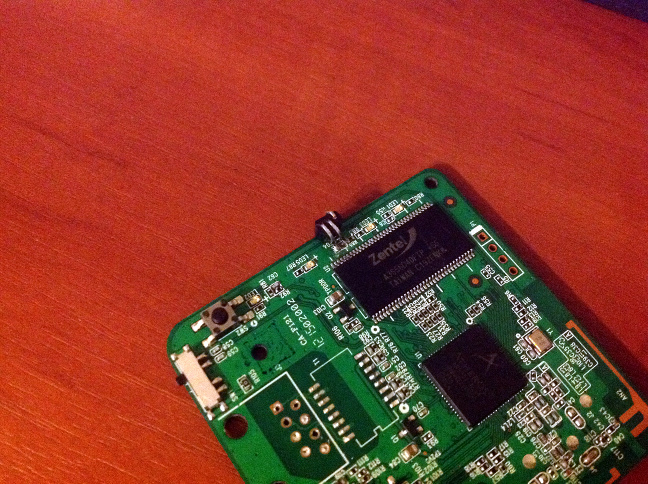
It remains quite a bit - now we have an “open collector” type output (the remaining output of the transistor), to which we solder the resistor at the rate of dropping 1.3 volts on the optocoupler - that is, when powered from 3.3V (they are easiest to take, on the non-soldered P1 connector on the right in the picture above is the fourth pin), we have to provide a current somewhere in 10 mA, which means exactly 200 ohms.
Now we gently place the power supply unit with the conder down onto the router's board, not forgetting to lay a piece of paper - the metal top of the feeder should not be energized, but it can bridge something, so let it be a piece of paper. The power wires of the router are soldered to the holes from the USB connector on the unit, the positive pin of the relay is soldered to 3.3V (hole 4 on P1 ), the negative pin through a 200 ohm resistor to the collector of the transistor.
We cut one of the lids of the lid so that it does not rest on the power supply, the protrusion intended for pressing the button is increased by cutting the rod from the handle or the same polymorph.
Well, we press it all with a lid, fixing it as you like - with polymorph, electrical tape, rubber bands - which is enough for imagination and materials.
It remains to bring 220V to the power wires of the router, and switch the switched relay wires instead of the chandelier switch or any other household appliance.
Happened? Congratulations, now in your chandelier there is a web server with CGI running Linux, giving users a web frontend in JavaScript, and all of this is about 1000 rubles and one day of fuss.
Source: https://habr.com/ru/post/159745/
All Articles