We solder a “smart” car PSU on 5v with USB charging and automatic on / off
 I am a lazy person and I love comfort, so I love all sorts of automation. In the car I have a DVR, sometimes I use a navigator, often I need to charge my phone or tablet to myself or my family / acquaintance. As a result of these needs, the entire machine is shrouded in wires and charges, but you should always think that you should pull out the cigarette lighter from the tee and that the next charge did not lose contact in the cigarette lighter. Of course, little by little in the car there was a tangle of wires and charge, and this is not only not aesthetically pleasing, it can also attract drug addicts.
At one point, it all got enough and it was decided to do something universal.
Task:
- Output voltage 5.1V
- Current not less than 3A (phone, 0.6A, DVR - 0.3A, iPad - 2A)
- Automatic switching on of power supply when the engine starts
- Manual power on
- Automatic power off after 15-30 minutes after turning off the engine (with the possibility to extend this time). So that you can leave the recorder in the car without the need to turn it off / on every time.
- Automatic shutdown of BP when the battery is strongly discharged
- Manual power off
Whistles and fakesLight and sound alarm- A sufficient number of USB-connectors (at least 4 pcs.) In an easily accessible place but without distortion over the cabin
- Normal (like native charging) charge of Samsung and Apple devices
- Without a cigarette lighter.
Decision:
The solution is quite obvious. A microcontroller for automation and some kind of voltage converter, but the converter should have the ability to turn on / off the operation of logic levels.
')
With the placement in the car it was a little more difficult, at first I wanted to insert the USB into the cup holder, but then threw this idea away, because not aesthetically, plus the glass will not be delivered, and even the next coils of wires were not pleasing. Then I drew attention to the armrest and drawer located in it. It was what you need! The box itself is pulled out - it means you can easily maintain it, there is a lot of space in the armrest itself - it means the electronics will quietly fit. USB connectors can be easily inserted into the side of the box and unnecessary charging wires can be hidden from the connectors in the box.
In addition to USB connectors for charging, power was required for the DVR. For this, a wire was stretched from the armrest to the rear-view mirror, another USB connector was pasted on the mirror and a connector for the DVR was inserted.
If the placement of connectors, everything was pretty clear, then there were some minor problems with the electronics.
First was the LM2596.

A little earlier, I ordered on eBay a few shawls of adjustable power supplies assembled on the LM2596 chip. I needed to do a charging for the iPad in order to charge it with a large current (like my own - 10W). I did the charging, everything worked fine, charging gave something around 2.1A to 5.1V (with an input voltage of about 12-13V - the UPS battery), but there was one drawback - it was terribly warming up! The entire board was heated so that it melted a plastic box, in which the board itself was darkened (despite the fact that the radiator was stuck there ). After measuring the efficiency, it turned out that with a large current, the efficiency was about 60%, which did not suit us at all.
An additional bad point was that these Chinese handkerchiefs did not pull out the control leg separately and would have to solder one leg of the chip from the board and solder the wires to it.
What to do with the modules on the LM2596 is not clear.
KIS-3R33S - a miracle of Chinese "conversion" technologies.
Wool eBay, I often met some modules KIS-3R33S, in the description of which indicated that they issue 3A. The cost of the modules also inspired - with the purchase of 10 pieces, each module costs about 50-90 cents with free shipping. After reading Yandex, it became clear that this is a pretty good module on the MP2307 microcircuit, which can be converted into an adjustable converter, and from the hinged elements only two capacitors are needed - the input and the output.
And what is important - even with a load of 2A, it is absolutely not heated!
All sold modules are soldered. From where they take them in such numbers is completely incomprehensible;)
Those. parameters of the chip MP2307
In general, for some five kopecks a handful of modules was acquired and the work began to boil.Input voltage - 4.75-23V
Output Voltage - 0.925-20V
Maximum continuous output current (short-term) - 3A (4A)
Conversion frequency - 340kHz
Efficiency - up to 95%
Built-in protection against short circuit and overheating
Control input
Output Voltage - 0.925-20V
Maximum continuous output current (short-term) - 3A (4A)
Conversion frequency - 340kHz
Efficiency - up to 95%
Built-in protection against short circuit and overheating
Control input
Preparation of BP.
By default, the KIS-3R33S module is set to 3.3V, so you need to adapt the module a little. There are various options for reworking this module ( for example ), but I decided to get by with minimal rework. Armed with a datasheet and a KIS-3R33S schematic, I made this list of rework:

- We open the module
- Remove the resistor and zener diode marked in red. (some remove the capacitor marked in yellow - I did not)
- Solder (right inside, so that the case can be closed later) "output" resistor (0.125 watt) R between the minus and the input of the ADJ module. Resistor purple. A resistor with a nominal value of 9.1 to 10 kom, depending on the resistor there will be a different voltage (from 5.28V to 5.15V, respectively). This resistor is connected in series with the already-installed resistor at 3.3k (i.e., the total resistance of the resistors is 3.3 + 9.1 = 12.4) and parallel to resistor R1, due to which their total resistance drops and the voltage at the output of the chip increases.
- Putting the module back
- To the input and output of the module we solder electrolytic capacitors of approximately the indicated capacitances. The voltage of the capacitors can not be taken less, but more can be.
I did not want the converter to work at full load, so I decided to use 2 converters, one would have 2 USB + USB and power to the DVR, and the second would only have 2 USB.
In principle, everything already works and can charge, if you do not need automation, you can finish reading :)
Microcontroller
The power supply is the simplest, then you need to implement the logic of work. It seemed to me, to control whether the engine was started is the easiest way for the voltage in the on-board car network. After sitting with the tester in the car, I received the following data:
- > 13.8V - the car is wound up.
- <13.3V - the machine is muted.
- <11.8V - further it is better to save the battery.
It was possible to make voltage control on discrete elements, but I wanted
Control scheme.
The scheme seems simple. RV2 resistor, the usual trimmer, to make it easier to set the desired voltage at the input MK. Beaver LS1 is a regular computer, the LED and the button are also computer. The whole circuit is powered by a KENNY (78L05). The output of the MC is connected to the control of the KIS-3R33S modules - the high level switches on, and the low level switches off the modules.
Program
The program turned out to be the most difficult task. In assembly language, I am not strong, and I know Xi mainly by examples. I rewrote the program several times to achieve the necessary functionality and get into the available memory, as a result, the memory of the MC is 100% busy.
The logic of work is as follows:
- Mode 1. If the voltage is higher than or equal to 13.8V and the power supply should turn on. The LED should also light up and when turned on, the beeper should peep.
- Mode 2. If the voltage drops to 13.3V, the engine is turned off, a beep will be heard three times and we will start the countdown (about 30 minutes by default). If during this mode you press the button, then 1 hour will be added to the waiting time, one more press will add another hour, and so on. The LED starts blinking.
- If the voltage dropped to 11.8V or the time of the previous mode expired, then a long ping and turn off the power supply. The LED goes out.
- When the power supply is turned off, you can press the button and the power supply turns on for 30 minutes (in the second mode).
- With the power supply on and the engine running, you can turn off the power supply by pressing the button and holding it (about 3 seconds) until a short signal. BP will turn off. You can turn it back on by briefly pressing the button, or it will turn on itself if you stop the engine and restart.
Adov code and fuses for PonyProg
For the programmer PonyProg fyuzy set so

/***************************************************** This program was produced by the CodeWizardAVR V2.05.0 Professional Automatic Program Generator Chip type : ATtiny13a AVR Core Clock frequency: 4,800000 MHz Memory model : Tiny External RAM size : 0 Data Stack size : 16 *****************************************************/ #include <tiny13a.h> #include <delay.h> #define ADC_VREF_TYPE 0x00 unsigned char iter3=10; unsigned char i,POFF, sec, nobeep; //POFF - ; // Read the AD conversion result unsigned int read_adc(unsigned char adc_input) { ADMUX=adc_input | (ADC_VREF_TYPE & 0xff); // Delay needed for the stabilization of the ADC input voltage delay_us(10); // Start the AD conversion ADCSRA|=0x40; // Wait for the AD conversion to complete while ((ADCSRA & 0x10)==0); ADCSRA|=0x10; return ADCW; } // void beep(unsigned char on) { // PORTB.2=1; // , if(!nobeep)DDRB.0=1; // on*100 while(on){on--; delay_ms(100);} // PORTB.2=0; DDRB.0=0; } // void on() { if(POFF!=0)return; // PORTB.4=1; iter3=10; beep(5); POFF=1; } // void off() { // - , - if(iter3 > 1) { // , delay_ms(30000); iter3=1; return; } // if(PORTB.4)beep(30); // PORTB.4=0; if(POFF) POFF--; iter3=1; } // External Interrupt 0 service routine // interrupt [EXT_INT0] void ext_int0_isr(void) { // Place your code here // beep(1); // , if(!PINB.4) { on(); POFF=0; } // , +1 // ( 2- , ) else { // +1 iter3=iter3+20; // i=8; while(!PINB.1){ i--; delay_ms(250); // 2- .? ! if(i==0) { //, , beep(1); iter3=0; // 2, . // , . POFF=2; } } } } // Declare your global variables here void main(void) { // Declare your local variables here // Crystal Oscillator division factor: 1 #pragma optsize- CLKPR=0x80; CLKPR=0x00; #ifdef _OPTIMIZE_SIZE_ #pragma optsize+ #endif // Input/Output Ports initialization // Port B initialization // Func5=In Func4=Out Func3=In Func2=Out Func1=In Func0=Out // State5=T State4=1 State3=T State2=0 State1=T State0=0 PORTB=0x10; DDRB=0x15; // Timer/Counter 0 initialization // Clock source: System Clock // Clock value: 1,172 kHz // Mode: Normal top=FFh // OC0A output: Disconnected // OC0B output: Disconnected //TCCR0A=0x40; //TCCR0B=0x02;//x05; TCNT0=0x00; OCR0A=0x00; OCR0B=0x00; // Timer/Counter 0 initialization // Clock source: System Clock // Clock value: 4,688 kHz // Mode: CTC top=OCR0A // OC0A output: Toggle on compare match // OC0B output: Disconnected TCCR0A=0x42; TCCR0B=0x05; TCNT0=0x00; OCR0A=0x00; OCR0B=0x00; // External Interrupt(s) initialization // INT0: On // INT0 Mode: Low level // Interrupt on any change on pins PCINT0-5: Off GIMSK=0x40; MCUCR=0x00; GIFR=0x40; // Timer/Counter 0 Interrupt(s) initialization TIMSK0=0x00; // Analog Comparator initialization // Analog Comparator: Off ACSR=0x80; ADCSRB=0x00; DIDR0=0x00; // ADC initialization // ADC Clock frequency: 600,000 kHz // ADC Bandgap Voltage Reference: Off // ADC Auto Trigger Source: ADC Stopped // Digital input buffers on ADC0: On, ADC1: On, ADC2: On, ADC3: Off DIDR0&=0x03; DIDR0|=0x08; ADMUX=ADC_VREF_TYPE & 0xff; ADCSRA=0x83; #asm("sei") // DDRB.0=0; while (1){ delay_ms(1000); // 13.8 - if( (0.0048828125*read_adc(3)) >=3.42) on(); // 11.8 if ( (0.0048828125*read_adc(3)) <3.23 || !iter3 ) off(); // 13.3 - else if( (0.0048828125*read_adc(3)) < 3.38) { // ? if(PINB.4) { nobeep=1; beep(1); nobeep--; // if(iter3 == 10) { if(sec==1) // 3 for(; sec<4; sec++) { beep(2); delay_ms(200); } } if(sec>=180) { iter3--; sec=0; } sec++; } // , POFF=0; } // else if(iter3 > 1) PORTB.2=1; }//end while } For the programmer PonyProg fyuzy set so
"Correct" charging.
USB uses double, with each pair having one USB output, the middle pins are shorted (so most devices understand that they are not plugged into USB, but charging), and the second one has pull-up resistors, so that Apple devices are connected To native charging and charged quickly.
How the Apple-device learns "native" charging.
Ways to mass. As an option:
To get a “native” charge from a non-native one, you need to apply potentials at 2.00V and 2.70V to data-contacts.
The simplest divider for these denominations:
if there are no such values, then dividers can also be calculated for other values of resistors, a calculator to help .
To get a “native” charge from a non-native one, you need to apply potentials at 2.00V and 2.70V to data-contacts.
The simplest divider for these denominations:
if there are no such values, then dividers can also be calculated for other values of resistors, a calculator to help .
For Samsung devices, there is also a “ own charging circuit ”, but even with short-circuited middle contacts, my SGS2 phone ate 600mA, which I consider to be quite sufficient for charging.
The design and placement in the car.
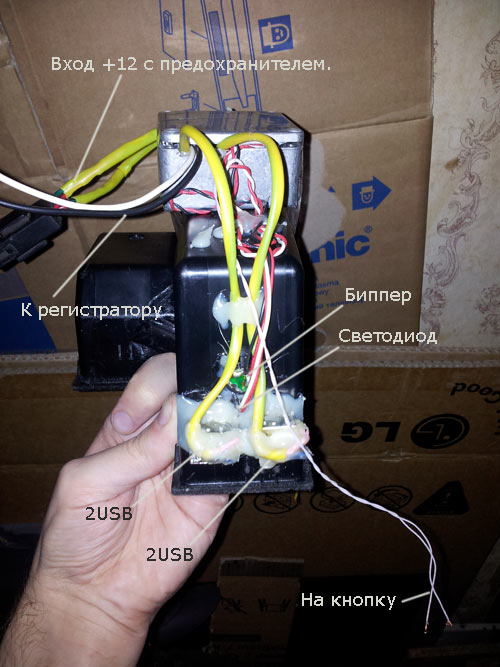
Schematically, it looks like this:
I made the payment under the existing box, did it with LUT.
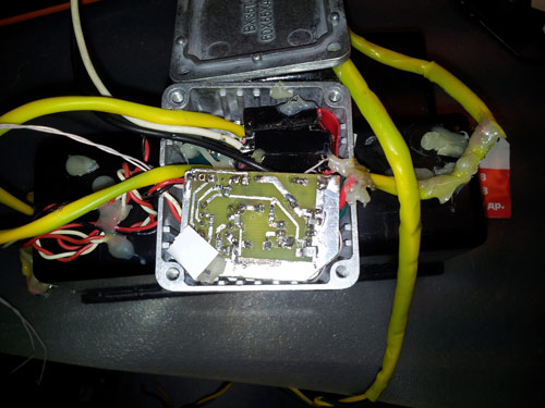
Blood guts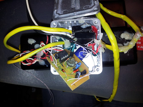
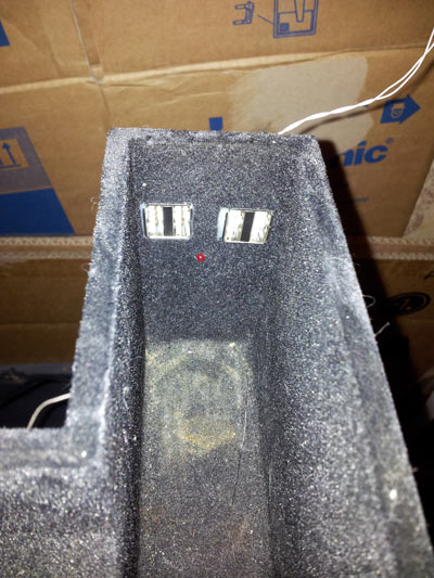
4 USB are well placed in the box, next to the LED was brought out and a hole was made (1mm) in order to better hear the beeper.
And the reverse side of the "medal". The aluminum box contains a control board and 2 converters. The box is taped to the bottom of the drawer, which is inserted into the armrest.
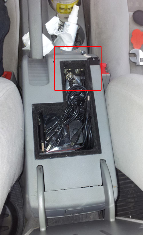
And in the car, everything looks culturally (the button is still not normally attached :).
On the mirror a little worse.

Power taken from the cigarette lighter, placed in the armrest. All connections on the connectors, so that the entire system can be easily pulled out and carried home for an upgrade.
Now I understand that it was possible to make everything more beautiful by taking thinner wires. Probably spring remake.
The archive with the scheme, the source code of the program, firmware, crafts, boards can be downloaded in ZIP .
PS Already two weeks was going to write this post, and only appeared a similar article motivated to start :)
Source: https://habr.com/ru/post/159121/
All Articles