Phased array antenna
On Habré already have an article on antennas. Continuing the topic, I want to tell the community about the principles of operation of phased antenna arrays (PAR). HEADLIGHTS have found widespread use in radar systems, missile defense, space communications; application in civilian objects (commercial) is complicated by the complexity of manufacture and high cost. Perhaps someone will be interested in the subject and come up with an effective use of HEADLIGHTS for commercial use.
HEADLIGHT is a group of emitters (phase shifters, EF), in which the relative phases of the signals vary in a complex manner, so that the effective emission of the HEADLIGHTS is amplified in the desired direction and suppressed in all others. LAMP is a matrix, where the element of the matrix is PV, but of course the PV in space can have other configurations. Figure 1 shows the radar sector survey "Ginger", is part of the anti-aircraft missile complex S300V. PAR and an irradiation mouthpiece can be seen.
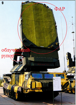
Picture 1.
There is a simple formula from the physics course: V = c / sqrt (mu * eps). In this formula, V is the phase velocity of the electromagnetic wave, c c is the speed of light in vacuum, mu is the magnetic permeability, eps is the dielectric constant. From this formula it can be seen that the phase velocity depends on mu and epsilon, and by changing these values we can introduce the delay of the EM wave through the PV. Therefore, PVs are ferrite (we can change their magnetic permeability) and ferroelectric (we can change their dielectric constant). Power is supplied to the phase shifters via the air path (as in Fig. 1) or by means of waveguides (for example, in small-sized anti-aircraft missile complexes, Fig. 2).
')

Figure 2. The Tor system.
Scheme PAR in fig. 4 [1]: The antenna is a line of emitters, and the PV is turned on between the power splitter and emitters. Ferrite PV is a cylindrical analog ferrite on which control windings are wound. Changing the current in the control windings (set by the PV control unit) changes the magnetic permeability and, accordingly, the phase velocity of the EM wave in the PV. Thus, sequentially changing the level of the control signal in the windings, the process of wavefront formation can be represented as shown in Figure 3, 4 (one-dimensional case). You can draw an analogy with the stones, which are consistently thrown into the water. Another analogy of the work of PAR can be a lens. Figure 5 shows the change in the wavefront shape with a lens [4].
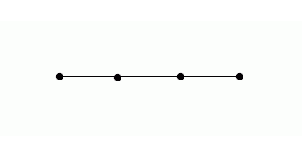
Figure 3. Wavefront formation.
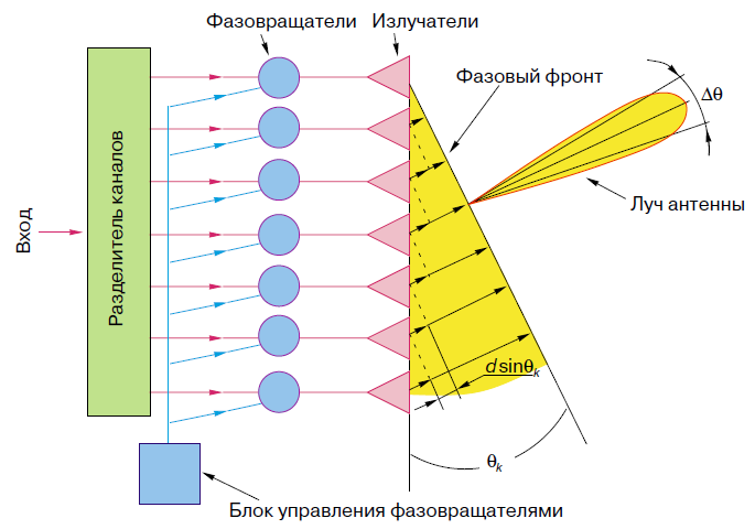
Figure 4. HEADLAMP.
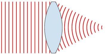
Figure 5.
The main beam is perpendicular to the phase front. From the radiation pattern (Fig. 6) it can be seen that, in addition to the main beam, there are backward and side lobes, which are parasitic and reducing their level is a matter of the distribution of the EM field in the lattice aperture. The change in the position of the beam in space occurs electrically (practically without inertia) —this quality is especially important.

Figure 6. Typical radiation pattern.
Electrical scanning provides the creation of a variety of phase shifts throughout the aperture and a significant rate of change of these shifts with relatively small power losses. The operation of phase shifters is controlled by a high-speed electronic system, which in the simplest cases controls groups of elements (for example, rows and columns in flat PHARs with a rectangular arrangement of emitters), and in the most complex - each phase shifter separately. The swing of a beam in space can be carried out both according to a predetermined law, and according to a program developed during the operation of the entire radio device, which includes the HEADLIGHT [2,3].
The drawings for the article can be found in the indicated literature, except for Figure 3. For a more detailed acquaintance with the HEADLIGHTS and their control, I can recommend the book by Samoylenko and Shishov, “Control of phased antenna arrays”.
1. O. G. Wendyk, “Phased array antenna - the eyes of a radio system”, 1997
2. en.wikipedia.org/wiki Phased antenna
3. en.wikipedia.org/wiki/Phased_array
4. ru.wikipedia.org/wiki/Linza
What is it?
HEADLIGHT is a group of emitters (phase shifters, EF), in which the relative phases of the signals vary in a complex manner, so that the effective emission of the HEADLIGHTS is amplified in the desired direction and suppressed in all others. LAMP is a matrix, where the element of the matrix is PV, but of course the PV in space can have other configurations. Figure 1 shows the radar sector survey "Ginger", is part of the anti-aircraft missile complex S300V. PAR and an irradiation mouthpiece can be seen.
Picture 1.
How is the phasing?
There is a simple formula from the physics course: V = c / sqrt (mu * eps). In this formula, V is the phase velocity of the electromagnetic wave, c c is the speed of light in vacuum, mu is the magnetic permeability, eps is the dielectric constant. From this formula it can be seen that the phase velocity depends on mu and epsilon, and by changing these values we can introduce the delay of the EM wave through the PV. Therefore, PVs are ferrite (we can change their magnetic permeability) and ferroelectric (we can change their dielectric constant). Power is supplied to the phase shifters via the air path (as in Fig. 1) or by means of waveguides (for example, in small-sized anti-aircraft missile complexes, Fig. 2).
')
Figure 2. The Tor system.
Scheme PAR in fig. 4 [1]: The antenna is a line of emitters, and the PV is turned on between the power splitter and emitters. Ferrite PV is a cylindrical analog ferrite on which control windings are wound. Changing the current in the control windings (set by the PV control unit) changes the magnetic permeability and, accordingly, the phase velocity of the EM wave in the PV. Thus, sequentially changing the level of the control signal in the windings, the process of wavefront formation can be represented as shown in Figure 3, 4 (one-dimensional case). You can draw an analogy with the stones, which are consistently thrown into the water. Another analogy of the work of PAR can be a lens. Figure 5 shows the change in the wavefront shape with a lens [4].
Figure 3. Wavefront formation.
Figure 4. HEADLAMP.
Figure 5.
The main beam is perpendicular to the phase front. From the radiation pattern (Fig. 6) it can be seen that, in addition to the main beam, there are backward and side lobes, which are parasitic and reducing their level is a matter of the distribution of the EM field in the lattice aperture. The change in the position of the beam in space occurs electrically (practically without inertia) —this quality is especially important.
Figure 6. Typical radiation pattern.
Electrical scanning provides the creation of a variety of phase shifts throughout the aperture and a significant rate of change of these shifts with relatively small power losses. The operation of phase shifters is controlled by a high-speed electronic system, which in the simplest cases controls groups of elements (for example, rows and columns in flat PHARs with a rectangular arrangement of emitters), and in the most complex - each phase shifter separately. The swing of a beam in space can be carried out both according to a predetermined law, and according to a program developed during the operation of the entire radio device, which includes the HEADLIGHT [2,3].
The drawings for the article can be found in the indicated literature, except for Figure 3. For a more detailed acquaintance with the HEADLIGHTS and their control, I can recommend the book by Samoylenko and Shishov, “Control of phased antenna arrays”.
Literature:
1. O. G. Wendyk, “Phased array antenna - the eyes of a radio system”, 1997
2. en.wikipedia.org/wiki Phased antenna
3. en.wikipedia.org/wiki/Phased_array
4. ru.wikipedia.org/wiki/Linza
Source: https://habr.com/ru/post/159109/
All Articles