Understanding shaders in Unity3D with a specific example
Some theory
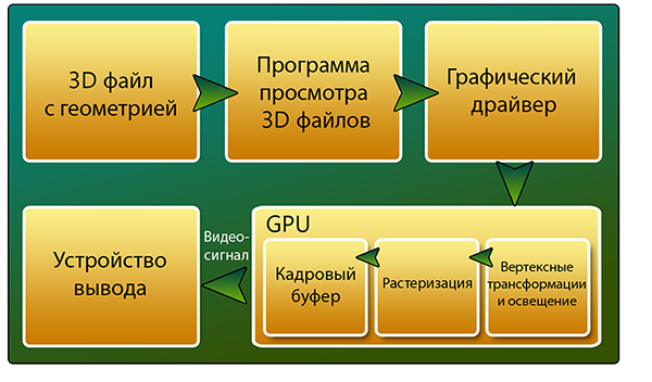
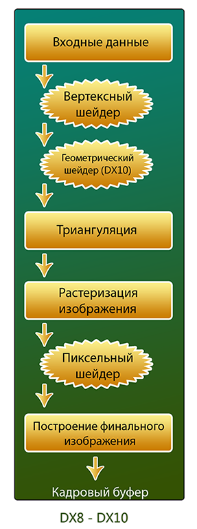
To understand the work of shaders, you need to be well aware of how the video card builds an image. The overall structure of the visualization of a 3D object on the screen is shown in the figure below:
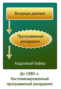
To begin with, let's look at a concept like Graphics Rendering Pipeline. This is a pipeline, the stages of which are the video card for constructing the final image. Let's delve a bit into history. The first computers used software rendering. The central processor was engaged in all miscalculations. And the conveyor looked like this:
The very first 3D accelerators used the so-called Fixed-Function Pipeline. From the name it follows that it was fixed and strictly consistent. To intervene in the construction of the picture was impossible. Now we will consider all the stages of this pipeline. In the future, it will be useful to us.
- Input data. As input parameters, the video card receives the object as separate vertices with multiple attributes. For example, the position of the vertex in space, its color, normal, texture coordinates and others.
- Transformation and lighting. At this stage, geometric operations are performed on the object (displacement, rotation, scale). Here is the calculation of the scene illumination. For each vertex, the illuminance values are calculated based on the location and type of light sources, as well as the parameters characterizing the object surface (reflections, absorption).
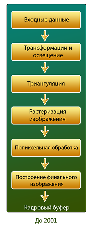
- Triangulation. At this stage, the vertices are combined into triangles.
- Rasterization The purpose of this stage is to calculate the color of the pixels based on the data that has already been prepared. Since we only have information about the color of the vertices, to obtain the color of the pixel, we interpolate linearly the value between the color values of the corresponding vertices.
- Pixel processing. At this stage there is a coloring of pixels. Input data are the previous level data. Also here we can apply additional effects to the pixels. For example texturing.
- Formation of the finished image. Now we have to build the final frame. At this stage, Z-buffer data is taken into account in order to determine which object is closer to the camera. Also here is an alpha test. Layer by layer objects are “plotted” on the final image. Also post effects can be applied here. After that, the finished frame is placed in the Frame Buffer.
So, we reviewed the stages of Fixed-Function Pipeline. As we see, we can only influence the final image by selecting certain options at certain stages, but we cannot write, for example, our lighting model. In those days, you had to be content with supporting a particular video adapter. That was before the appearance of the first video cards with hardware support for DirectX 8.0 - 8.1. From this point on, it was possible to write programs for processing vertices and pixels. The conveyor for such a model is shown in the figure below.
')
In the future, it is planned to make all stages of the pipeline programmable.
Now, knowing how a video card builds an image, it’s worth talking a bit about 3D objects. A model is a collection of vertices, connections between them, as well as materials, animations, etc. Vertices have attributes. For example, UV coordinates. They show where this vertex is located on the texture scan. The material determines the appearance of the object and includes a reference to the shader used to visualize the geometry or particles. Thus, these components will not be displayed without material.
A shader is a program for one of the stages of the graphics pipeline. All shaders can be divided into two groups: vertex and fragmentary (pixel). Unity3D has a simplified approach to writing shaders - Surface Shader. This is just a higher level of abstraction. When compiling the Surface shader, the compiler will create a shader consisting of vertex and pixel. Unity3D has its own language. Called ShaderLab . It supports inserts on CG and HLSL.
Practice
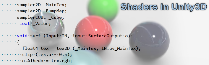
As an example, consider writing a shader that imposes a texture, a normal map, a reflection map (based on Cubemap) on the diffuse object, and cuts pixels along the alpha channel in the diffuse texture.
To begin, consider the general syntax of ShaderLab. Even if we write a shader in CG or HLSL, we still need to know the ShaderLab syntax, so that we can set the parameters of our shader in the inspector.
Shader "Group/SomeShader" { // properties that will be seen in the inspector Properties { _Color ("Main Color", Color) = (1,0.5,0.5,1) } // define one subshader SubShader { Pass { } } } Fallback "Diffuse" } The first keyword is the shader . After it in quotes the name of the shader is indicated. Moreover, you can specify via '/' the path where the shader will be located in the drop-down menu when setting up the material in the editor. After that there is a description of the Properties {} parameters, which will be visible in the inspector and with which the user can interact.
Each shader in Unity3D contains at least one Subshader in its body. When it is necessary to display the geometry, the engine searches for the necessary shader and uses the first Subshader from the list that the video card can process. This is done to ensure that the same shader can be correctly displayed on various video cards that support different shader models. The Pass {} keyword defines a block of instructions for a single pass. A shader can contain from one to several passes. The use of several passes can be useful, for example, in the case of optimization of shaders for old hardware or to achieve special effects (outline, toon shading, etc.).
If Unity3D in the body of the shader has not found a single SubShader'a, which can correctly display the geometry, use a rollback to another shader, announced after the Fallback instruction. In the example above, the Diffuse shader will be used if the video card cannot correctly display the current one.
Now consider a specific example.
Shader "Example/Bumped Reflection Clip" { Properties { _MainTex ("Texture", 2D) = "white" {} _BumpMap ("Bumpmap", 2D) = "bump" {} _Cube ("Cubemap", CUBE) = "" {} _Value ("Reflection Power", Range(0,1)) = 0.5 } SubShader { Tags { "RenderType" = "Opaque" } Cull Off CGPROGRAM #pragma surface surf Lambert struct Input { float2 uv_MainTex; float2 uv_BumpMap; float3 worldRefl; INTERNAL_DATA }; sampler2D _MainTex; sampler2D _BumpMap; samplerCUBE _Cube; float _Value; void surf (Input IN, inout SurfaceOutput o) { float4 tex = tex2D (_MainTex, IN.uv_MainTex); clip (tex.a - 0.5); o.Albedo = tex.rgb; o.Normal = UnpackNormal (tex2D (_BumpMap, IN.uv_BumpMap)); float4 refl = texCUBE (_Cube, WorldReflectionVector (IN, o.Normal)); o.Emission = refl.rgb * _Value * refl.a; } ENDCG } Fallback "Diffuse" } The Properties field contains four variables that will be displayed in the Unity3D inspector.
_MainTex - the name displayed in the inspector, the type and the default value are indicated in brackets.
_MainTex and _BumpMap are textures, _Cube is a cube for reflections, _Value is a slider for the degree of reflection effect.
The tag {"RenderType" = "Opaque"} marks the shader as opaque. This affects the draw queue.
Cull Off indicates that there will be no clipping in the normal directions in the shader. There are three options for clipping polygons: the normals of which are directed from the camera, into the camera, and without clipping. The last option means that we will see the polygon from two sides.
When writing code, we will use the CG insert. The insert is framed by two keywords: CGPROGRAM , ENDCG .
#pragma surface surf Lambert - announcement of the surface-shader function and additional parameters. In this case, the function is called surf , and the Lambert lighting model is indicated as additional parameters.
Now consider the input structure. All possible variables of the input structure can be found in the help . We will consider only those that used.
The variables uv_MainTex and uv_BumpMap are the UV coordinates needed by the shader for the correct texture mapping on the object. These variables must be named the same as the names of the texture variables with the prefix uv_ or uv2_ for the first and second channels, respectively. worldRefl and INTERNAL_DATA are used for reflections.
Now consider the function of the surf shader.
The first step is a four-component vector that stores information about the color of a pixel texture. The tex variable will store information about it. After that, with the clip function, we specify which pixels we skip when rendering. Since we cut off according to the information stored in the alpha channel, then in the parameters specify tex.a.
After clipping, we apply our main texture to the object with the following line:
o.Albedo = tex.rgb; The variable o is our output structure. All its fields can be viewed in the SurfaceShaders help.The next step is to use the normal map:
o.Normal = UnpackNormal (tex2D (_BumpMap, IN.uv_BumpMap)); Then we make the imposition of reflection: float4 refl = texCUBE (_Cube, WorldReflectionVector (IN, o.Normal)); o.Emission = refl.rgb * _Value * refl.a; It is worth noting here that we multiply the received information about the reflection by _Value so that we can control the degree of effect in the inspector.Well, in the end we do not forget to add the Fallback in case the video card cannot display this shader correctly.
And here's what we got:
Source: https://habr.com/ru/post/158983/
All Articles