Understanding MSP430 and Toilet Automation
I have been reading the DIY rubric for a long time and my hands itched to do something on the microcontroller. And read at random about the MSP430 Launch Pad from Texas Instruments for $ 4.30. Perfect set to start.
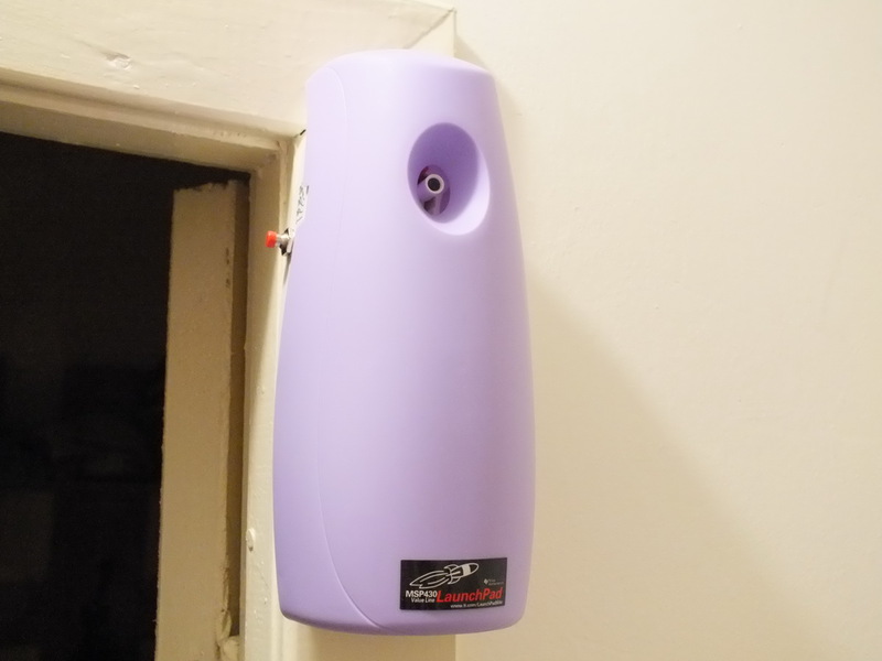
An automatic air freshener of one famous brand was chosen as an object for experiments.
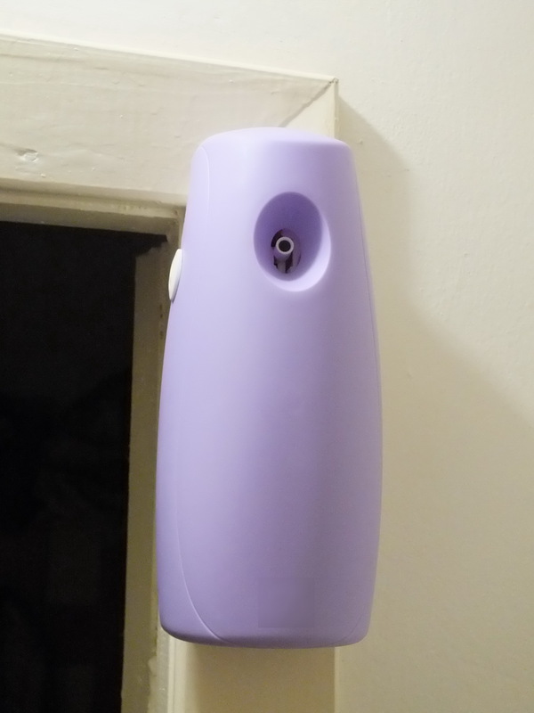
The original freshener has the function of spraying at specified intervals, which is not always convenient. Since no one is at home in the afternoon, the balloon is wasted. In addition, the developers have built in "protection" against the use of cylinders from other manufacturers, which, although it is quite simple, but life becomes easier without it. In addition, for "manual" spraying had to get the bottle and use it as a regular freshener.
First, to make the algorithm more intelligent. Namely, to make it so that the freshener works after visiting the toilet. And secondly, add the function of "manual" operation without opening the case.
I decided to automate the triggering of the sprayer on the basis of a light sensor. That is, when you turn off the light after 5 seconds should work spray. After that, do not respond to the on-off light for 15 minutes. In order not to "re-refresh" the room so it will not be possible to breathe. Just add a button for "manual" spraying regardless of the mode of operation.
')
Before adding something new, I decided to see what was inside this “miracle unit”.

And the first thing I came across was screws with a non-standard "triangular" head:
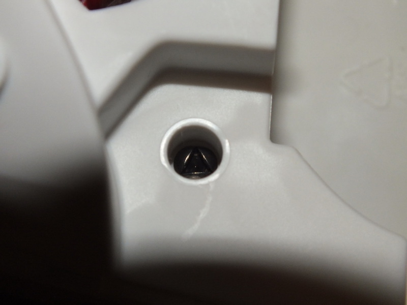
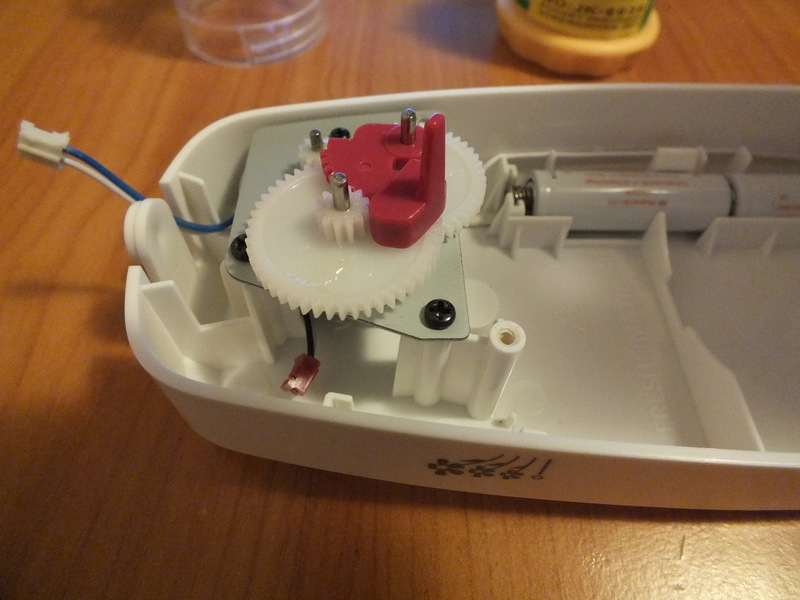
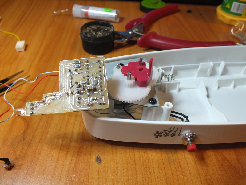
Fortunately, a suitable screwdriver was found in the micro screwdriver set and the process did not stop there. Inside, everything was very simple. The mechanism of the descent is an ordinary electric motor through a gearbox from a pair of gears connected to the tongue, which presses on the balloon sprayer. The control board is of no interest, only as a template for making one's own, and as a source of connectors for connecting the power and the descending motor.
When it became clear what this device is, you can begin to design your own control module. The brain will be a microcontroller MSP430G2553. There is a younger G2452 in the LaunchPad set and you can use it, but I chose the older one, since it has a hardware UART, which is convenient for debugging and calibration. For example, the indicator of an empty cylinder. Initially, it is not known how many sprays it will be enough, so the program has a counter with a record in non-volatile memory, followed by reading and sending over the UART (for this you have to remove the controller from the control module and put it on the debug board). After receiving these data and bringing the program to the final version, I plan to replace the controller with a younger model.
The scheme of the control module. I want to immediately notice, this is my first finished device, so the circuit and the board are far from the quality standards:

The scheme was based on the recommendations of the Datasheet controller and articles from the Internet. Special thanks DIHALT his textbook on electronics for beginners became for me a starting point.
The components are very simple. The filter on the capacitors C1 and C2, according to the recommendations of the Datasheet, increases the accuracy of the ADC. The photoresistor LDR1 is a light sensor and is connected via a voltage divider on resistor R3. The motor descent is controlled through a transistor BC337. Also on the diagram, the manual release button S1 and the LEDs of two colors are added. I used a two-color LED. It blinks green once a second as an indicator of normal operation, and when the battery is below 2.5V, it starts flashing red. The source of the real-time clock signal is Quartz Z1 at 32768 Hz, which comes bundled with the board and controllers.
I wrote the program for the controller in IAR Embedded Workbench in C ++. I cite here her code with comments.
After compiling and debugging the program on the board, the module was assembled for tests on the breadboard:

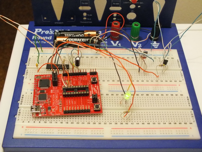
The LaunchPad debug card here is simply a holder for quartz, since it is so small that it is simply impossible to place it on the layout.
When I was convinced that everything works without failures and according to the algorithm, I started making the board for the control module, which can be placed in the case in place of the native one.
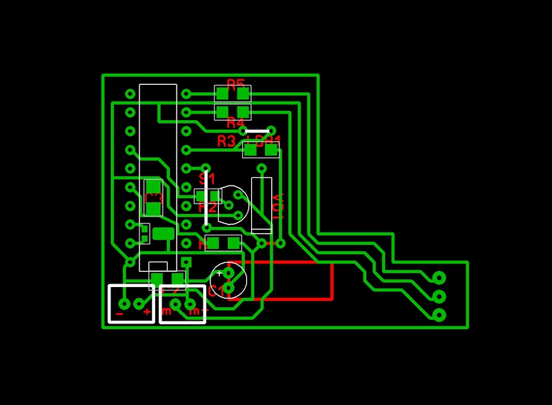
Layout of the board for the control module (done in Sprint-Layout):
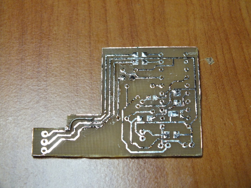
Then the board was made. The drawing was done using the LUT method (thanks again DIHALT ), then the board was etched in ferric chloride and tinned.
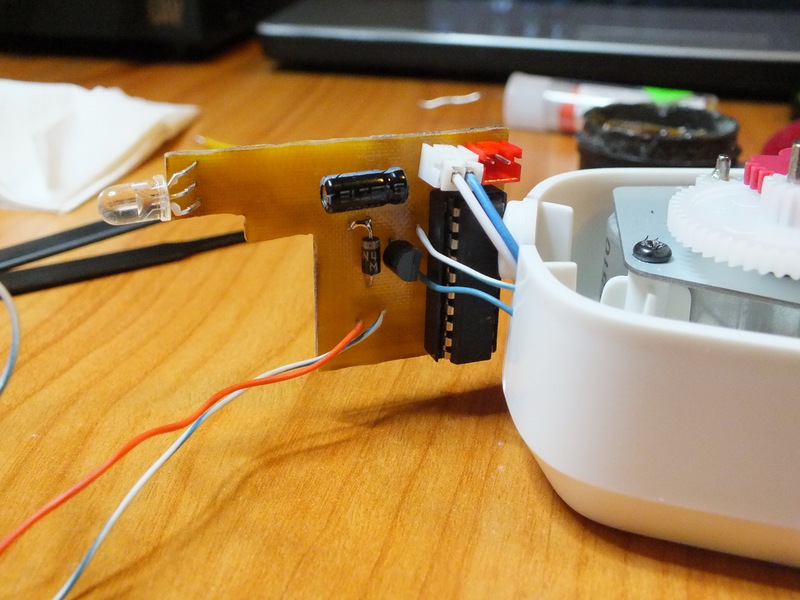
Next, solder the components. The microcontroller is placed in the panel so that it is easy to remove it and read the value of the counter, as well as change to another one when finalizing the program.

And then after testing the device is already assembled with a new control module.
As a result of work on this device, which lasted about a week in the evenings, I was convinced that the development of devices on modern microcontrollers presents no difficulties even for beginners to comprehend electronics. The fact that everything worked as planned, further inflamed enthusiasm. And the pleasure of something made with their own hands from and to was received considerable.
And I emphasize once again that before this, I had almost no experience in programming microcontrollers, or experience in working with electronics. Therefore, most likely I have made mistakes, both in software and in hardware, for which I ask you not to judge strictly.
Thanks for attention.
An automatic air freshener of one famous brand was chosen as an object for experiments.
Task
The original freshener has the function of spraying at specified intervals, which is not always convenient. Since no one is at home in the afternoon, the balloon is wasted. In addition, the developers have built in "protection" against the use of cylinders from other manufacturers, which, although it is quite simple, but life becomes easier without it. In addition, for "manual" spraying had to get the bottle and use it as a regular freshener.
What did you want to get
First, to make the algorithm more intelligent. Namely, to make it so that the freshener works after visiting the toilet. And secondly, add the function of "manual" operation without opening the case.
Decision
Algorithm
I decided to automate the triggering of the sprayer on the basis of a light sensor. That is, when you turn off the light after 5 seconds should work spray. After that, do not respond to the on-off light for 15 minutes. In order not to "re-refresh" the room so it will not be possible to breathe. Just add a button for "manual" spraying regardless of the mode of operation.
')
Opening the "patient"
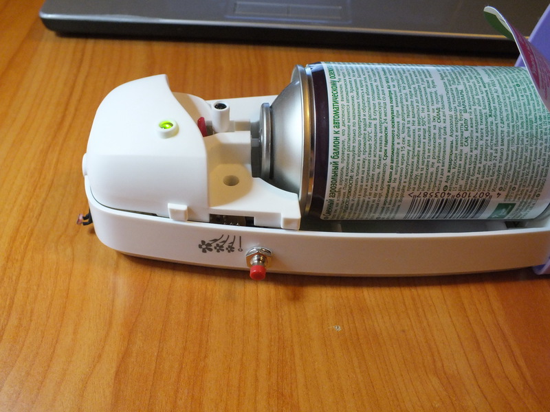
Before adding something new, I decided to see what was inside this “miracle unit”.
And the first thing I came across was screws with a non-standard "triangular" head:
Fortunately, a suitable screwdriver was found in the micro screwdriver set and the process did not stop there. Inside, everything was very simple. The mechanism of the descent is an ordinary electric motor through a gearbox from a pair of gears connected to the tongue, which presses on the balloon sprayer. The control board is of no interest, only as a template for making one's own, and as a source of connectors for connecting the power and the descending motor.
Electronic part
When it became clear what this device is, you can begin to design your own control module. The brain will be a microcontroller MSP430G2553. There is a younger G2452 in the LaunchPad set and you can use it, but I chose the older one, since it has a hardware UART, which is convenient for debugging and calibration. For example, the indicator of an empty cylinder. Initially, it is not known how many sprays it will be enough, so the program has a counter with a record in non-volatile memory, followed by reading and sending over the UART (for this you have to remove the controller from the control module and put it on the debug board). After receiving these data and bringing the program to the final version, I plan to replace the controller with a younger model.
The scheme of the control module. I want to immediately notice, this is my first finished device, so the circuit and the board are far from the quality standards:
The scheme was based on the recommendations of the Datasheet controller and articles from the Internet. Special thanks DIHALT his textbook on electronics for beginners became for me a starting point.
The components are very simple. The filter on the capacitors C1 and C2, according to the recommendations of the Datasheet, increases the accuracy of the ADC. The photoresistor LDR1 is a light sensor and is connected via a voltage divider on resistor R3. The motor descent is controlled through a transistor BC337. Also on the diagram, the manual release button S1 and the LEDs of two colors are added. I used a two-color LED. It blinks green once a second as an indicator of normal operation, and when the battery is below 2.5V, it starts flashing red. The source of the real-time clock signal is Quartz Z1 at 32768 Hz, which comes bundled with the board and controllers.
Software part
I wrote the program for the controller in IAR Embedded Workbench in C ++. I cite here her code with comments.
Spary file code spary.h
Header file spray.h
#ifndef __SPRAY_H_ #define __SPRAY_H_ #include <sstream> // #define BUTTON BIT4; // #define SPRAY_PORT BIT6;// P1.6 #define LED_GREEN BIT1; // P2.1 #define LED_RED BIT2; // P2.2 #define LIGHT_SENSOR INCH_5; // A5 #define DARK_VALUE 650; // " ." #define LOWBATT_VALUE 520; // . // unsigned int SleepPeriod = 900; // . 15 . (900) unsigned int SpayDelay = 5; // 5. unsigned int DarkValue = 650; // " ." unsigned int LowBattValue = 520; // . unsigned int BattInterval = 5; // 5. // unsigned int ADCValue; // unsigned int SprayCount; // unsigned int TimerCount = 0; // unsigned int BattTimer = 0; // unsigned int RXByte; // UART // bool ADCDone = false; // bool LightOn = false; // ( ) bool SleepMode = false; // ( 15 ) bool IsCounting = false; // , // bool LowBatt = false; // bool BlinkOn = false; // bool Tick = false; // bool IsADCOn = false; // bool IsADCLight = true; // (true - // , false - ) bool ForceSpay = false; // bool UARTReceived = false; // UART // void UARTSend(string str); // UART void LightSensorOn(); // void VCCSensorOn(); // unsigned int ReadCountFromFlash(); // void WriteCountToFlash(unsigned int); // void Spray(); // #endif Program code
The text of the program. main.cpp:
The program in this form does not contain a block to indicate the end of the cylinder, since at the time of writing it is not known how many sprays it will be enough.
#include <msp430g2553.h> #include "spray.h" int main( void ) { // WDT WDTCTL = WDTPW + WDTHOLD; // //------------------------- // - P1DIR &= ~BUTTON; // P1REN |= BUTTON; // P1OUT &= ~BUTTON; // - GND P1IES |= BUTTON; // P1IFG &= ~BUTTON; // P1IE |= BUTTON; // P1DIR |= SPRAY_PORT; // P1OUT &= ~SPRAY_PORT; // // P2DIR |= LED_GREEN P2DIR |= LED_RED; // ( ) P2OUT |= LED_GREEN; P2OUT &= ~LED_RED; // . //------------------------- // DCOCTL = CALDCO_1MHZ; // ~ 1 BCSCTL1 = CALBC1_1MHZ; //------------------------- // TACTL = TASSEL_1 + MC_1; // ACLK (), // CCR0 CCR0 = 0x8000; // .. 32768, // CCTL0 = CCIS0 + OUTMOD0 + CCIE; // , // //------------------------- // UART. FLASH P1SEL = BIT1 + BIT2; // P1SEL2 = BIT1 + BIT2; // UART UCA0CTL1 |= UCSSEL_2; // - SMCLK ~ 1MHz UCA0BR0 = 0x68; // 9600 UCA0BR1 = 0; // 1000000 / 9600 = 104 = 0x68 UCA0MCTL = UCBRS0; UCA0CTL1 &= ~UCSWRST; // IE2 = UCA0RXIE; // UART //------------------------- // Flash FCTL2 = FWKEY + FSSEL1 + FN1; // // . 65535 - // SprayCount = ReadCountFromFlash(); if(SprayCount == 65535) { SprayCount = 0; // WriteCountToFlash(SprayCount); // 0 Flash } //------------------------- __delay_cycles(2000); // //------------------------- __bis_SR_register(GIE); // P2OUT &= ~LED_GREEN; // . . UARTSend("Ready\r\n"); // while(true) { if(Tick) // . { Tick = false; // BattTimer++; if(BattTimer >= BattInterval) // { BattTimer = 0; // VCCSensorOn(); // } if(!SleepMode) // { LightSensorOn(); // if(IsCounting) // { if(TimerCount >= SpayDelay) // { Spray(); // } } } else { // if(TimerCount >= SleepPeriod) { TimerCount = 0; // SleepMode = false; // } } } if(ADCDone) // { ADCDone = false; // if(IsADCLight) // { if(ADCValue < DarkValue) // . { LightOn = true; // " " IsCounting = false; // ( , ) TimerCount = 0; // } else // { if(LightOn) // { LightOn = false; // IsCounting = true; // TimerCount = 0; } } } else // { if(ADCValue < LowBattValue) { LowBatt = true; // } else { LowBatt = false; // - } } } if(ForceSpay) // . . { ForceSpay = false; Spray(); } if(UARTReceived) // UART. . { UARTReceived = false; ostringstream s; s << SprayCount << "\r\n"; UARTSend(s.str()); } } } // UART void UARTSend(string str) { int len = str.length(); for(int i=0;i<len;i++) { while(!(IFG2&UCA0TXIFG)); UCA0TXBUF = str[i]; } } // void LightSensorOn() { if(!IsADCOn) { IsADCOn = true; IsADCLight = true; ADC10CTL0 &= ~ENC; ADC10CTL0 = ADC10SHT_3 + ADC10ON + ADC10IE; ADC10CTL1 = ADC10SSEL_2 + LIGHT_SENSOR; ADC10CTL0 |= ENC + ADC10SC; } } // void VCCSensorOn() { if(!IsADCOn) { IsADCOn = true; IsADCLight = false; ADC10CTL0 &= ~ENC; ADC10CTL0 = SREF_1 + ADC10SHT_3 + REFON + ADC10ON + REF2_5V + ADC10IE; ADC10CTL1 = ADC10SSEL_2 + INCH_11; __delay_cycles(128); ADC10CTL0 |= ENC + ADC10SC; } } // unsigned int ReadCountFromFlash() { __bic_SR_register(GIE); // int *Flash_ptr; Flash_ptr = (int *) 0x1040; // *Flash_ptr = 0; // unsigned int value = *Flash_ptr; // __bis_SR_register(GIE); // return value; // } // void WriteCountToFlash(unsigned int value) { __bic_SR_register(GIE); // int *Flash_ptr; Flash_ptr = (int *) 0x1040; // FCTL1 = FWKEY + ERASE; // FCTL3 = FWKEY; *Flash_ptr = 0; // FCTL1 = FWKEY + WRT; *Flash_ptr++ = value; // Flash FCTL1 = FWKEY; FCTL3 = FWKEY + LOCK; // __bis_SR_register(GIE); // } // void Spray() { __bic_SR_register(GIE); // P1OUT |= SPRAY_PORT; // __delay_cycles(500000); // ~ 0.5 ( 1) P1OUT &= ~SPRAY_PORT; // // LightOn=false; SleepMode=true; IsCounting=false; TimerCount=0; SprayCount++; WriteCountToFlash(SprayCount); __bis_SR_register(GIE); // } //--------------------------- // // #pragma vector=ADC10_VECTOR __interrupt void ADC_Handler() { ADCValue = ADC10MEM; // ADCDone = true; // IsADCOn = false; } // #pragma vector=PORT1_VECTOR __interrupt void Button_Handler() { P1IE &= ~BUTTON; // P1IFG &= ~BUTTON; // ForceSpay = true; // // __delay_cycles(300000); P1IE |= BUTTON; // } // 1 . #pragma vector=TIMER0_A0_VECTOR __interrupt void Timer_Handler() { // if(!BlinkOn) // { // // - , if(LowBatt) { P2OUT |= LED_RED; } else { P2OUT |= LED_GREEN; } BlinkOn = true; } else // { P2OUT &= ~LED_RED; P2OUT &= ~LED_GREEN; BlinkOn = false; } TimerCount++; // Tick=true; // } // UART #pragma vector=USCIAB0RX_VECTOR __interrupt void UART_Handler() { RXByte = UCA0RXBUF; UARTReceived = true; } The program in this form does not contain a block to indicate the end of the cylinder, since at the time of writing it is not known how many sprays it will be enough.
Assembly
After compiling and debugging the program on the board, the module was assembled for tests on the breadboard:
The LaunchPad debug card here is simply a holder for quartz, since it is so small that it is simply impossible to place it on the layout.
When I was convinced that everything works without failures and according to the algorithm, I started making the board for the control module, which can be placed in the case in place of the native one.
Layout of the board for the control module (done in Sprint-Layout):
Then the board was made. The drawing was done using the LUT method (thanks again DIHALT ), then the board was etched in ferric chloride and tinned.
Next, solder the components. The microcontroller is placed in the panel so that it is easy to remove it and read the value of the counter, as well as change to another one when finalizing the program.
And then after testing the device is already assembled with a new control module.
Conclusion
As a result of work on this device, which lasted about a week in the evenings, I was convinced that the development of devices on modern microcontrollers presents no difficulties even for beginners to comprehend electronics. The fact that everything worked as planned, further inflamed enthusiasm. And the pleasure of something made with their own hands from and to was received considerable.
And I emphasize once again that before this, I had almost no experience in programming microcontrollers, or experience in working with electronics. Therefore, most likely I have made mistakes, both in software and in hardware, for which I ask you not to judge strictly.
Thanks for attention.
Source: https://habr.com/ru/post/158965/
All Articles