Smart home, as I sunk to such. Part 1
A couple of years ago, when there was a question of finishing a new apartment, a seemingly trivial task arose.
Given:
- Kitchen-studio (kitchen combined with a hall / corridor), three points of lighting.
- It is necessary to control the lighting from two points. At the entrance to the apartment and the kitchen.
Solution options:
- We buy the so-called walk-through switches, put three pieces in the kitchen, three in the hallway - this is happiness. It just happened that you need to drive 9 cable wires from the corridor to the kitchen, ugly, there is no place to hide.
- We buy ready-made solutions for managing one source from several points.
I don’t remember the exact numbers, but it turned out to be about 10000r for a lighting point + 1000r for each switch, for a total of 36000r. Toad. - Oddly enough, but this idea was expressed by the wife, in general, far from IT: “Do you remember, you did a traffic light in Yandex ? Maybe here, too, something you figure it out? ”
In fact, why not, I thought?
But I am not an electronics engineer, I am a programmer, I never programmed controllers, only full-fledged servers. So the brain must be a server. And once the server is set up, then controlling three light bulbs is from a cannon on sparrows (even a nuclear charge on flies). So you can still add functions.
Then Ostap suffered (s), the capital moves to Vasyuki. Three bulbs with switches turn into a control, monitoring, video surveillance system, etc.
I will not talk about how I chose 1-wire for a long time, they wrote a lot about it before me.
Bribed:
- Low price
- Availability
- Thermal sensors from one chip on parasitic power
- Ease of installation
- Sufficient speed (compared to X10)
- Open standard
I’ll say right away that I wasn’t going to solder the chips myself, I wanted to buy ready-made and adapt for myself.
But at that time I worked together with BarsMonster and he “put me on the right path”.
When I needed to control 8 sources in one place (a ceiling with LED lights), I could buy four controllers (each with two points could control) 700 rubles already suffocating 700 rubles.
And he suggested: "Let me make you a scheme, because everything is simple there." “Come on,” I said.
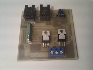
Somewhere in a week I received a fee and a set of components (I decided to solder myself, it was interesting). I did, I liked it. Then he himself spread the next board, BarsMonster only erased it, and then he mastered the process of manufacturing printed circuit boards at home and made the following boards himself.
')
Computer layout -> laser printer -> iron -> ferric chloride -> soldering iron. Voila!
The first schemes were similar to those purchased, on a DS2413 chip, providing control of two sources. But then I almost completely switched to DS2408, which gives eight channels. But how to use them (to control or read the sensor) was decided in each case. And of course everyone’s favorite DS18B20 thermometer.
At the moment I have used:
- Ten DS18B20
- Four boards on DS2413
- Five boards on DS2408
- One purchase fee for humidity and light control with 1-wire interface
With the DS18B20, everything is quite simple, I connected two legs to the bus and forgot.
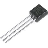
Although, then it turned out the pitfalls. On the parasitic power supply, the sensor blocks the entire bus for the time of temperature measurement, and the more accurate the measurement, the longer (from 0.3 to 1.5 seconds), which turned out to be critical for polling the sensors responsible for the switches. So, if I did everything from scratch, I would either make power boards for them, or even throw a separate bus at all; there’s no point in asking them themselves more often than once every few minutes.
Why so much? But because it is easy to put;)
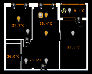
- Temperature monitoring in each room, kitchen, bathroom and loggia
- Two sensors on the street (one near the house, but it can heat up from the house, the second on the spoke a meter away from the house, it can heat up from the sun, I take the final temperature as the minimum)
- Monitoring floor temperature
- Monitoring the temperature of the floor heating board (the floor power is about 700W and the board is significantly heated)
- Monitoring the server temperature (server of the smart home control, video surveillance, and backup server along the way) bricked up
- Monitoring the temperature of the shield with routers (closed space, a lot of warming electronics)
DS2413 boards

I bought the first three boards, then I made two:
- Corridor lighting (two light sources)
- Temporary lighting in the future bedroom (repair is not finished)
- Manage warm floors (had to put a radiator on the triac)
- Ventilation shutter control
- Control of ventilation pump and lighting on the loggia
DS2408 Boards
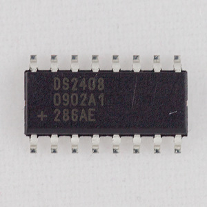
The first DS2408 board was used to control all the lighting in the kitchen, since the house is smart, it is no longer interesting to be limited to three sources of lighting, as originally planned. Eight channels? Let there be eight sources. At the moment, four and four are connected in the project (repair is not finished yet).
The second board was entirely for reading sensors. Namely, opening sensors on all windows and the door to the loggia. All the windows face one side of the house, the board is marked out on the loggias, and on the outer wall stretched wires to all the windows. Moreover, at the beginning I thought to pull the wire to each one separately, and then I found a more elegant solution. Twisted pair, from which one pair is gradually moving away to the sensor.
The third board is also entirely for sensors, but on the front door:
- Motion sensor in the common corridor (to turn on the video camera and record all passing by).
- Middle motion sensor that responds only if you come close to the door. (Why do we need a doorbell? You can understand that someone has come.)
- Sensor on the front door.
- Separate sensor on the heck and each of the locks.
As opening sensors, I used unmarked Soviet reed switches dug in the bins of my father-in-law. Plus Neodymium magnets 1x10 mm
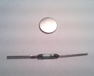
The sensors on the locks are similar, only I placed the reed switches themselves inside the door frame, and glued the magnets to the bolts of the locks.
Thus, almost all sensors turned out to be hidden.
In the following two boards for DS2408, for the nursery and the bathroom, I made two channels for controlling the lighting, the rest for the sensors:
- Main and peripheral lighting
- Switches (at the beginning it seemed that it was not always convenient for children to click on the touch panel)
- Motion Sensor
- Door sensor
- Two backup channels
In the backup channels, in the future, I want a story in the bathroom leakage sensors, and in the children's smoke sensor.
By making the latest boards on the DS2408, I, trying to save space, made one mistake that complicates installation and maintenance. I brought to the terminals one contact 5V, 12V, GND. I had to connect several wires to one (for example, the reed switch is connected between 5V and the input contact, the same with the motion sensor, but it still needs 12V and GND), which is inconvenient and unreliable.
With the iron finished, on the software part, I will stop in more detail the next time, but looking ahead, it turned out like this:
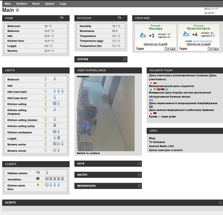
Web:
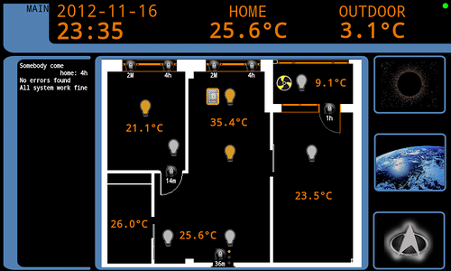
Touch screen:
UP:
Continued here
Smart home, as I sunk to such. Part 2
Smart home, as I sunk to such. Part 3
Source: https://habr.com/ru/post/158911/
All Articles