Ethernet physics for the smallest
- What is a collision domain?
- How many pairs are used for ethernet and why?
- For what pairs is the reception, and for what transfer?
- What limits the length of a network segment?
- Why the frame can not be less than a certain size?
If you do not know the answers to these questions, and read the standards and serious literature on the topic of laziness - I ask under the cat.
Some people think that these are obvious things, others will say that it is a boring and unnecessary theory. Nevertheless, such questions can be heard from time to time at the interviews. My opinion: about what will be discussed below, you need to know everyone who has to take the 8P8C “crimp” (this connector is usually mistakenly called RJ-45 ). I do not pretend to academic depth, I will refrain from formulas and tables, just leave the linear coding behind. It will be mainly about copper wires, not about optics, because they are more common in everyday life.
')
Ethernet technology describes the two lower layers of the OSI model at once. Physical and channel. We will continue to talk only about the physical, i.e. about how bits are transmitted between two adjacent devices.
Ethernet technology is part of the rich heritage of the Xerox PARC research center. Early versions of Ethernet used coaxial cable as a transmission medium, but over time it was completely supplanted by fiber and twisted pair. However, it is important to understand that the use of coaxial cable largely determined the principles of operation of Ethernet. The fact is that coaxial cable is a shared transmission medium. An important feature of a shared environment: several interfaces can use it at the same time, but only one should transmit at a time. Using a coaxial cable, you can connect not only 2 computers to each other, but more than two, without the use of active equipment. This topology is called a tire . However, if at least two nodes on the same bus start simultaneously transmitting information, their signals will overlap and the receivers of the other nodes will not understand anything. This situation is called a collision , and the part of the network whose nodes compete for the common transmission medium is the collision domain . In order to recognize a collision, the transmitting node constantly monitors the signals in the medium and if the own transmitted signal differs from the observed one, the collision is fixed. In this case, all nodes cease to transmit and resume transmission after a random period of time.
Conflict Domain Diameter and Minimum Frame Size
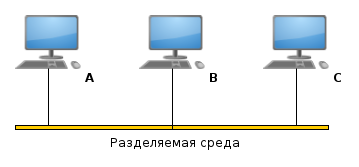
Now let's imagine what will happen if, in the network shown in the figure, nodes A and C simultaneously begin to transmit, but will have time to finish it before they receive each other's signal. This is possible with a fairly short transmitted message and a sufficiently long cable, because, as we know from the school curriculum, the propagation speed of any signals is C = 3 * 10 8 m / s at best. Since each of the transmitting nodes will receive a counter signal only after it has already finished transmitting its message - the fact that a collision has occurred will not be established by any of them, and therefore there will be no retransmission of frames. But the node B at the input will receive the sum of the signals and will not be able to correctly accept any of them. In order for this situation to happen, it is necessary to limit the size of the collision domain and the minimum frame size. It is not difficult to guess that these values are directly proportional to each other. If the amount of information transmitted does not reach the minimum frame, it is increased by the special pad field, the name of which can be translated as a placeholder.
Thus, the larger the potential size of a network segment, the more overhead is spent on transferring portions of data of small size. Ethernet technology developers had to look for a middle ground between these two parameters, and the minimum frame size was set to 64 bytes.
Twisted pair and full duplex mode
 Twisted pair as a transmission medium differs from coaxial cable in that it can connect only two nodes and uses separate media to transfer information in different directions. One pair is used for transmission (1.2 contacts, usually orange and white-orange wires) and one pair for receiving (3.6 contacts, usually green and white-green wires). On the active network equipment, vice versa. It is not difficult to notice that the central pair of contacts is missing: 4, 5. This pair was specifically left free, if RJ11 was inserted into the same outlet, it would take just loose contacts. Thus, you can use one cable and one outlet for LAN and, for example, a telephone. The pairs in the cable are chosen in such a way as to minimize the mutual influence of signals on each other and improve the quality of communication. The wires of one pair are twisted together so that the effect of external interference on both wires in a pair is approximately the same.
To connect two devices of the same type, for example, two computers, a so-called crossover cable (crossover) is used , in which one pair connects pins 1.2 on one side and 3.6 on the other, and the other way round: 3.6 pins on one side and 1 2 another. This is necessary in order to connect the receiver with the transmitter, if you use a straight cable, you will receive a receiver / receiver, a transmitter-transmitter. Although now it matters only if you work with some archaic equipment, because almost all modern equipment supports Auto-MDIX - a technology that allows the interface to automatically determine on which pair the reception and on which transmission.
The question arises: where does the limit on the length of a segment from an Ethernet over a twisted pair come from, if there is no shared medium? The thing is, the first networks built on twisted pair used hubs. A hub (in other words, a multi-input repeater) is a device that has several Ethernet ports and transmits the received packet to all ports except the one from which this packet came. Thus, if a hub started receiving signals from two ports at once, he did not know what to broadcast to the other ports, it was a collision. The same applied to the first Ethernet networks using optics (10Base-FL).
Why, then, use a 4-pair cable, if only 4 of 4 pairs are used? This is a reasonable question, and here are a few reasons for doing this:
- A 4-pair cable is mechanically more reliable than a 2-pair cable.
- 4-pair cable does not have to change when switching to Gigabit Ethernet or 100BaseT4, using all 4 pairs already
- If one pair is broken, you can use a free cable instead and not shift the cable
- Ability to use technology Power over ethernet
In spite of this, in practice they often use a 2-pair cable, connect 2 computers at once, one 4-pair, or use loose pairs to connect the phone.
Gigabit ethernet
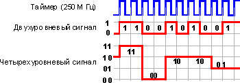 Unlike its predecessors, Gigabit Ethernet always uses all 4 pairs for transmission at the same time. And at once in two directions. In addition, the information is not encoded by two levels as usual (0 and 1), but four (00.01,10.11). Those. The voltage level at any given time encodes not one, but two bits at once. This is done in order to reduce the modulation frequency from 250 MHz to 125 MHz. In addition, a fifth level has been added to create redundancy code. It makes it possible to correct errors at the reception. This type of coding is called five-level pulse-amplitude coding (PAM-5). In addition, in order to use all pairs simultaneously for receiving and transmitting, the network adapter subtracts its own transmitted signal from the common signal in order to receive the signal transmitted by the other party. Thus, a full duplex mode is implemented on a single channel.
Further more
10 Gigabit Ethernet is already fully used by providers, but does not apply in the SOHO segment, since apparently there is enough Gigabit Ethernet. 10GBE uses single- and multimode fiber as a propagation medium, with or without wavelength compaction , copper cables with an InfiniBand connector, as well as a twisted pair in the 10GBASE-T or IEEE 802.3an-2006 standard.
40 Gigabit Ethernet (or 40GbE ) and 100 Gigabit Ethernet (or 100GbE ). The development of these standards was completed in July 2010. Currently, leading network equipment manufacturers such as Cisco, Juniper Networks and Huawei are already developing and launching the first routers supporting these technologies.
In conclusion, it is worth mentioning the promising technology Terabit Ethernet . Bob Metcalf, the creator, suggested that the technology would be developed by 2015, and also said:
To implement Ethernet 1 TBit / s, it is necessary to overcome many limitations, including 1550-nanometer lasers and modulation with a frequency of 15 GHz. For the future network, we need new modulation schemes, as well as new fiber, new lasers, in general, all new
UPD : Thanks to Nickel3000 habrauser that prompted, about the fact that the connector, which I've called RJ45 all my life, is actually 8P8C .
UPD2:: Thanks to the Wott user for explaining why pins 1,2,3 and 6 are used.
Source: https://habr.com/ru/post/158177/
All Articles