Finishing the MR3020, rebuilding its kernel and configuring the developer’s toolbox
Good afternoon, dear habrovchane. Since recently the Chinese router TP-Link TL-MR3020 (or its hardware counterpart for the Chinese market TL-WR703N) has gained popularity in DIY projects, I decided to write an article on its doping and configuration options for my projects, especially that I had fun at work with him for the past few months. In the article I will try to consider aspects that do not cover most beginner articles - namely, practical examples of rebuilding its firmware and configuring convenient developer tools for themselves.
So, first a brief overview of what has already been said many times. Here is our experimental:

Initially, this is a Chinese router equipped with a USB port and positioned as a mobile 3G Internet distributor (a 3G modem is supposed to be plugged into USB). For the presence of a USB-port and small dimensions, it was loved by developers, because, in fact, we have a miniature computer with full-fledged Linux (OpenWRT) on board, equipped with USB and even having several free GPIOs. Sold for the sum of about 850 rubles in Moscow.
As for his fellow TL-WR703N. Hardware it is almost completely identical to the MR3020, but designed exclusively for the Chinese market, so we have to find it much more difficult. Of the differences, it is smaller in size (the size of the entire router , along with the case, is equal to the size of the MR3020 printed circuit board ), it has less GPIO (on which the LEDs of the 3020 hang), and, according to unverified data, the antenna is slightly worse than a Wi-Fi antenna.
As for the various mods and hacks described in the network - mainly on foreign sites, they describe how to work with 703N, but 99.99% of these hacks are suitable for the MR3020 without any changes.
The hardware is represented by this:
Further, I strongly recommend that you read the wiki.openwrt.org/toh/tp-link/tl-mr3020 and wiki.openwrt.org/toh/tp-link/tl-wr703n articles and related materials to get the necessary ideas about these routers and OpenWRT, since I consider it inexpedient to simply reprint already written to the wiki in this article.
If there is a basic understanding of working with OpenWRT, go ahead.
So, what is most upset about this router?
So let's start in order.
As for point 0 - all we can do about it is to switch to another hardware platform. Available to the developer - board Carambola . Almost identical to the characteristics of the router, almost identical in size, almost identical in price (not counting the delivery). Designed for developers, a bunch of GPIO, you can solder what you want.
Of the shortcomings - schematics, contrary to popular belief, still closed. Only the schematics of their girlboard is opened, into which this carambola is inserted.
As well as the disadvantages include the cost of delivery and waiting time - the router is much cheaper and faster (you can immediately buy it for 850 rubles in a nearby store).
Plus, the ambiguous property of a carambola, which cannot be attributed either to the merits or to the disadvantages - neither USB connectors nor isolation with Ethernet connectors are mounted on the board - only bare pins. In case you design your baseboard, in which carambola will be stuck, this is a definite plus. If you need a quick decision from the series “bought ready and connected” - you have to wave a soldering iron.
Go to step 1.
')
In principle, it all depends on your needs. If you wish, you can fuck up in these unfortunate 4 meters, and then make sure that, don't let Von Neumann, not write down what a heavy log from the program.
I personally recommend the memory immediately expand and forget about the ROM forever. This is one of those things that will provide you with the comfort of working without constant thoughts of “how much I have left”, so let's talk about how to implement this plan.
Let's start with the most exotic - you can solder the flash drive itself.
What are the advantages of the solution? Obviously, the fact that everything remains integrated into the board of the router - nothing hangs outside, consumption remains low.
What are the cons? The fact that there is a seat under the body of the SO-8, in which of the backward-compatible flash drives there are only 8-meter. This is not the extension that I meant when I say “comfortable work”. However, if you are critical, plus this decision is quite feasible. Read about it here . In short, you will need to rebuild the bootloader and the core after soldering, not forgetting to patch it for the capacity of the flash memory, the placement of the system and the chip identifier in it, without which the device will refuse to start.
An even more exotic option is to place an incompatible USB stick on the external board, and, having soldered the router's native memory, have control pins (SPI bus) on it. This will allow you to go beyond 8 megabytes, but it will require another patch of the kernel and bootloader for Linux to recognize this flash drive. Option for a very big fan. Its variation is the use of one of the free GPIOs as a software pin for selecting a slave on the bus (SS) and connecting an additional flash drive in parallel to the existing one. If the previous one was for amateurs, then this one is for pervert necromancers who want to get a monster made of pieces of corpses. However, realizable, in my opinion.
Finally, the traditional solution is to use external memory with a USB interface.
Pros - fast, convenient, does not require rebuilding the kernel (only installing the appropriate modules) and absolutely does not require rebuilding the bootloader. You can expand the memory as much as you like by putting a flash drive on 8 GB. I forgot about the problems with the free space on the router.
Minuses - one USB-port is occupied, the current consumption increases milliamperes by 50. In case of mounting it as a root FS (it will be discussed later), the load time increases. The flash drive itself can be big - it's not always nice when such an appendage hangs out.
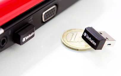
So let's start with the last minus (the size of a flash drive) and think about what can be done with it. After reviewing the market, I came in two options "out of the box" and one - amateur radio. As for the first two, everything is simple here: there are very tiny flash drives and very tiny micro-SD card readers on the market:
Verbatim Netbook USB Drive
Hama card reader / writer

In principle, both options are miniature enough not to irritate being stuck in USB, however, I initially intended to solder the controller chip and place it on my motherboard to get rid of the case and make the device more integrated - all extensions and additional power I planned to place on the second board, the size of the router itself. I stopped at the card reader, since this option seemed to me more flexible in terms of the possibility of choosing a carrier in terms of volume and speed of reading, as well as its replacement. After acquiring a card reader, I removed a part of the case from it (everything else was rigidly embedded in the USB connector itself, a micro-SD card was also inserted there), which can be seen in the photo below.
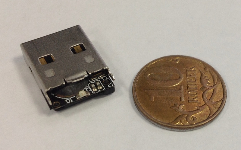
To my great disappointment, the USB-2-SD bridge was designed as an unpackaged chip flooded with a compound not intended for soldering. However, having intercepted the VID and PID of this device, I was able to find the appropriate chip. This turned out to be the creation of the Chinese firm Silicon Motion. Yes, they made these microcircuits in the package version. Perhaps they could even be obtained from us. The problem was that this bridge was the traditional for such solutions 8051-core + SD controller + USB controller in one chip, and to make it work, software was needed, which such companies do not provide to single buyers.
Based on this, we can conclude (the above-mentioned amateur radio solution): if you want to solve this problem nicely, and place on your motherboard not someone else's (albeit a very miniature card reader), and you can buy any of the controllers with the SD USB interface on board (for example, some kind of ST32F103), spend time implementing USB-mass storage there (discussed in the examples to the STM USB library) and use it as a single-chip USB-2-SD bridge for your router or any other similar project.
I didn’t do this for lack of time (although I’ll be able to get together sometime), plus I was somewhat doubtful that I would be able to occupy a smaller area on the board or comparable to this foreign card reader - without a case it became so small that it looked just like one from small developer modules or some shielded components (the screen view created remnants of the USB connector, which serve as a stop for the micro-SD). As for the USB ports. Of course, any Chinese USB hub comes to the rescue. However, as practice has shown, they are mostly made on the same chip (AU6256) regardless of the brand, and have a very, very unpleasant feature - to consume 100 mA x 5V (half a watt!) Without being involved at all. This, to be honest, strained me somewhat - you stick an empty hub into the USB port and it starts to consume more than the router itself.
There are similar chips from all your favorite Texas Instruments - this one, for example (TUSB2046B), whose datasheet states 40 mA consumption - again, until we got to check it out, but I tend to believe TI more than the Chinese.
Go to step 3.
On this account, you can voice two news. The good thing is that RAM can be painlessly replaced with a compatible microchip of 64 megabytes, of which, most likely, for the vast majority of experiments is more than enough. You do not need a rewrite, you do not need to patch the loaders and kernels. This is written in detail here.
The bad news is that all such solutions include the above mentioned routers, their big brothers from ASUS (such as the WL-500), and the developer Carambola are built on the oldest DDR1 chips, and finding a compatible 64-megabyte is now a big problem. Possible sources are listed at the link above - they are old memory modules (mainly from different laptops) - but when you google, most often there are not offers for sale, but prayers for flea markets from the same electronics engineers, who list this list word for word and asked to respond to the owners of at least one such strap, surprisingly to the surrounding people.
This, by the way, is one of the reasons why I would very much like to see a similar solution on some modern chips, say SITARA, from Texas Instruments - these are modern, easily accessible processors with the ARM core, which Linux has long been ported to. They are accompanied by apnotes with typical dev-boards schemes, SDK, and other buns, besides they work with DDR3. However, the development of such a fee requires a large amount of time and quite a solid investment (LUT will not help, we need multilayered ones), so I don’t dare to do this yet, especially since there is no need for a specific task. Perhaps someone is already engaged in this / is planning to do it - one could cooperate - the goal is to make a minimal single-board computer similar to Carambole - without screwing up excess iron, as a launching platform for developers to replace such router solutions.
But back to our routers. Having finished the review of iron, we proceed directly to configuring and reassembling.
Immediately voiced tasks. What did I want to accomplish by reassembling the core?
The rebuilding process itself is perfectly described here , I recommend reading until enlightenment, because, again, we will not rewrite a hundred times "enter the command make menuconfig to configure your kernel."
I suppose that at the time of reading this paragraph, you have already completed all the points described in the article before, in fact, menuconfig, and even tried to assemble the kernel, making sure that everything works. In principle, it worked out for me the first time, which means you shouldn’t cause problems - all the steps are quite transparent. The only thing I’ll note is that in case of any problems, oddly enough, it helps to make make dirclean , which cleans not only what you have found, but also what the system itself has created - that is, collected tools and so on.
If this does not help either, then it is worth trying to make make distclean - it cleans everything up altogether, including what the system has done. After that, the whole build will go from the very beginning, very, very long, but there is a chance that problems will not arise anymore. Do not do it unnecessarily, if you do not want to wait a few hours until everything comes together.
Do not forget to go to the menuconfig, select the correct target and target profile (Atheros AR7xxx / AR9xxx, TP-Link TL-MR3020), then save, and say make defconfig, which will fill our config deflatnymi for MR3020 values.
After running make menuconfig, I took almost everything out of the build, including iptables and their ilk - firstly, because it’s not a router anymore, and secondly, because all this can be easily delivered later. Therefore, we go through the menus and demolish everything that we do not need.
I left the following:
Everything else was disabled, or compiled as modules for subsequent installation.
At this stage, it will not hurt to crash your kernel, then flash it, following the instructions from the OpenWRT wiki:
If after that the router boots successfully - pay attention to MOTD (message of the day, invitation after login) - the build number should change there - congratulations, you have successfully assembled your kernel and changed the system. If the router refuses to boot - it doesn't matter, the situation can be saved with the help of a smart bootloader, which you, fortunately, did not touch - again, follow the instructions from the wiki (you will need usb - rs232 adapter).
We now turn to configs. It is logical to assume that the FS is embedded in the image flashing into the flash, and lies somewhere among the sources of OpenWRT. This is so, you can find your FS along the way
openwrt / trunk / build_dir / target-mips_r2_uClibc-0.9.33.2 / root-ar71xx
(in the future I will write all the paths as presented on my computer, openwrt is the directory in which the source codes were made)
Here you can edit anything and not be afraid to spoil your build system greatly, because this directory is generated anew for each build. Therefore, we first configure the kernel, assemble it, and then make changes here, and add the necessary modules separately, without rebuild the kernel. If something is messed up, then just re-do make , and the directory will be restored. To build its image from openwrt / trunk, we issue the command make target / install
There is, however, a more fundamental way - to edit the contents of the / openwrt / trunk / package / base-files / files directory - there are so-called “skeletons” to generate the target FS, which are not overwritten by the kernel rebuild. But, unlike the method described above, there is no way to find a complete image of the file system in the form in which it will be on the target machine and it is easy to spoil something irreversibly, so I didn’t go there much.
In general, at this stage you can begin to customize the image. And the first thing we will do is edit the / etc / config / fstab config so that at startup the system perceives the flash drive as the root.
A little help: this is done through overlayfs, the essence of which is that in the transparent mode for the user, he is shoved with the contents of several file systems. What is it for? Well, for example, it is initially involved in OpenWRT, even if you do not want to use a USB flash drive - the SquashFS file system there, which takes up little space, but read-only. In order for the user to be able to edit files (and at the same time everything that was not edited remained in the convenient SquashFS) this overlay is used. Two FSs are merged into one, and, in general, data are taken from SquashFS, but as soon as the user edits a file, a copy is created in the section readable and writeable (by default, there is JFFS). When the system implementing these overlays sees an available file with the same name in the JFFS overlay, it already slips the user onto it, while leaving all other files still from SquashFS.
Thus, no matter what we change in the router, it is necessary to disable the overlays and we will get our read-only FS in its original form, which is used for the recovery mode of the router (which I somehow never got, although I tried once) .
By the way, for the same reason, attempts to demolish any of the packages present in the firmware will lead to a decrease in free space - since the packages will remain where they were, plus an overlay copy of the settings files and other things affected by deletion will be created.
We use the same trick, but for the file system from a flash drive - the flash will be a complete copy of our file system, which we will prepare in advance as soon as we finish all the settings. When loading, it will be placed overlay on top of the built-in file system, and all changes will occur exclusively on a flash drive. Moreover, if you remove the flash drive before loading, the router will quietly boot (with its clean FS, the one that we are currently editing in the image), not forgetting to report that it was not possible to mount the specified overlay.
And so, we format the flash drive in ext4, create two partitions there - I created one for the swap (the first), the second for the root filesystem. If you wish, you can make a separate partition for / home or something else, but this was enough for me. Now, in the above / etc / config / fstab (the full path to which openwrt / trunk / build_dir / target-mips_r2_uClibc-0.9.33.2 / root-ar71xx / etc / config / fstab ) we write the following:
By this we inform that we need to mount an overlay root system in / dev / sda2 (the is_rootfs option is responsible for this, which says that it is not just a mount, but extroot) and a swap in / dev / sda1
Everything, the main thing is done. Further we configure everything at our discretion. Personally, I cleaned the configs, since they are generated immediately for all the boards, so in any of them we will see such magnificence as huge ifs of the form
You can mercilessly remove all cases from Iphas that are not related to our board, that is, to the MR3020. In addition, some configuration files, such as hotplag rules for ieee1394 or JTAG, which we do not physically have, do not make sense at all for this board and were generated exactly the same way, for compatibility of all this with other platforms - they can also be killed.
In addition, remember that some files in the / etc / config directory will be generated by the UCI system automatically. All this is implemented by scripts in / lib - you will notice them immediately. These include, for example, ar71xx.sh and functions.sh, which perform the initial configuration and pull the rest of the scripts (in particular, they just detect our board and populate that variable, ar71xx_board_name). So, for example, the /lib/wifi/mac80211.sh file at the very end contains the very lines that will be added to the / etc / config file for your radio:
Here you can correct the interface name, default point name, encryption, etc., then at the first start the contents of / etc / config / wireless will be generated in accordance with our edits.
After all the settings are completed, we need to make a complete copy of this file system on our flash drive, from which we will boot. At the same time, I strongly recommend making this trick: in / etc / banner is located the MOTD, which is displayed when logging in via SSH / Telnet to the system. You can change it as you like (I removed this annoying cocktail recipe, leaving only the OpenWRT logo), but one thing must be done with it: after copying the file system to the USB flash drive, we add something to this file so that it is different from the file in openwrt / trunk / build_dir / target-mips_r2_uClibc-0.9.33.2 / root-ar71xx / etc / config
For example, in the line we change the string ATTITUDE ADJUSTMENT (Bleeding Edge, r33444) to ATTITUDE ADJUSTMENT (Bleeding Edge, r33444, USB Overlay)
Now, thanks to this small trick, we can immediately understand after the login whether the overlay worked or not (for example, if a flash drive or the entire hub suddenly fell off)
After that, we’ll go back to the root of our sources (openwrt / trunk) and say make target / install - this will start the process of generating the final image, which will appear in the / openwrt / trunk / bin / ar71xx folder and be named openwrt-ar71xx-generic -tl-mr3020-v1-squashfs-sysupgrade.bin
After flashing it with the already known method, and after downloading (do not forget to insert the USB flash drive into the router!) And login via telnet we see the long-awaited greeting
ATTITUDE ADJUSTMENT (Bleeding Edge, r33444, USB Overlay)
Additionally, you can make sure by entering the df command. Do not forget to set the password with the passwd command, after which we are able to work via SSH instead of telnet. By the way, I do not recommend using an empty password not only for security reasons, but also because some utilities (which will be discussed below), even with the “remember password” option selected, consider that an empty password is not worth remembering and continues to annoyingly request it.
In the final part of the article we will talk about the reason for which all this, in fact, was started - on the development of a miracle device. Consider the tools for Windows, because From under ubunt I only compile kernels and modules. Of course, we still have the opportunity to write in C / C ++, cross-compiling our code as we cross-core, but this is a chore and not the best option - development speed and maintainability of the code are much higher in languages like Java, C # and different scripting types Python and Ruby . There is a Yawamashin under OpenWRT, but, according to the igor_suhorukov tests , it barely creeps. True, igor_suhorukov assembled a more lightweight phoneME machine for OpenWRT, but I never got around to testing it. Therefore, we will proceed from what is available to us, and a whole pile of scripting languages is available to us - Python, Ruby, Lua, Perl
I, frankly, are not at all fond of dynamically typed languages and scripts in general, but from the above set I decided to choose a python - once you turn to dark forces for help, then let it be the world's most famous and gripping dark forces.
We go to the router via SSH and install the packages we need:
This will install an SFTP server and, in fact, a python interpreter.
Next, we install a free utility on our WinSCP development machine that will allow us to easily climb the router's file system and share files with it. Let's create a new configuration in WinSCP: in the Host Name field, set the IP address or network name of our router, leave the port by default, enter the user name and password, select the protocol and choose SFTP.

Click "Login" and get full access to the FS of the router - this will speed up the process of editing configs, etc., if such a need arises.
Now download and install a great IDE from a well-known company JetBrains - PyCharm . We make sure that the version was not lower than 2.6 - in the past there is a bug, because of which remote debugging did not work.
Go to File - Settings - Deployment , click on the plus sign above the list to add a new server deployment. In the window that appears, enter the name, for example, MR3020 and select the SFTP protocol.
Next, we configure the deployment server: on the Connection tab, we specify the address of our router in the SFTP Host field, leaving the Port and Root Path fields by default.
Enter the username and password in the appropriate fields, put a tick "Save Password", so that we are not asked for each deploy. After that, you can click "Test SFTP connection" to make sure everything went fine.

Go through WinSCP or SSH to our router and create somewhere where it is convenient, for example, in / root, the directory pyHelpers - here you will copy the supporting IDE scripts.
Go to File - Settings - Project Interpreter - Python Interpreters and click on the plus sign on the right, choosing “Remote ...” in the drop-down menu after this. In the window that appears, click on the link "Fill from deployment settings", and select the previously configured deployment server named MR3020. In the "Python interpreter path" and "Copy PyCharm helpers to" fields, specify the path to the python binary on the router (the default is / usr / bin / python ) and the path to the directory for helpers we created - / root / PyHelpers

After clicking “OK” we recline on the back of the chair and wait until the IDE communicates with the interpreter on the router and builds a list of its capabilities and libraries with the help of its helpers.
Next comes the most interesting thing: when we want to start developing for our router, we create a new project, choosing our configured Remote Python as interpreter. Next, go to File - Settings - Deployment on the Mappings tab and select the path to our project on the router, in the Deployment Path on server 'MR3020' field. Do not forget to click "Use this as default server".
In the Tools - Deployment - Options menu, we set the deployment mode that is convenient for us in the field “Upload changed files automatically to default server” - for me this is “On explicit save action” - now when you press CTRL + S, the changed files will automatically applaud the router.
Now you can add the first file to the project and write the long-awaited print “Hello World” line there. Save the file, and see how the IDE in the console below reports on the successful upload of the file to the server. Next, right-click on the file name in the project tree and select "Run" - this will automatically create a configuration for launch. If something is wrong and the program does not start, go to the Run - Edit Configurations and check that the path to the script on the router is registered in the Script field. The result of the program will be displayed in the console at the bottom of the screen.
That's all. Now we have a powerful modern IDE that allows you to write on Python on your development machine, automatically uploading scripts to the target platform (router), executing them there, and outputting the result to the IDE console. As well as allowing them to debug and trace. Due to the exclusion of steps from the process, “wrote, compiled, transferred to the router, entered the router, launched, looked, did not work, returned to the developer machine” development speed grows many times, and portability of Python scripts ensures that most of your tasks in one form or another, it was solved by someone and framed in the form of libraries - it’s enough just to google.
For example, when developing a project at work, GPS was easily bolted to the router at the expense of the PyNMEA library.
The MR3020 will be an excellent “brain” for your robots or home automation systems, especially if you combine its capabilities with real-time processing on the same STM32 - in this case, the small M3 cortex will serve as hardware controllers of low-level systems, sending USB information and receiving commands from the router, the more ponderous part of the algorithms of which will be written on a convenient python. For example, in the case of robots, the STM32 controller excellently serves as a servo controller, generating a PWM signal, and also collects information from various sensors, collects it into a packet and sends it to the router, while Python scripts implement higher-level "behavior".
Successful developments!
Introduction
So, first a brief overview of what has already been said many times. Here is our experimental:
Initially, this is a Chinese router equipped with a USB port and positioned as a mobile 3G Internet distributor (a 3G modem is supposed to be plugged into USB). For the presence of a USB-port and small dimensions, it was loved by developers, because, in fact, we have a miniature computer with full-fledged Linux (OpenWRT) on board, equipped with USB and even having several free GPIOs. Sold for the sum of about 850 rubles in Moscow.
As for his fellow TL-WR703N. Hardware it is almost completely identical to the MR3020, but designed exclusively for the Chinese market, so we have to find it much more difficult. Of the differences, it is smaller in size (the size of the entire router , along with the case, is equal to the size of the MR3020 printed circuit board ), it has less GPIO (on which the LEDs of the 3020 hang), and, according to unverified data, the antenna is slightly worse than a Wi-Fi antenna.
As for the various mods and hacks described in the network - mainly on foreign sites, they describe how to work with 703N, but 99.99% of these hacks are suitable for the MR3020 without any changes.
The hardware is represented by this:
- Atheros AR7240 CPU (400Mhz)
- Atheros AR9331 Chipset (integrated wireless)
- 802.11 b / g / n 150Mbps (130Mbps real)
- wireless power output 20dBm - 100mW
- 4 MB flash memory
- 32 MB RAM
- USB 2.0 port
Further, I strongly recommend that you read the wiki.openwrt.org/toh/tp-link/tl-mr3020 and wiki.openwrt.org/toh/tp-link/tl-wr703n articles and related materials to get the necessary ideas about these routers and OpenWRT, since I consider it inexpedient to simply reprint already written to the wiki in this article.
If there is a basic understanding of working with OpenWRT, go ahead.
Ways of development
So, what is most upset about this router?
- 0. The zero point unites in itself what, alas, we cannot influence in any way. This is, in fact, the router origin of iron - that is, the fact that it is not intended for developers, the schematics is closed, and, generally speaking, we have no right to modify it and use it in commercial products. And also the fact that when the Chinese get tired of producing it, all decisions on it will have to be urgently dragged under something else.
- 1. A small amount of ROM - at our disposal only 4 megabytes of flash memory, about 1.5 of which are occupied by firmware
- 2. One USB port - given that a lot of peripherals are often required (cameras, modems, GPS, flash drives) - this is also sad.
- 3. Not a very large amount of RAM - 32 megabytes.
So let's start in order.
Iron was not soldered to us
As for point 0 - all we can do about it is to switch to another hardware platform. Available to the developer - board Carambola . Almost identical to the characteristics of the router, almost identical in size, almost identical in price (not counting the delivery). Designed for developers, a bunch of GPIO, you can solder what you want.
Of the shortcomings - schematics, contrary to popular belief, still closed. Only the schematics of their girlboard is opened, into which this carambola is inserted.
As well as the disadvantages include the cost of delivery and waiting time - the router is much cheaper and faster (you can immediately buy it for 850 rubles in a nearby store).
Plus, the ambiguous property of a carambola, which cannot be attributed either to the merits or to the disadvantages - neither USB connectors nor isolation with Ethernet connectors are mounted on the board - only bare pins. In case you design your baseboard, in which carambola will be stuck, this is a definite plus. If you need a quick decision from the series “bought ready and connected” - you have to wave a soldering iron.
Go to step 1.
')
Small ROM
In principle, it all depends on your needs. If you wish, you can fuck up in these unfortunate 4 meters, and then make sure that, don't let Von Neumann, not write down what a heavy log from the program.
I personally recommend the memory immediately expand and forget about the ROM forever. This is one of those things that will provide you with the comfort of working without constant thoughts of “how much I have left”, so let's talk about how to implement this plan.
Let's start with the most exotic - you can solder the flash drive itself.
What are the advantages of the solution? Obviously, the fact that everything remains integrated into the board of the router - nothing hangs outside, consumption remains low.
What are the cons? The fact that there is a seat under the body of the SO-8, in which of the backward-compatible flash drives there are only 8-meter. This is not the extension that I meant when I say “comfortable work”. However, if you are critical, plus this decision is quite feasible. Read about it here . In short, you will need to rebuild the bootloader and the core after soldering, not forgetting to patch it for the capacity of the flash memory, the placement of the system and the chip identifier in it, without which the device will refuse to start.
An even more exotic option is to place an incompatible USB stick on the external board, and, having soldered the router's native memory, have control pins (SPI bus) on it. This will allow you to go beyond 8 megabytes, but it will require another patch of the kernel and bootloader for Linux to recognize this flash drive. Option for a very big fan. Its variation is the use of one of the free GPIOs as a software pin for selecting a slave on the bus (SS) and connecting an additional flash drive in parallel to the existing one. If the previous one was for amateurs, then this one is for pervert necromancers who want to get a monster made of pieces of corpses. However, realizable, in my opinion.
Finally, the traditional solution is to use external memory with a USB interface.
Pros - fast, convenient, does not require rebuilding the kernel (only installing the appropriate modules) and absolutely does not require rebuilding the bootloader. You can expand the memory as much as you like by putting a flash drive on 8 GB. I forgot about the problems with the free space on the router.
Minuses - one USB-port is occupied, the current consumption increases milliamperes by 50. In case of mounting it as a root FS (it will be discussed later), the load time increases. The flash drive itself can be big - it's not always nice when such an appendage hangs out.
So let's start with the last minus (the size of a flash drive) and think about what can be done with it. After reviewing the market, I came in two options "out of the box" and one - amateur radio. As for the first two, everything is simple here: there are very tiny flash drives and very tiny micro-SD card readers on the market:
Verbatim Netbook USB Drive
Hama card reader / writer
In principle, both options are miniature enough not to irritate being stuck in USB, however, I initially intended to solder the controller chip and place it on my motherboard to get rid of the case and make the device more integrated - all extensions and additional power I planned to place on the second board, the size of the router itself. I stopped at the card reader, since this option seemed to me more flexible in terms of the possibility of choosing a carrier in terms of volume and speed of reading, as well as its replacement. After acquiring a card reader, I removed a part of the case from it (everything else was rigidly embedded in the USB connector itself, a micro-SD card was also inserted there), which can be seen in the photo below.
To my great disappointment, the USB-2-SD bridge was designed as an unpackaged chip flooded with a compound not intended for soldering. However, having intercepted the VID and PID of this device, I was able to find the appropriate chip. This turned out to be the creation of the Chinese firm Silicon Motion. Yes, they made these microcircuits in the package version. Perhaps they could even be obtained from us. The problem was that this bridge was the traditional for such solutions 8051-core + SD controller + USB controller in one chip, and to make it work, software was needed, which such companies do not provide to single buyers.
Based on this, we can conclude (the above-mentioned amateur radio solution): if you want to solve this problem nicely, and place on your motherboard not someone else's (albeit a very miniature card reader), and you can buy any of the controllers with the SD USB interface on board (for example, some kind of ST32F103), spend time implementing USB-mass storage there (discussed in the examples to the STM USB library) and use it as a single-chip USB-2-SD bridge for your router or any other similar project.
I didn’t do this for lack of time (although I’ll be able to get together sometime), plus I was somewhat doubtful that I would be able to occupy a smaller area on the board or comparable to this foreign card reader - without a case it became so small that it looked just like one from small developer modules or some shielded components (the screen view created remnants of the USB connector, which serve as a stop for the micro-SD). As for the USB ports. Of course, any Chinese USB hub comes to the rescue. However, as practice has shown, they are mostly made on the same chip (AU6256) regardless of the brand, and have a very, very unpleasant feature - to consume 100 mA x 5V (half a watt!) Without being involved at all. This, to be honest, strained me somewhat - you stick an empty hub into the USB port and it starts to consume more than the router itself.
There are similar chips from all your favorite Texas Instruments - this one, for example (TUSB2046B), whose datasheet states 40 mA consumption - again, until we got to check it out, but I tend to believe TI more than the Chinese.
Go to step 3.
Low RAM
On this account, you can voice two news. The good thing is that RAM can be painlessly replaced with a compatible microchip of 64 megabytes, of which, most likely, for the vast majority of experiments is more than enough. You do not need a rewrite, you do not need to patch the loaders and kernels. This is written in detail here.
The bad news is that all such solutions include the above mentioned routers, their big brothers from ASUS (such as the WL-500), and the developer Carambola are built on the oldest DDR1 chips, and finding a compatible 64-megabyte is now a big problem. Possible sources are listed at the link above - they are old memory modules (mainly from different laptops) - but when you google, most often there are not offers for sale, but prayers for flea markets from the same electronics engineers, who list this list word for word and asked to respond to the owners of at least one such strap, surprisingly to the surrounding people.
This, by the way, is one of the reasons why I would very much like to see a similar solution on some modern chips, say SITARA, from Texas Instruments - these are modern, easily accessible processors with the ARM core, which Linux has long been ported to. They are accompanied by apnotes with typical dev-boards schemes, SDK, and other buns, besides they work with DDR3. However, the development of such a fee requires a large amount of time and quite a solid investment (LUT will not help, we need multilayered ones), so I don’t dare to do this yet, especially since there is no need for a specific task. Perhaps someone is already engaged in this / is planning to do it - one could cooperate - the goal is to make a minimal single-board computer similar to Carambole - without screwing up excess iron, as a launching platform for developers to replace such router solutions.
But back to our routers. Having finished the review of iron, we proceed directly to configuring and reassembling.
Reassemble the kernel
Immediately voiced tasks. What did I want to accomplish by reassembling the core?
- Since OpenWRT easily allows you to load everything you need from the repository, including kernel modules, I found it unnecessary to build into my build what is not required to start the system.
- In order to avoid unnecessary problems with the paths and other misunderstandings, I decided to transfer the entire root file system to a USB flash drive, and not just mount it as an additional disk. This solves all possible problems of “not finding” any libraries by packages due to installing them in the wrong location and makes using the router more convenient, in my opinion. This implies the requirements for core modules - support for usb, ext4 file system, external disk
- Minor router presets are annoying when after flashing you have to start all over again, so some configs can be fixed already at the file system level in the firmware so as not to do this every time - for example, it’s much more convenient for me that the default MR3020 would be DHCP after the flashing client, getting IP and becoming part of my network, and not trying to pretend to be a server, kicking my real router - simplifies the development / debugging process, no need to poke around every time, choosing between "there is an Internet" and "there is a connection with MR3020 »
The rebuilding process itself is perfectly described here , I recommend reading until enlightenment, because, again, we will not rewrite a hundred times "enter the command make menuconfig to configure your kernel."
I suppose that at the time of reading this paragraph, you have already completed all the points described in the article before, in fact, menuconfig, and even tried to assemble the kernel, making sure that everything works. In principle, it worked out for me the first time, which means you shouldn’t cause problems - all the steps are quite transparent. The only thing I’ll note is that in case of any problems, oddly enough, it helps to make make dirclean , which cleans not only what you have found, but also what the system itself has created - that is, collected tools and so on.
If this does not help either, then it is worth trying to make make distclean - it cleans everything up altogether, including what the system has done. After that, the whole build will go from the very beginning, very, very long, but there is a chance that problems will not arise anymore. Do not do it unnecessarily, if you do not want to wait a few hours until everything comes together.
Do not forget to go to the menuconfig, select the correct target and target profile (Atheros AR7xxx / AR9xxx, TP-Link TL-MR3020), then save, and say make defconfig, which will fill our config deflatnymi for MR3020 values.
After running make menuconfig, I took almost everything out of the build, including iptables and their ilk - firstly, because it’s not a router anymore, and secondly, because all this can be easily delivered later. Therefore, we go through the menus and demolish everything that we do not need.
I left the following:
- In the Base System, we are looking for the block-mount to be sure that it is necessary to connect the disks, from the fact that the default remains base-files, busybox, dnsmasq, dropbear, hotplug2 (don't forget it, if you don’t want to stay without usb connection notifications and button presses), mtd, opkg, uci
- In Kernel Modules, go to the Filesystems section and activate kmod-fs-ext4 there .
If you want, you can choose some other system, but ext4 alone is enough. I have not installed all the other kernel modules, except for several points present from the default LED-modules (if you remove them, of course, the router will not blink its LEDs and you won’t even know how the boot process went) named kmod-gpio-button-hotplug , giving notifications when the router buttons are pressed (it has one button and one three-position lever, also considered two buttons Linux ), the default kmod-wdt-ath79 is there, very important to us kmod-usb -ochi, kmod-usb-storage-extras, kmod-usb-uchi, kmod-usb2 from USB Support and Embedded Driver Enjoy Wi-Fi - kmod-ath9k from Wireless Drivers.
Everything else was disabled, or compiled as modules for subsequent installation.
At this stage, it will not hurt to crash your kernel, then flash it, following the instructions from the OpenWRT wiki:
cd /tmp wget ------.bin mtd write -.bin reboot If after that the router boots successfully - pay attention to MOTD (message of the day, invitation after login) - the build number should change there - congratulations, you have successfully assembled your kernel and changed the system. If the router refuses to boot - it doesn't matter, the situation can be saved with the help of a smart bootloader, which you, fortunately, did not touch - again, follow the instructions from the wiki (you will need usb - rs232 adapter).
We now turn to configs. It is logical to assume that the FS is embedded in the image flashing into the flash, and lies somewhere among the sources of OpenWRT. This is so, you can find your FS along the way
openwrt / trunk / build_dir / target-mips_r2_uClibc-0.9.33.2 / root-ar71xx
(in the future I will write all the paths as presented on my computer, openwrt is the directory in which the source codes were made)
Here you can edit anything and not be afraid to spoil your build system greatly, because this directory is generated anew for each build. Therefore, we first configure the kernel, assemble it, and then make changes here, and add the necessary modules separately, without rebuild the kernel. If something is messed up, then just re-do make , and the directory will be restored. To build its image from openwrt / trunk, we issue the command make target / install
There is, however, a more fundamental way - to edit the contents of the / openwrt / trunk / package / base-files / files directory - there are so-called “skeletons” to generate the target FS, which are not overwritten by the kernel rebuild. But, unlike the method described above, there is no way to find a complete image of the file system in the form in which it will be on the target machine and it is easy to spoil something irreversibly, so I didn’t go there much.
In general, at this stage you can begin to customize the image. And the first thing we will do is edit the / etc / config / fstab config so that at startup the system perceives the flash drive as the root.
A little help: this is done through overlayfs, the essence of which is that in the transparent mode for the user, he is shoved with the contents of several file systems. What is it for? Well, for example, it is initially involved in OpenWRT, even if you do not want to use a USB flash drive - the SquashFS file system there, which takes up little space, but read-only. In order for the user to be able to edit files (and at the same time everything that was not edited remained in the convenient SquashFS) this overlay is used. Two FSs are merged into one, and, in general, data are taken from SquashFS, but as soon as the user edits a file, a copy is created in the section readable and writeable (by default, there is JFFS). When the system implementing these overlays sees an available file with the same name in the JFFS overlay, it already slips the user onto it, while leaving all other files still from SquashFS.
Thus, no matter what we change in the router, it is necessary to disable the overlays and we will get our read-only FS in its original form, which is used for the recovery mode of the router (which I somehow never got, although I tried once) .
By the way, for the same reason, attempts to demolish any of the packages present in the firmware will lead to a decrease in free space - since the packages will remain where they were, plus an overlay copy of the settings files and other things affected by deletion will be created.
We use the same trick, but for the file system from a flash drive - the flash will be a complete copy of our file system, which we will prepare in advance as soon as we finish all the settings. When loading, it will be placed overlay on top of the built-in file system, and all changes will occur exclusively on a flash drive. Moreover, if you remove the flash drive before loading, the router will quietly boot (with its clean FS, the one that we are currently editing in the image), not forgetting to report that it was not possible to mount the specified overlay.
And so, we format the flash drive in ext4, create two partitions there - I created one for the swap (the first), the second for the root filesystem. If you wish, you can make a separate partition for / home or something else, but this was enough for me. Now, in the above / etc / config / fstab (the full path to which openwrt / trunk / build_dir / target-mips_r2_uClibc-0.9.33.2 / root-ar71xx / etc / config / fstab ) we write the following:
config mount option target / option device /dev/sda2 option fstype ext4 option options rw,sync option enabled 1 option is_rootfs 1 config swap option device /dev/sda1 option enabled 1 By this we inform that we need to mount an overlay root system in / dev / sda2 (the is_rootfs option is responsible for this, which says that it is not just a mount, but extroot) and a swap in / dev / sda1
Everything, the main thing is done. Further we configure everything at our discretion. Personally, I cleaned the configs, since they are generated immediately for all the boards, so in any of them we will see such magnificence as huge ifs of the form
case $(ar71xx_board_name) in wzr-hp-ag300h) ar922x_disable_gpio_jtag $phyname ;; You can mercilessly remove all cases from Iphas that are not related to our board, that is, to the MR3020. In addition, some configuration files, such as hotplag rules for ieee1394 or JTAG, which we do not physically have, do not make sense at all for this board and were generated exactly the same way, for compatibility of all this with other platforms - they can also be killed.
In addition, remember that some files in the / etc / config directory will be generated by the UCI system automatically. All this is implemented by scripts in / lib - you will notice them immediately. These include, for example, ar71xx.sh and functions.sh, which perform the initial configuration and pull the rest of the scripts (in particular, they just detect our board and populate that variable, ar71xx_board_name). So, for example, the /lib/wifi/mac80211.sh file at the very end contains the very lines that will be added to the / etc / config file for your radio:
cat <<EOF config wifi-device radio$devidx option type mac80211 option channel ${channel} option macaddr $(cat /sys/class/ieee80211/${dev}/macaddress) option hwmode 11${mode_11n}${mode_band} $ht_capab # REMOVE THIS LINE TO ENABLE WIFI: option disabled 1 config wifi-iface option device radio$devidx option network lan option mode ap option ssid OpenWrt option encryption none EOF devidx=$(($devidx + 1)) done } Here you can correct the interface name, default point name, encryption, etc., then at the first start the contents of / etc / config / wireless will be generated in accordance with our edits.
After all the settings are completed, we need to make a complete copy of this file system on our flash drive, from which we will boot. At the same time, I strongly recommend making this trick: in / etc / banner is located the MOTD, which is displayed when logging in via SSH / Telnet to the system. You can change it as you like (I removed this annoying cocktail recipe, leaving only the OpenWRT logo), but one thing must be done with it: after copying the file system to the USB flash drive, we add something to this file so that it is different from the file in openwrt / trunk / build_dir / target-mips_r2_uClibc-0.9.33.2 / root-ar71xx / etc / config
For example, in the line we change the string ATTITUDE ADJUSTMENT (Bleeding Edge, r33444) to ATTITUDE ADJUSTMENT (Bleeding Edge, r33444, USB Overlay)
Now, thanks to this small trick, we can immediately understand after the login whether the overlay worked or not (for example, if a flash drive or the entire hub suddenly fell off)
After that, we’ll go back to the root of our sources (openwrt / trunk) and say make target / install - this will start the process of generating the final image, which will appear in the / openwrt / trunk / bin / ar71xx folder and be named openwrt-ar71xx-generic -tl-mr3020-v1-squashfs-sysupgrade.bin
After flashing it with the already known method, and after downloading (do not forget to insert the USB flash drive into the router!) And login via telnet we see the long-awaited greeting
ATTITUDE ADJUSTMENT (Bleeding Edge, r33444, USB Overlay)
Additionally, you can make sure by entering the df command. Do not forget to set the password with the passwd command, after which we are able to work via SSH instead of telnet. By the way, I do not recommend using an empty password not only for security reasons, but also because some utilities (which will be discussed below), even with the “remember password” option selected, consider that an empty password is not worth remembering and continues to annoyingly request it.
Developer Toolkit
In the final part of the article we will talk about the reason for which all this, in fact, was started - on the development of a miracle device. Consider the tools for Windows, because From under ubunt I only compile kernels and modules. Of course, we still have the opportunity to write in C / C ++, cross-compiling our code as we cross-core, but this is a chore and not the best option - development speed and maintainability of the code are much higher in languages like Java, C # and different scripting types Python and Ruby . There is a Yawamashin under OpenWRT, but, according to the igor_suhorukov tests , it barely creeps. True, igor_suhorukov assembled a more lightweight phoneME machine for OpenWRT, but I never got around to testing it. Therefore, we will proceed from what is available to us, and a whole pile of scripting languages is available to us - Python, Ruby, Lua, Perl
I, frankly, are not at all fond of dynamically typed languages and scripts in general, but from the above set I decided to choose a python - once you turn to dark forces for help, then let it be the world's most famous and gripping dark forces.
We go to the router via SSH and install the packages we need:
opkg update opkg install vsftpd python This will install an SFTP server and, in fact, a python interpreter.
Next, we install a free utility on our WinSCP development machine that will allow us to easily climb the router's file system and share files with it. Let's create a new configuration in WinSCP: in the Host Name field, set the IP address or network name of our router, leave the port by default, enter the user name and password, select the protocol and choose SFTP.
Click "Login" and get full access to the FS of the router - this will speed up the process of editing configs, etc., if such a need arises.
Now download and install a great IDE from a well-known company JetBrains - PyCharm . We make sure that the version was not lower than 2.6 - in the past there is a bug, because of which remote debugging did not work.
Go to File - Settings - Deployment , click on the plus sign above the list to add a new server deployment. In the window that appears, enter the name, for example, MR3020 and select the SFTP protocol.
Next, we configure the deployment server: on the Connection tab, we specify the address of our router in the SFTP Host field, leaving the Port and Root Path fields by default.
Enter the username and password in the appropriate fields, put a tick "Save Password", so that we are not asked for each deploy. After that, you can click "Test SFTP connection" to make sure everything went fine.
Go through WinSCP or SSH to our router and create somewhere where it is convenient, for example, in / root, the directory pyHelpers - here you will copy the supporting IDE scripts.
Go to File - Settings - Project Interpreter - Python Interpreters and click on the plus sign on the right, choosing “Remote ...” in the drop-down menu after this. In the window that appears, click on the link "Fill from deployment settings", and select the previously configured deployment server named MR3020. In the "Python interpreter path" and "Copy PyCharm helpers to" fields, specify the path to the python binary on the router (the default is / usr / bin / python ) and the path to the directory for helpers we created - / root / PyHelpers
After clicking “OK” we recline on the back of the chair and wait until the IDE communicates with the interpreter on the router and builds a list of its capabilities and libraries with the help of its helpers.
Next comes the most interesting thing: when we want to start developing for our router, we create a new project, choosing our configured Remote Python as interpreter. Next, go to File - Settings - Deployment on the Mappings tab and select the path to our project on the router, in the Deployment Path on server 'MR3020' field. Do not forget to click "Use this as default server".
In the Tools - Deployment - Options menu, we set the deployment mode that is convenient for us in the field “Upload changed files automatically to default server” - for me this is “On explicit save action” - now when you press CTRL + S, the changed files will automatically applaud the router.
Now you can add the first file to the project and write the long-awaited print “Hello World” line there. Save the file, and see how the IDE in the console below reports on the successful upload of the file to the server. Next, right-click on the file name in the project tree and select "Run" - this will automatically create a configuration for launch. If something is wrong and the program does not start, go to the Run - Edit Configurations and check that the path to the script on the router is registered in the Script field. The result of the program will be displayed in the console at the bottom of the screen.
Conclusion
That's all. Now we have a powerful modern IDE that allows you to write on Python on your development machine, automatically uploading scripts to the target platform (router), executing them there, and outputting the result to the IDE console. As well as allowing them to debug and trace. Due to the exclusion of steps from the process, “wrote, compiled, transferred to the router, entered the router, launched, looked, did not work, returned to the developer machine” development speed grows many times, and portability of Python scripts ensures that most of your tasks in one form or another, it was solved by someone and framed in the form of libraries - it’s enough just to google.
For example, when developing a project at work, GPS was easily bolted to the router at the expense of the PyNMEA library.
The MR3020 will be an excellent “brain” for your robots or home automation systems, especially if you combine its capabilities with real-time processing on the same STM32 - in this case, the small M3 cortex will serve as hardware controllers of low-level systems, sending USB information and receiving commands from the router, the more ponderous part of the algorithms of which will be written on a convenient python. For example, in the case of robots, the STM32 controller excellently serves as a servo controller, generating a PWM signal, and also collects information from various sensors, collects it into a packet and sends it to the router, while Python scripts implement higher-level "behavior".
Successful developments!
Source: https://habr.com/ru/post/158127/
All Articles