A new type of wind generator produces electricity without blades.
We are all accustomed to the standard type of wind turbines, and with the word wind generator, most immediately imagine rotating blades. In some countries, there are whole wind power plants, which consist of many dozens, if not hundreds, of “windmills”. This method of obtaining energy has advantages, there are drawbacks. The main drawback is usually called noise, as well as an abundance of moving parts. It turns out that there are other, no less effective, methods of generating electricity by “catching” the wind. For example, an effective wind generator has already been developed, which has no moving blades at all.
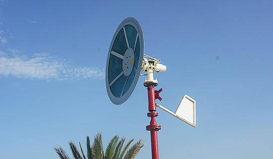
Such a wind generator, created by the efforts of engineers of Saphon Energy, works on the principle of a sailboat. It is designed so that the “sail”, which in the photo is more like a plate, catches the wind, transforming the energy of the moving air mass into electricity. Due to the pressure of the wind (even a small one), the sail oscillates, facilitating the movement of small pistons located at the top of the system.
')
The pistons, in turn, start up a special hydraulic system that converts kinetic energy into electricity. According to the developers, Saphonian, the so-called system, does not contain either transmissions or “gearboxes”. In addition, such a system is practically silent. At the same time, the efficiency of such a system is 2.3 times higher than that of a conventional wind generator. In addition, the cost of maintaining the system in work is 45% lower than in the case of the traditional scheme of work.
The company has already received a patent (thanks to ilya42 ) for its invention this year, and is now looking for a partner to launch an industrial scheme for the production of its wind generators. In general, the system is quite interesting. There are, of course, many questions, including the efficiency of the system in different climatic zones, as well as the power of a wind generator of different sizes.
Reference to the patent was indicated above. But
Machine translation of the patent (fr.) Into Russian
The invention, the description of this technique, is a system for converting wind energy (CESG) into mechanical energy, and then electricity.
This wind power conversion system (CESG), described below, is not subject to the theoretical Betz limit (59%). Thus, this invention provides much higher performance than wind turbines are currently used.
The system (WECS) has a wheel (F) with a number of blades located around (see drawing No. l). The wheel (F) rotates in association to rotate around the axis (L) is fixed, due to the kinetic wind energy in the blades, providing the wheel (F) mechanical energy of rotation.
Flush to the axis (L), the holder (E), sufficiently rigid, provides the plate (or rear) series with double-acting cylinders (D). The latter may consist of one or more double-acting cylinders (see Figure 1 M 1). To simplify the present system description (WECS) has a series of three double acting cylinders. The distribution and positioning of the series by double-acting cylinders (D) on the bracket (E), to be sure in a certain way to ensure better functioning (see detailed drawing No, no l).
Piston rods from a set of double-acting cylinders (D) are connected to the ball joint body (), and that in order to provide it with the maximum degree of freedom in space,
allows movement and more fluid to the wind (see detailed drawing No, no l) and (photo number 7). The said body (A) has the shape and properties of the surface are determined, respectively, to achieve the coefficient of aerodynamic drag above and the maximum resultant wind force captured. In addition, the body (A) should have light weight possible. In this case, and not only on a part of its surface, it can be, for example, covered with a veil (see figure No. 2).
In order for the wheel (F) to rotate freely and independently of the body (A), the active surface (the surface facing the wind) is kept constantly exposed to the wind (see front view in drawings No. 3, N 4, No. 5 and No. 6).
Mounts on piston rods with double-acting cylinders (D) on the body (A) must be installed on an axis that coincides with the direction of the vector of the resulting wind force attacks on the body (A) (for details, do not pay Number L).
The rigid arm © is recessed on one side of the wheel (F) and supported on the other side, pivotally connected to the profile (B) U-shaped With the circular movements of the satellite, it turns out, therefore, with the wheel (F), and sliding on the peripheral parts of the body (A) (see picture number 2). In order to minimize the friction of the sliding profile (B), the latter can be in contact with the peripheral part of the body (A) with the help of rollers and the like. In addition, the peripheral parts of the body (A) should be sufficiently smooth and fairly rigid.
When the wind acts on the body (A), the latter rotates under the effect of the moment the net force of the wind, and from the section of the summary (B) and the body (A) the ball grows without interference through the Bonds, the stems of the double-acting cylinders (D) that are present in the diametrically region opposite slats (B). Rods with double acting cylinders (D) present in the return zone (zone side of profile (B)) are usually drawn (see Figure IM 3).
The presence of a circular motion of the satellite, the profile (B) rotates while sliding on the peripheral parts of the body (A), thereby changing the fulcrum of the net force of the wind (connecting the rod of the profile (B)), which is attached to the body (A). The rods are double acting cylinders (D), therefore, will be drawn and pushed, having a forward motion cycle (see Figures No. 3, No. 4, No. 5 and No. 6). Thus, the wind energy captured by the wind of the body (A) is converted into mechanical energy of the translational motion of the piston in double-acting cylinders (D), thereby creating pressure on the latter.
The view from the front, left, top and perspective figures No. 3, No. 4, No. 5 and No. 6 shows the actions of the body (A) on the stems by double-acting cylinders (D) and the behavior of the system (WECS) against the wind at different positions (0 °, 90 °, 180 ° and 270 °) of the profile (B) peripheral parts of the body (A).
The gondolas (D) nestles to the axis (L). This platform (J) contains mainly a hydraulic motor (H) and an electric generator (G), which can be connected via a speed multiplier (see drawing No. L).
During the back and forth movement of the pistons a row of double acting cylinders (D), they grow hydraulic fluid in the hydraulic circuit path (in red) convertible or pull or push, and through a row of valves (see figure No. 7). The latter also allows hydraulic fluid to be sucked into double acting cylinders (D) through the return hydraulic circuit (blue) and in one direction, "regardless of movement, pulling or pushing."
A hydraulic flow diagram (red) is connected to the input of a hydraulic motor (H). The back (blue) is also associated with the output of the hydraulic motor (H) (see Figure 7). Thus, the flow of hydraulic fluid under pressure, turns into a rotational movement of the motor shaft (H), which is connected to the axis of the electric generator (G) through a speed multiplier, creating such pure electricity (see figure No. 7).
In order to take into account the direction of the wind kept the system (WECS), can be equipped with an automatic orientation system allows it to turn on the mat (I) and keep the body (A) and the wheel (F) constantly face the wind, and this mode, up or down flow. In addition, orientation can be achieved with the help of the helm (K), a well-defined dimensions, fixed with the aid of the medium, the nacelle (J) (see figure No. L). In order to simplify the work of the orientation system (WECS), and not be limited to the decision of the rudder (K) in this case to consider as a good example.
Thus, the wind energy captured by the body (A) is converted into mechanical energy of the translation rotation and, accordingly, through rods from multiple cylinders (D) and hydraulic engine (H). This mechanical energy is converted into electrical energy with an electric generator (G). A link in this chain of energy conversion to the conversion of mechanical energy into mechanical energy of rotation can be insured without restrictions, through several other mechanisms, such as a crank or other ...
As was announced at the beginning of the technical description, the system (WECS) is not subject to the theoretical Betz limit (16/27%) and provides the best wind power conversion output. Only under the condition of the component is the Betz limit, in that the wheel (F), which has only a small surface area compared to the total active surface system (WECS). In addition, this wheel (F) serves only to change the position of the profile (B) in the circular motion of the satellite and the energy it captures is not required. Consider the energy conversion chain described above, or ultimately restore energy.
Via saphonenergy + DVICE
Source: https://habr.com/ru/post/157733/
All Articles