Development of automatic fire extinguishing system for server
I would like to start my article in the first place with an apology for the fact that it does not quite fit into IT topics, but I will try to be as close as possible to the IT world.
After reading this article, a person who, by the will of fate, will have to face the design of the simplest fire safety systems, will have a general concept of how this project should be ironed. How to arrange, what to draw, what programs to produce hydraulic calculation of the installation. A draft document is attached to this project, which you can freely take for yourself and use when developing your projects.
To begin with, I would like to note that in my opinion, at present there is a situation in which, it is quite possible that a student who graduated from an educational institution, has a very remote idea of what and how to do in his specialty. I was one of these students not so long ago, so I want to briefly share my work, I hope. That they will save you the nerves and time spent searching for samples and examples.
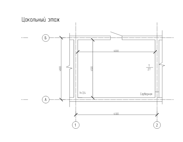
So let's set the source data, we have a server room with a total area of 27 m2. In our case, the geometric parameters of the room will be as follows
4.5x6x3.4m (LxWxH), our server will be located on the basement floor.
Since the area of our server room is more than 24 square meters, we need to equip it with an Automatic Fire Extinguishing System.
When developing an automatic fire extinguishing system, it will be very useful to familiarize yourself with “SP 5.13130.2009 Fire protection systems INSTALLATIONS FOR FIRE ALARM AND FIRE EXTINGUISHING AUTOMATIC” you can take it from the site of the Ministry of Emergency Situations
From the code of practice, we learn that there are several types of fire extinguishing systems (depending on the extinguishing agent):
')
Fire fighting water system
Water fire extinguishing system - sprayed water
Aerosol fire extinguishing system
Powder extinguishing system
Gas fire extinguishing system.
The first three systems do not suit us, because water (as well as its derivatives) and server water are not very compatible with each other. The powder extinguishing system will not work for us, because it is not able to extinguish the fire center in an inaccessible place (imagine that you have a server in the cabinet smoking and at this moment the system opens the powder extinguishing module over the cabinet, the powder falls on the top cover of the cabinet, the system reports fire, and in the meantime the source of fire continues to grow).
In essence, only 1 method remains, gas fire extinguishing by volume
(This means that the gas extinguishing agent will spread throughout the entire volume of the room).
At the moment there are several gas fire extinguishing compositions on the market.
This and CO2, this Inergen and Freon.
In practice, usually for small server rooms, freons are used.
(CO2 is dangerous for people and more difficult to store, Inergen (and similar compounds) are safer for humans (less risk of suffocation than CO2), have not so many side effects, but are poorly distributed in the market at the moment, although it is possible sometimes they will take away their chunk of the market from freons.
Freons are common in the domestic foreign market, which means that choosing a refrigerant for the project you can always choose the right equipment.
For modular fire extinguishing installations in the server room, as a rule, 3 brands of freon are used:
Freon 125, Freon 227 ea and Freon FK-5-1-12 (aka “Novek”). In practice, despite the fact that Freon 227 ea has good performance, but recently it is difficult to buy and in fact now the whole choice comes down to two types of freon.
Freon 125 and Freon FK-5-1-12 (novek)
Let's start with Freon 125 - this is a “workhorse” for most domestic, Chinese and still Western manufacturers. It extinguishes, mostly due to the inhibition of the combustion process, is relatively not expensive, conditionally safe (the stock of fire extinguishing concentration to 0.2% harm to human health). When extinguishing, according to some experts, it may leave traces on the extinguishing objects.
The second candidate is FK-5-1-12 aka Novek. He is "dry water." Enough new gas, according to the manufacturer is safe for humans and equipment. It looks like a clear liquid evaporates quickly in a bowl with "gas", you can omit a mobile phone or a bill of N rubles without harm to them. Gas has the best safety performance in relation to freon, the best radius of spraying nozzles. Nevertheless, it is worth being objective and skeptical about active brand advertising.
For our installation, we will conditionally choose a gas fire extinguishing module using freon 125 and below you will understand why.
I will not stop at the electronics equipment in detail, on the market there are a sufficient number of manufacturers offering devices for controlling the fire extinguishing.
I will not go into the brands of manufacturers in essence, we will need:
Device control and management. To it we will connect the electric drive of the fire extinguishing module, light plates and a sound board for warning about a fire, we will connect smoke detectors and door opening. In this article, we will consider a completely autonomous system as a matter of fact a box with a periphery that can be hung on the wall and which, after preliminary programming, will be able to start the fire extinguishing procedure automatically or manually. Separately, I want to say that there are certainly solutions on the market for integrating a fire extinguishing system into a common network (as a rule, this is integration with an alarm system, access control and video surveillance)
Smoke detectors We need at least two smoke detectors in 1 loop (the device port to which the two-wire communication line is connected to the connected sensors). You need to familiarize yourself with the operating conditions of the device and make sure that your control device supports the start of fire extinguishing from the operation of two sensors in one loop, and That this type of sensors in combination with this device supports the launch of the supply of GOTV from double operation in the loop. In practice, it is desirable to connect 3 or more sensors to one loop. We choose smoke detectors, but not temperatures, for example, because we will first be informed about the fire by plastic or wiring, it may not get to high temperatures, but nevertheless no one forbids you to insure and put different types of sensors or make several control loops. In this project we will adhere to the very minimum.
Light boards on 12 V. which we will hang, as inside. so and outside. The scoreboard will inform us about the operation modes of the device (“automatic shutdown” - the gas will not start by itself, “leave the gas” - the GOTV start-up process is in progress, “do not enter the gas” - will tell people outside that it is not necessary to enter the room)
The sound board will notify us with a sound of an emergency situation.
A manual fire detector, a sealed button outside the protected space, is needed to start the manual-remote start mode of the extinguishing agent.
Izvashchetl magnetocontact (reed switch, we need to understand the door is open or closed, in case of a reed switch circuit, the automatic fire extinguishing mode is usually reset)
In this project, we do not consider the placement of monitoring and display equipment at a control point (for example, at a guard, concierge or dispatcher post). In practice, you will have to ensure the possibility of launching GOTV from the control point, as well as an indication of the state in all areas of fire fighting
So we decided on the necessary equipment.
Let's go to the drawings. We will be satisfied with the minimum set of possible.
Equipment layout
Structural scheme
Axonometric pipeline scheme.
If you have never done such projects before, you may have questions on what to follow when creating text and graphic documents.
First of all, I want to immediately note in our case the project should be carried out within the framework of the Project Documentation for Construction (SPDS).
We learn how to draw up the text and graphic part of the document by reading, " GOST R 21.1101-2009 System of project documentation for construction. Basic requirements for project and working documentation ."
The conditional graphic symbols on the scheme and the plan we take from " RD 78.36.002-99. "
Find out what the state requires of us in terms of filling the project from "
Government Decisions of February 16, 2008 No. 87 ON THE COMPOSITION OF PROJECT DOCUMENTS SECTIONS AND REQUIREMENTS FOR THEIR CONTENT . "
If you carefully read this document, you will notice that in our project with you there are no evacuation schemes and a situational plan for organizing a land plot.
For simplicity, we will assume that evacuation schemes and a site management plan already exist. We do not change them. In extreme cases, we can take a scanned copy of the document and issue it as an application (in the case of a new construction, these documents will definitely have to be developed).
Separately, I want to note. In my personal experience, the following trend is observed: When designing an AUGPT, many specialists even at the “project” stage draw up and fill in the project with content, as if it were “working documentation”. Once again I’ll draw your attention when developing the “project documentation”, you should adhere to the above-mentioned 87 decree, then the project’s chances of undergoing examination will increase significantly.
In case you do not have a licensed Autocad, Compass or other solid and weighty CAD system. That for our purposes free and lightweight Nanocad (in which the project was drafted) and still free for private use DraftSight are quite suitable. The main beauty of DraftSight is that it has a distribution for Linux systems.
I will not go into the plans in detail and the schemes will simply give screenshots (under the spoiler).
From the schemes go to the calculations.
You can get a hydraulic calculation in three ways (let's go from simple to complex):
Request a calculation from the manufacturer of the equipment. The manufacturer will ask you for a placement plan and axonometric scheme, ask you to fill out an application. And in the end I will send you a hydraulic calculation and maybe immediately TKP. The option is good, reducing risks, lack of only one calculation, you can wait for an unpredictable period of time. This case is good if you chose Novek as the GOTV, because according to my data at the time of writing this article, there are no free programs for performing hydraulic calculations.
Calculate using programs provided by equipment manufacturers. I know of 2 worthwhile programs:
A) The program "Salute"
This program is free, can only be used with the equipment of the manufacturer, allows you to calculate the installation for operation on freons: 125, 227 and 2. Despite the free program, the program is not publicly available, you will need to write to the company's support service, there are adequate people there, they will either tell you how to drive up to pick up the disk (I took my own by visiting their stand at the thematic exhibition), or offer another solution, the main thing is to adequately motivate the reason for the request (it is not necessary to write that you just want to play around). For independent design calculations, I would recommend this particular program, the accuracy of calculations is perhaps somewhat lower than that of competitors, but with the help of an intuitive graphical interface you can carry out a full cycle of calculations: from calculating the mass of gas and the opening area for pressure relief to the hydraulic calculation .
Option B)
ZALP Program from ARTSOK
Unfortunately, I don’t have any screenshots at hand, but I hope you will take my word for it. The program is distributed, as well as the previous version, through a request from the manufacturer (they can teach in their office how to use the program).
The program is an executable file running in the command line mode, and a graphical add-in to it, which allows you to generate a source data file.
This program is suitable for experienced professionals, because it will require a higher level of abstraction from you, draw a diagram in a couple of clicks and get the result, as in the previous program in zalp will not work. Firstly, it is necessary in accordance with SP5. Calculate the mass of gas (or search the Internet for an Excel file to automate this process). You will also have to choose the gas parameters and enter them into the program yourself. Secondly, it will be necessary to decompose the pipeline scheme you have drawn up into data in a program format (which is difficult for an inexperienced person). Nevertheless, the program allows you to perform calculations with an upstart accuracy and may well be useful to you if you decide to seriously engage in the design of AUGPT.
3) Option to download the technique and calculate manually
For example, here is this Method TAK GAZ f (there are others)
In this project, I did not make calculations, because they would be tied to the equipment, but the proposed location plan and axonometric scheme are completely entitled to life.
Separately, I want to say why the scheme 2 nozzle.
This is due to the radius of the spray. the average radius of the spray radial nozzle = 3.5 meters. In our case, one nozzle would not cover the entire area of the room. therefore, we applied a symmetrical piping layout.
By the way, do not be confused by the fact that the gas from the pipe with a nominal diameter of 25 is divided into 2 branches of DN 15, in practice this separation is quite acceptable for refrigerants.
Having understood, with directly technical part, we will pass to a part narrative.
I will not describe in detail what needs to be reflected in the text part.
When developing an explanatory note, you should focus on the above regulatory documents and dance directly from the object and the equipment used.
In the annex to the article, there is a draft for the explanatory note and a draft for the specification.
Frankly, I wanted to support the spirit of OpenSource programs and made documents in OpenOffice, but I still could not solve the problem with the numbering of pages within the section, well, there are still a few shortcomings (if someone can fix them I will be glad). In any case, it is quite possible to find frames in MS Office format or make them yourself by analogy. Therefore, I hope that this will not be a big problem.
In conclusion I want to say that this project and all my statements should not be regarded as absolutely correct and infallible (I cannot call myself a guru for the design of AUGP and other engineering systems). I just hope that this article and materials will help in the future to reduce the number of absolutely horrible and stupid projects in the vastness of our vast country.
Files to article
summary * pdf of a very similar project
You can download:
on hosting:
on "Yandex disk":
yadi.sk/d/JLhFzWhAA8Wmy
Useful articles on the design of AUGPT for those who are interested in:
Articles on the design of AUGP from the company "ARTSOK"
Useful presentation of the program "salute" from the company "Fire Automation"
This article does not advertise anything, all links to third-party resources are for informational purposes only.
Upd: Unfortunately, the source code of the project was irretrievably lost, instead of them I attach a pdf summary of a very similar project.
After reading this article, a person who, by the will of fate, will have to face the design of the simplest fire safety systems, will have a general concept of how this project should be ironed. How to arrange, what to draw, what programs to produce hydraulic calculation of the installation. A draft document is attached to this project, which you can freely take for yourself and use when developing your projects.
To begin with, I would like to note that in my opinion, at present there is a situation in which, it is quite possible that a student who graduated from an educational institution, has a very remote idea of what and how to do in his specialty. I was one of these students not so long ago, so I want to briefly share my work, I hope. That they will save you the nerves and time spent searching for samples and examples.
So let's set the source data, we have a server room with a total area of 27 m2. In our case, the geometric parameters of the room will be as follows
4.5x6x3.4m (LxWxH), our server will be located on the basement floor.
Since the area of our server room is more than 24 square meters, we need to equip it with an Automatic Fire Extinguishing System.
When developing an automatic fire extinguishing system, it will be very useful to familiarize yourself with “SP 5.13130.2009 Fire protection systems INSTALLATIONS FOR FIRE ALARM AND FIRE EXTINGUISHING AUTOMATIC” you can take it from the site of the Ministry of Emergency Situations
From the code of practice, we learn that there are several types of fire extinguishing systems (depending on the extinguishing agent):
')
Fire fighting water system
Water fire extinguishing system - sprayed water
Aerosol fire extinguishing system
Powder extinguishing system
Gas fire extinguishing system.
The first three systems do not suit us, because water (as well as its derivatives) and server water are not very compatible with each other. The powder extinguishing system will not work for us, because it is not able to extinguish the fire center in an inaccessible place (imagine that you have a server in the cabinet smoking and at this moment the system opens the powder extinguishing module over the cabinet, the powder falls on the top cover of the cabinet, the system reports fire, and in the meantime the source of fire continues to grow).
In essence, only 1 method remains, gas fire extinguishing by volume
(This means that the gas extinguishing agent will spread throughout the entire volume of the room).
At the moment there are several gas fire extinguishing compositions on the market.
This and CO2, this Inergen and Freon.
In practice, usually for small server rooms, freons are used.
(CO2 is dangerous for people and more difficult to store, Inergen (and similar compounds) are safer for humans (less risk of suffocation than CO2), have not so many side effects, but are poorly distributed in the market at the moment, although it is possible sometimes they will take away their chunk of the market from freons.
Freons are common in the domestic foreign market, which means that choosing a refrigerant for the project you can always choose the right equipment.
For modular fire extinguishing installations in the server room, as a rule, 3 brands of freon are used:
Freon 125, Freon 227 ea and Freon FK-5-1-12 (aka “Novek”). In practice, despite the fact that Freon 227 ea has good performance, but recently it is difficult to buy and in fact now the whole choice comes down to two types of freon.
Freon 125 and Freon FK-5-1-12 (novek)
Let's start with Freon 125 - this is a “workhorse” for most domestic, Chinese and still Western manufacturers. It extinguishes, mostly due to the inhibition of the combustion process, is relatively not expensive, conditionally safe (the stock of fire extinguishing concentration to 0.2% harm to human health). When extinguishing, according to some experts, it may leave traces on the extinguishing objects.
The second candidate is FK-5-1-12 aka Novek. He is "dry water." Enough new gas, according to the manufacturer is safe for humans and equipment. It looks like a clear liquid evaporates quickly in a bowl with "gas", you can omit a mobile phone or a bill of N rubles without harm to them. Gas has the best safety performance in relation to freon, the best radius of spraying nozzles. Nevertheless, it is worth being objective and skeptical about active brand advertising.
For our installation, we will conditionally choose a gas fire extinguishing module using freon 125 and below you will understand why.
I will not stop at the electronics equipment in detail, on the market there are a sufficient number of manufacturers offering devices for controlling the fire extinguishing.
I will not go into the brands of manufacturers in essence, we will need:
Device control and management. To it we will connect the electric drive of the fire extinguishing module, light plates and a sound board for warning about a fire, we will connect smoke detectors and door opening. In this article, we will consider a completely autonomous system as a matter of fact a box with a periphery that can be hung on the wall and which, after preliminary programming, will be able to start the fire extinguishing procedure automatically or manually. Separately, I want to say that there are certainly solutions on the market for integrating a fire extinguishing system into a common network (as a rule, this is integration with an alarm system, access control and video surveillance)
Smoke detectors We need at least two smoke detectors in 1 loop (the device port to which the two-wire communication line is connected to the connected sensors). You need to familiarize yourself with the operating conditions of the device and make sure that your control device supports the start of fire extinguishing from the operation of two sensors in one loop, and That this type of sensors in combination with this device supports the launch of the supply of GOTV from double operation in the loop. In practice, it is desirable to connect 3 or more sensors to one loop. We choose smoke detectors, but not temperatures, for example, because we will first be informed about the fire by plastic or wiring, it may not get to high temperatures, but nevertheless no one forbids you to insure and put different types of sensors or make several control loops. In this project we will adhere to the very minimum.
Light boards on 12 V. which we will hang, as inside. so and outside. The scoreboard will inform us about the operation modes of the device (“automatic shutdown” - the gas will not start by itself, “leave the gas” - the GOTV start-up process is in progress, “do not enter the gas” - will tell people outside that it is not necessary to enter the room)
The sound board will notify us with a sound of an emergency situation.
A manual fire detector, a sealed button outside the protected space, is needed to start the manual-remote start mode of the extinguishing agent.
Izvashchetl magnetocontact (reed switch, we need to understand the door is open or closed, in case of a reed switch circuit, the automatic fire extinguishing mode is usually reset)
In this project, we do not consider the placement of monitoring and display equipment at a control point (for example, at a guard, concierge or dispatcher post). In practice, you will have to ensure the possibility of launching GOTV from the control point, as well as an indication of the state in all areas of fire fighting
So we decided on the necessary equipment.
Let's go to the drawings. We will be satisfied with the minimum set of possible.
Equipment layout
Structural scheme
Axonometric pipeline scheme.
If you have never done such projects before, you may have questions on what to follow when creating text and graphic documents.
First of all, I want to immediately note in our case the project should be carried out within the framework of the Project Documentation for Construction (SPDS).
We learn how to draw up the text and graphic part of the document by reading, " GOST R 21.1101-2009 System of project documentation for construction. Basic requirements for project and working documentation ."
The conditional graphic symbols on the scheme and the plan we take from " RD 78.36.002-99. "
Find out what the state requires of us in terms of filling the project from "
Government Decisions of February 16, 2008 No. 87 ON THE COMPOSITION OF PROJECT DOCUMENTS SECTIONS AND REQUIREMENTS FOR THEIR CONTENT . "
If you carefully read this document, you will notice that in our project with you there are no evacuation schemes and a situational plan for organizing a land plot.
For simplicity, we will assume that evacuation schemes and a site management plan already exist. We do not change them. In extreme cases, we can take a scanned copy of the document and issue it as an application (in the case of a new construction, these documents will definitely have to be developed).
Separately, I want to note. In my personal experience, the following trend is observed: When designing an AUGPT, many specialists even at the “project” stage draw up and fill in the project with content, as if it were “working documentation”. Once again I’ll draw your attention when developing the “project documentation”, you should adhere to the above-mentioned 87 decree, then the project’s chances of undergoing examination will increase significantly.
In case you do not have a licensed Autocad, Compass or other solid and weighty CAD system. That for our purposes free and lightweight Nanocad (in which the project was drafted) and still free for private use DraftSight are quite suitable. The main beauty of DraftSight is that it has a distribution for Linux systems.
I will not go into the plans in detail and the schemes will simply give screenshots (under the spoiler).
Equipment layout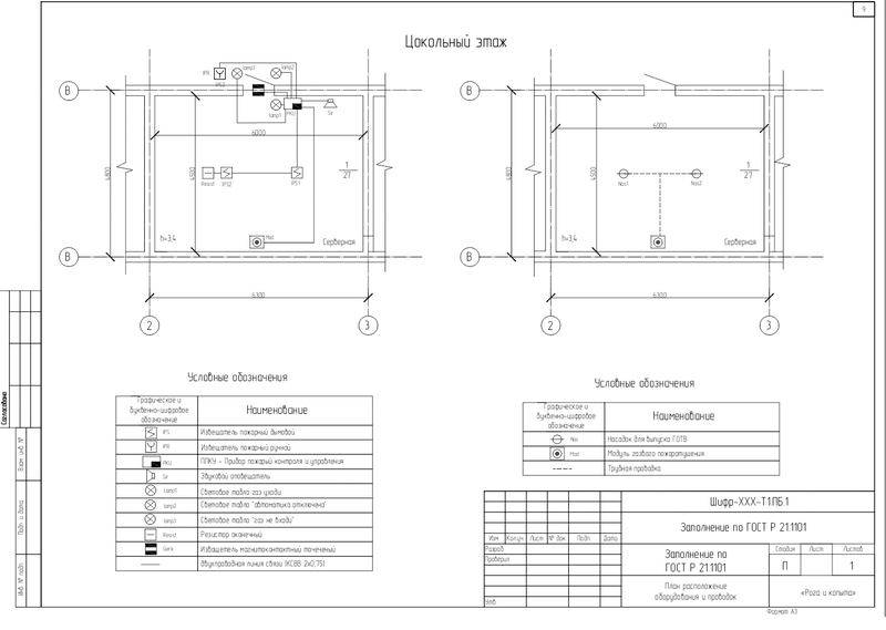
Plan the location of the equipment on it, we show the UGO system elements and their connection with each other. For project documentation, the accuracy of placing the HBO on the plan does not have a cardinal value.
Plan the location of the equipment on it, we show the UGO system elements and their connection with each other. For project documentation, the accuracy of placing the HBO on the plan does not have a cardinal value.
Structural scheme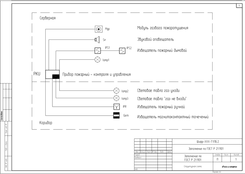
Structural scheme, again the same thing only without reference to the plan.
Structural scheme, again the same thing only without reference to the plan.
Axonometric circuit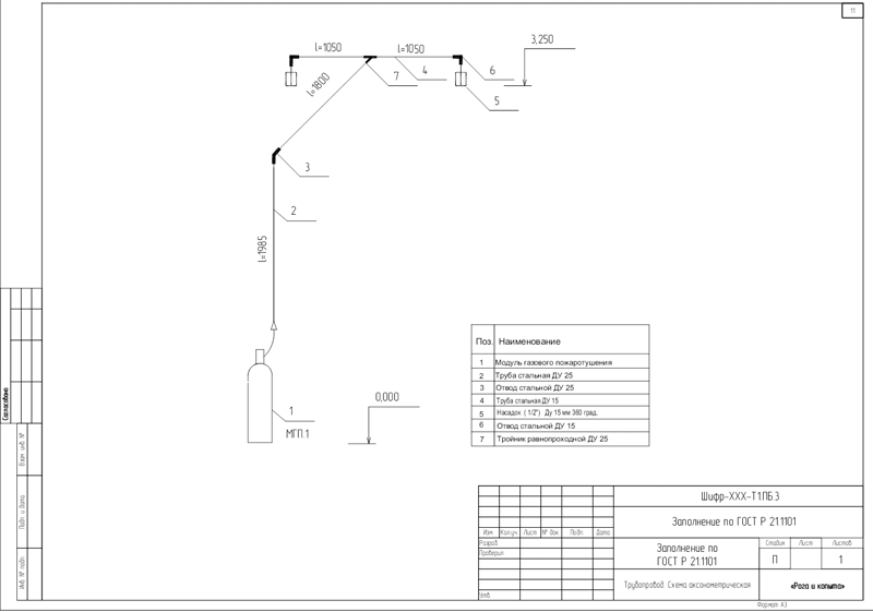
Aconometric (or maybe not) scheme of the pipeline.
This scheme we need to conduct a hydraulic calculation of the installation.
By itself, the hydraulic calculation firstly helps to understand whether our installation will work normally (or the gas will remain in the liquid phase - in the case of freon). Also, the hydraulic calculation helps to select (or check the selected) pipes and gas spray nozzles.
From the schemes go to the calculations.
You can get a hydraulic calculation in three ways (let's go from simple to complex):
Request a calculation from the manufacturer of the equipment. The manufacturer will ask you for a placement plan and axonometric scheme, ask you to fill out an application. And in the end I will send you a hydraulic calculation and maybe immediately TKP. The option is good, reducing risks, lack of only one calculation, you can wait for an unpredictable period of time. This case is good if you chose Novek as the GOTV, because according to my data at the time of writing this article, there are no free programs for performing hydraulic calculations.
Calculate using programs provided by equipment manufacturers. I know of 2 worthwhile programs:
A) The program "Salute"
Interface Screenshots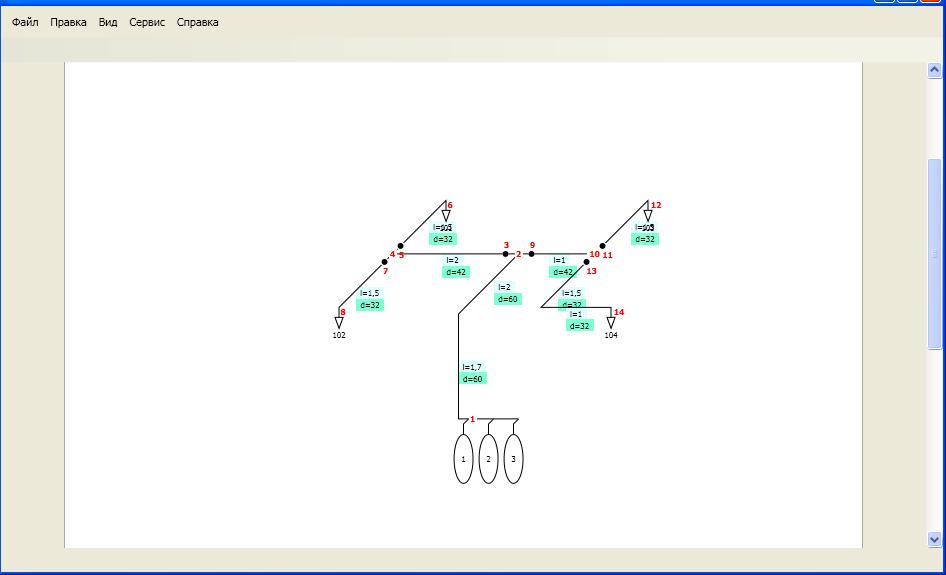
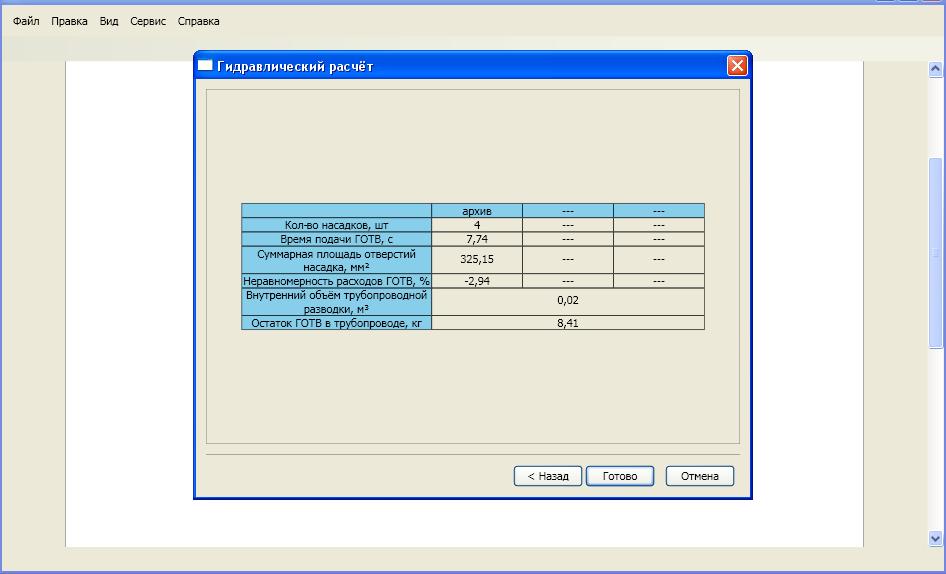
This program is free, can only be used with the equipment of the manufacturer, allows you to calculate the installation for operation on freons: 125, 227 and 2. Despite the free program, the program is not publicly available, you will need to write to the company's support service, there are adequate people there, they will either tell you how to drive up to pick up the disk (I took my own by visiting their stand at the thematic exhibition), or offer another solution, the main thing is to adequately motivate the reason for the request (it is not necessary to write that you just want to play around). For independent design calculations, I would recommend this particular program, the accuracy of calculations is perhaps somewhat lower than that of competitors, but with the help of an intuitive graphical interface you can carry out a full cycle of calculations: from calculating the mass of gas and the opening area for pressure relief to the hydraulic calculation .
Option B)
ZALP Program from ARTSOK
Unfortunately, I don’t have any screenshots at hand, but I hope you will take my word for it. The program is distributed, as well as the previous version, through a request from the manufacturer (they can teach in their office how to use the program).
The program is an executable file running in the command line mode, and a graphical add-in to it, which allows you to generate a source data file.
This program is suitable for experienced professionals, because it will require a higher level of abstraction from you, draw a diagram in a couple of clicks and get the result, as in the previous program in zalp will not work. Firstly, it is necessary in accordance with SP5. Calculate the mass of gas (or search the Internet for an Excel file to automate this process). You will also have to choose the gas parameters and enter them into the program yourself. Secondly, it will be necessary to decompose the pipeline scheme you have drawn up into data in a program format (which is difficult for an inexperienced person). Nevertheless, the program allows you to perform calculations with an upstart accuracy and may well be useful to you if you decide to seriously engage in the design of AUGPT.
3) Option to download the technique and calculate manually
For example, here is this Method TAK GAZ f (there are others)
In this project, I did not make calculations, because they would be tied to the equipment, but the proposed location plan and axonometric scheme are completely entitled to life.
Separately, I want to say why the scheme 2 nozzle.
This is due to the radius of the spray. the average radius of the spray radial nozzle = 3.5 meters. In our case, one nozzle would not cover the entire area of the room. therefore, we applied a symmetrical piping layout.
By the way, do not be confused by the fact that the gas from the pipe with a nominal diameter of 25 is divided into 2 branches of DN 15, in practice this separation is quite acceptable for refrigerants.
Having understood, with directly technical part, we will pass to a part narrative.
I will not describe in detail what needs to be reflected in the text part.
When developing an explanatory note, you should focus on the above regulatory documents and dance directly from the object and the equipment used.
In the annex to the article, there is a draft for the explanatory note and a draft for the specification.
Frankly, I wanted to support the spirit of OpenSource programs and made documents in OpenOffice, but I still could not solve the problem with the numbering of pages within the section, well, there are still a few shortcomings (if someone can fix them I will be glad). In any case, it is quite possible to find frames in MS Office format or make them yourself by analogy. Therefore, I hope that this will not be a big problem.
In conclusion I want to say that this project and all my statements should not be regarded as absolutely correct and infallible (I cannot call myself a guru for the design of AUGP and other engineering systems). I just hope that this article and materials will help in the future to reduce the number of absolutely horrible and stupid projects in the vastness of our vast country.
Files to article
summary * pdf of a very similar project
You can download:
on hosting:
on "Yandex disk":
yadi.sk/d/JLhFzWhAA8Wmy
Useful articles on the design of AUGPT for those who are interested in:
Articles on the design of AUGP from the company "ARTSOK"
Useful presentation of the program "salute" from the company "Fire Automation"
This article does not advertise anything, all links to third-party resources are for informational purposes only.
Upd: Unfortunately, the source code of the project was irretrievably lost, instead of them I attach a pdf summary of a very similar project.
Source: https://habr.com/ru/post/157571/
All Articles