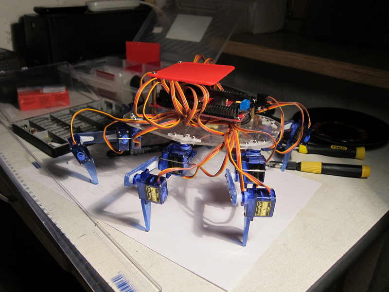
We collect and make run the budget hexapod
There is a lot to be done before we get to this picture:
Dropping rozkazni about how exactly I came up with the idea to build a hexapod (these were tons of videos on YouTube), I’ll go straight to the process of selecting items. It was January 2012. I immediately knew what I want from my robot, and what I do not. I wanted:
')
- each leg should have 3 degrees of freedom - 3dof (3 dimensions of freedom). Because the simpler version of 2dof - does not give such an insect sensation, and 4dof - unnecessarily, 3dof allows you to freely move the tip of the foot in 3D space;
- 6 legs; again, this is no longer 4 (then the robot clumsily jumps), but also not 8, like spiders and already excessively;
- small;
- cheap;
- minimum boards and connections;
Post big.
The first of course was to choose a motherboard for the crumbs. A lot of good and bad had time to read about Arduino by then. But it was him who looked like the main option. It’s time to solder controllers yourself, but to take more advanced boards with ARM cpu, for example, it’s expensive, and to figure out how to program them, how to work with PWM outputs, etc. And arduin: IDE launched, code hit, upload clicked - and hello, it is already blinking. Beauty! ;)
At first I began to look at arduino mega and clones, because number of PWM outputs, which can be serviced by the servos they had plenty. Let me remind you that for 3dof hexapod you need 3 * 6 = 18 servov, and separate control channels. But then I found the real Yazh among the arduino mega, this is a board from Dagu, called Red Back Spider Controller. Here it is on ebay.
It offers all of its outputs in the form of ready-made 3 pins (ground, power, signal), and power distribution. The power of the controller itself is stabilized, and it goes to the dviglov connectors as is (UPD: not as it is, but also stabilized 5 volts. And apparently untied with the power supply of the controller, since they do not interfere with the operation of the controller 18 at the same time). This allows you to simply apply 7-30 volts of sufficient power to the power terminal (the feeder from the eee pc 901 for 12V and 3A turned out to be sufficient for buzzing with all 18 servami) and not fooling around with separate power supply of logic and dviglov. Also, this will allow in the future to easily put all this monster on a pack of Li-Po batteries at 7.4 volts. And with all this, from a software point of view, this is the usual arduino mega, compatible with software and libs, and even with hardware (except for shilds that are installed directly on the original mega - they will not roll). True, the price is even higher than the original mega, but all the other advantages outweighed it.
Next servos. On ebay, on request, micro servo has many different ones. I took the most powerful of the smallest and cheapest, weighing 9 grams, with plastic gearboxes. If you take the lots where they are sent in bundles - it turns out cheaper. I took 3 packs of 6, it seems, and less than $ 2 came out. Looking ahead, I would say that I regret that I did not spend more and did not take servos with metal gears and ball bearings. These plastic ones had quite noticeable backlashes, and a characteristic crunch with excessive force when the gears slip. Because of the backlash - kinematics is quite difficult to adjust accurately (yes it turned out to be the hardest).
That's actually all that I ordered, with the delivery it came out about $ 100. Batteries and transmitters / receivers for control and radio control - left for later. Because I have a radio-controlled machine and it is not interesting, and what really interested me is legs! The video of smoothly walking hexapods on YouTube was fascinating , I watched it, revised it, and each time tears rolled down my cheeks, and I choked out a “I want!” Wheezing. I do not want to order such a finished piece, but I want to do something myself!
While waiting for the order, I read how educated people enliven their creations. Of course, inverse kinematics immediately surfaced ( translation ). If we say simply and immediately about the spherical "limbs", then the direct kinematics is when the angles of the hinges are fed to the input, and at the output we have a model of finiteness in space, and the coordinates of the extreme point of the limb. Inverse kinematics - obviously works the other way around - the coordinates of the extreme point of the limb arrive at the entrance, where we need to reach, and at the exit we get the angles that need to be rotated to make this possible. Servos just get to the entrance of the angular position in which they need to turn (one signal wire, encoded PWM / PWM ).
Started writing. I started with what I read about: think over the implementation of IC using the method described there . But it quickly came to the feeling that for my case it was overly complex. Moreover, it is both cumbersome to implement and computationally very complicated - the calculation is iterative. And I have 6 legs, for each of which you need to consider IR, and only 16 MHz is not the smartest AVR architecture. But only 3 degrees of freedom. And it is easy to guess that it is possible to reach an arbitrary point in the “reach area” only in one way. The decision is already ripe in the head.
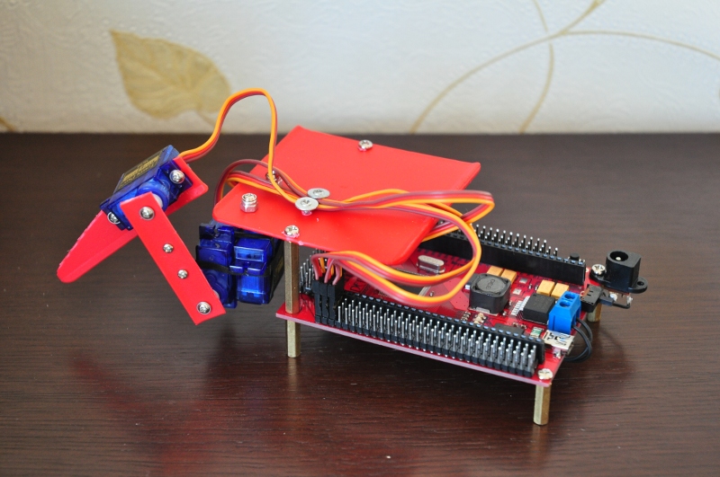
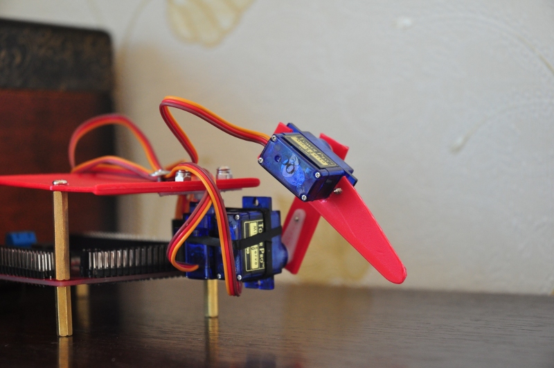
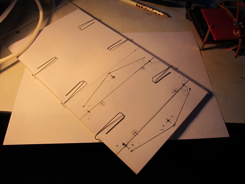
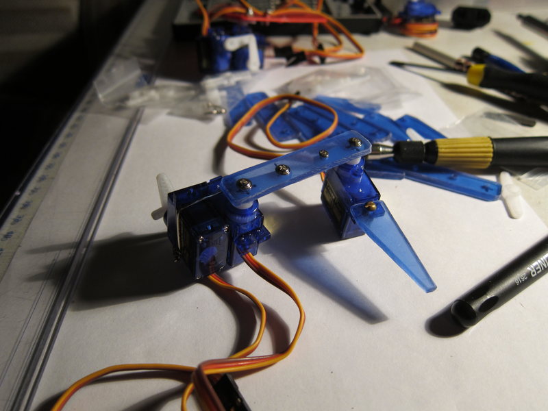
But here came February and the parcel - one from China, the other from UK. First of all, of course, I just played around with the Arduino board - I blinked the LED and populated the speaker connected to it. Then he started selling the actual IC, already in the gland. For which he built a prototype of the legs from the materials at hand (rather soft plastic, which is easy to cut with scissors, screws and nozzles are all from servo sets). Terminator fixed this leg directly to the Arduin board. You can consider how the budget made articulations.
I admired this case and dreamed that if I based on this robot in the future, solder a terminator who will declare war on humanity, then John Connor and Schwarzenegger will return to me here in the past and will select this prototype and melt it in Orodruin. But nobody returned, didn’t take anything away, and I calmly continued.
It turned out that IC does not need to be afraid at all, in my case it all boiled down to banal geometry-trigonometry. To make it easier to turn to the joints, turned to Wikipedia and read about insects. They have special names for limb elements:
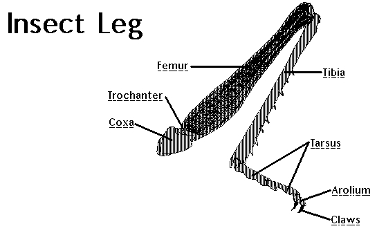
The Russian also has its own and very interesting names for this, but “wash”, “swivel”, “shin”, etc., being in the code, would not let me fall asleep. Therefore, I left the names Coxa, Femur, Tibia to 3 limbs and corresponding servas. From the prototype of the legs above it is clear that I don’t even have a separate part for coxa. These are just two servos held together with rubber bands. Femur - implemented with a strip of plastic, to which servo arms are attached to both sides. Thus, the last remaining servodvik is the beginning of tibia, for which an additional piece of plastic is bolted to it.
Launched the editor, without thinking, created the file Leg.h, and in it the class Leg. Well, a bunch of auxiliary dregs.) Let there be a point A (ax, ay, az) in space to which you need to reach. Then the top view looks like this:
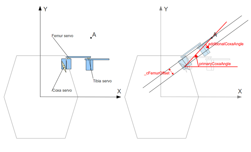
In the figure, I immediately showed a method for calculating the first angle — this is the angle of rotation of the servo that controls Coxa, which rotates the entire limb in the horizontal plane. On the diagram, red immediately indicates the variables used in the code (not all). Not very mathematically, but convenient. It can be seen that the angle of interest is elementary. First, primaryCoxaAngle is simply the angle (0; A) to the X axis (which is equivalent to the angle of point A in polar coordinates). But the diagram shows that in this case the leg itself is not located at this angle. The reason is that the axis of rotation coxa is not on the “foot line” - I don’t know how to say it correctly. It is not in the plane in which the other 2 joints rotate and the tip of the foot is located, here. This can be easily compensated by considering additionalCoxaAngle (how to count it - I don’t even bother to stop, well, after all, they were still at school, right?).
So, we have the first piece of code, it's the insides of the reach (Point & dest) method:
Here dest is the point where you need to go, _cStart is the coordinates of the anchor point (and center of rotation) coxa, in hDist we consider the distance from _cStart to dest in the horizontal plane. DONT_MOVE is just a flag, meaning that coxa does not need to be rotated anywhere, but left in its current position (since dest is somewhere right on the axis of rotation coxa is rare, but it happens). Here cAngle is the angle by which the servo will need to deviate from its starting angle (which is in the middle of its operating range). It can be seen that _cStartAngle is also used - this is the angle in the space that the servo is rotated devalt for during installation. About _thirdQuarterFix I will tell later if I will not forget.
Then everything becomes even easier. We just need to look at the “leg line” plane mentioned above:
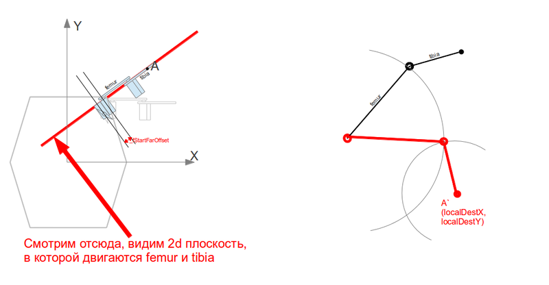
At the same time, the task is suddenly reduced to finding the intersection point of 2 circles. One is at the point where our femur is “growing”, the second is the point where we need to reach (with already local 2d coordinates). The radii of the circles are the lengths of femur and tibia, respectively. If the circles intersect, then a joint can be positioned in one of the 2 points. We always choose the top so that the “knees” of the monster are arched upwards, not downwards. If you do not intersect, then we will not reach the target point. A little more code, the transition to the plane is done elementarily, only a couple of pitfalls are still taken into account and documented in the commentary so that I do not break my head afterwards, disassembling the code. For simplicity, in this local coordinate “plane of the leg” I chose the point where the femur grows:
Now localDestX and localDestY are the coordinates of the target point. All that remains is to find the intersection point of the circles with the centers at (0,0) and (localDestX, localDestY), and the radii _fLength and _tLength (respectively, the length of femur and the length of tibia). The schoolchild will cope with this too, but here I made quite a few mistakes, so to check myself and in general, anyone could check what kind of dumb formulas I had, I left links to sources where this elementary geometric problem is cleared and cleared:
Everything, there is still a little bit - from the coordinates obtained, calculate the proper angles for the femur and tibia servs:
Again elementary - angular coordinates and all. I hope the naming of the variables should already be clear, for example, _fStartAngle is the femur start angle, the angle to which the femur is defaulted. And the last line of the reach () method (he said let's go and waved his hand):
The move method directly gives commands to the servas. In fact, it still had to add all sorts of things in it to protect against bad angles (at which the servo cannot turn, but will try), as well as for other legs that are radically located and / or directed to other sides. But in the meantime, we are working with only one paw.
These pieces are the final code, which is far from perfect, and surely it can be significantly improved. But it works! Without ever going beyond the school course of geometry-trigonometry, we implemented a fully functional inverse kinematics for 3dof legs! Yes, and we get the solution immediately for one iteration. For this to work, the foot needed to be carefully measured, and the class configured with the data obtained. including angular, which is the most difficult to measure on the finished product. Maybe if designing in an autocade and making beautiful renders would be easier with measuring angles, but I had neither the time nor the desire to engage in this pathos.
February has just begun, and the video with the foot was already ready. To check the IR, I forced the foot to describe all sorts of figures in space (for this it was necessary to consistently call reach, bypassing points on a rectangle, or a circle, the code is dull and dull, therefore I do not quote (and having finished the experiments with a circle around the primitives, I cut it out) ):
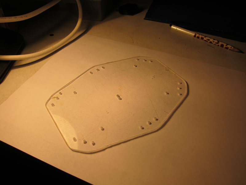
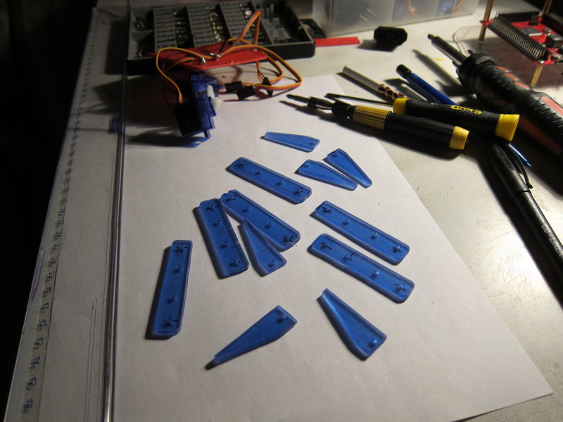
Then it was necessary to finish playing with this hand-made article, on one foot you could not jump far (although such a robot would come out really interesting). But I need a hexapod. Went to the nearest flea market to look for plexiglass. I found 2 excellent pieces - one 3 mm thick (just for the body, I thought), another 2 mm and blue (excellent limbs, in tone with servo drives). After another couple of weeks, I carved out an evening to make something out of it. Made sketches on paper. tried on - like everything is OK, then it's up to the hacksaw.


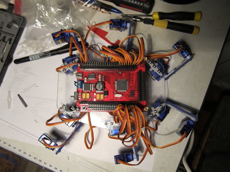
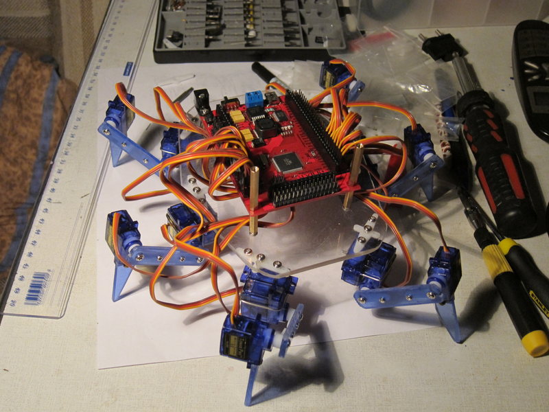
And here it is, a monster overseas, sheshilapoe. When I tested one leg, I fed this business with some kind of left-side feeder from an external screw. Enough. But to feed 6 legs from him was already scary. So I hung up my hands for a while, thinking that I still needed to get a suitable feeder. But it turned out to be much simpler, I already mentioned above - the eee pc 901 feeder came up. Well and good.
Debugging the work of 6 legs was even more difficult than writing the engine of one foot. Half of the legs were mirrored relative to the other. In addition, all are directed in different directions. In general, I configured and configured everything for a very long time, and it didn’t really inspire me, because there were no convenient debugging tools, the most I could count on was logging to Serial. And that one worked normally from the main * .ino file, and from the connected Leg.h - the necessary object was no longer seen. Turn up the crutches for the log (facepalm). In time, I will refactor. And then spring came, the cycle season was open in full force, and I threw my six-pet pet in the closet. So it was all summer and the warm part of autumn.
But it started to rain, it became cold, and the hexapod was removed. His legs were debugged, including the very _thirdQuarterFix was introduced for the polarAngle calculation function. The problem was that 2 legs (left middle and left back) moved so that most of the time were in the third quarter:
And polarAngle was naive for me - it returned angles from pi to pi, relative to the X axis. And if sometimes one of these 2 legs needed to turn in the 2nd quarter, then the polarAngle value jumped from pi to pi what actually negatively influenced the further calculation. Fixed a crutch - for these 2 legs the polarAngle is considered "different." I’m ashamed, I’m ashamed of the code, but the whole project is proof of concept, the only purpose of which is just to understand, can I put together a realistic hexpod or not. Because the code should work, and right now. And then refactoring - re-factoring.
Having coped with the 3rd quarter, I started pedaling the step patterns. For this, I introduced the default point in the Leg class, i.e. in which the leg is located when the robot is standing quietly and evenly. This point can be tuned, the main thing is that all the legs are on the same z coordinate (so that the legs are actually physically on the same plane, Leg has the lowest level tuneRestAngles ()). And within the same Z coordinates, they can be moved almost as desired. Almost - because the range of motion is not infinite, and so as not to go beyond this range when walking - the default position of the legs tried to be placed somewhere closer to the center of this range.
The code here in the text is no longer cited, it is too elementary, and at the end I will cite links to the full version of all sorts - at the same time I will learn to use github.
The sequence of the step chose a simple one - 3 legs on the ground, 3 - are rearranged in the air. Thus, the coordinates of the legs relative to their default position can be divided into 2 groups. For these two groups, I turned the step in the loop (see the walk () function in Buggy.ino). As a result, each leg calculated its own individual coordinate, based on its default coordinates.
And he went! But so far only forward. He put gum on his feet so that he did not slide on linoleum so much. And rushed to shoot it on video to show friends.
To a-poda, of course, far away. But I haven’t finished yet.) I pidalced another evening - and added the ability to move in any direction (but not turning the body.)). Plus, for smoothing between movements, added a function (smoothTo ()), which gently moves the legs (lifting up, again in 2 groups, one of which is always below, the creature stands on it while the other rises and moves) to a new position. It is necessary that the creature does not jerk sharply with their feet, changing the direction of movement (oh, this feature is not enough for many game characters of the past years). And he quickly ran in any direction - sideways, diagonally:
Both grand files of sorts can be viewed here . I give a link to a specific revision, at the time of this writing. Since in the future everything can be very different.
The results that so far can be highlighted:
- to rivet the hexapod itself is a workable thing;
- write him the kinematics himself from scratch - also quite capable of any (the developer);
- the budget may be minimal, the only thing that really needs to be spent is the servos; and so, if there is a soldering iron, then you can do with any microcontroller; the more convenient, the more expensive, however;
- it is better not to save on servah, but the cheapest ones work;
- I have not experienced such a pleasure from programming since I was 9 when I first saw the zx spectrum computer circle and learned how to write the first programs for it; it's so cool when your code doesn't just work somewhere and shows something to someone, but runs right in front of you and scares the cat.
There are more advanced algorithms ahead for smooth body movement, and of course, wireless controls and batteries, of course.
Dropping rozkazni about how exactly I came up with the idea to build a hexapod (these were tons of videos on YouTube), I’ll go straight to the process of selecting items. It was January 2012. I immediately knew what I want from my robot, and what I do not. I wanted:
')
- each leg should have 3 degrees of freedom - 3dof (3 dimensions of freedom). Because the simpler version of 2dof - does not give such an insect sensation, and 4dof - unnecessarily, 3dof allows you to freely move the tip of the foot in 3D space;
- 6 legs; again, this is no longer 4 (then the robot clumsily jumps), but also not 8, like spiders and already excessively;
- small;
- cheap;
- minimum boards and connections;
Post big.
The first of course was to choose a motherboard for the crumbs. A lot of good and bad had time to read about Arduino by then. But it was him who looked like the main option. It’s time to solder controllers yourself, but to take more advanced boards with ARM cpu, for example, it’s expensive, and to figure out how to program them, how to work with PWM outputs, etc. And arduin: IDE launched, code hit, upload clicked - and hello, it is already blinking. Beauty! ;)
At first I began to look at arduino mega and clones, because number of PWM outputs, which can be serviced by the servos they had plenty. Let me remind you that for 3dof hexapod you need 3 * 6 = 18 servov, and separate control channels. But then I found the real Yazh among the arduino mega, this is a board from Dagu, called Red Back Spider Controller. Here it is on ebay.
It offers all of its outputs in the form of ready-made 3 pins (ground, power, signal), and power distribution. The power of the controller itself is stabilized, and it goes to the dviglov connectors as is (UPD: not as it is, but also stabilized 5 volts. And apparently untied with the power supply of the controller, since they do not interfere with the operation of the controller 18 at the same time). This allows you to simply apply 7-30 volts of sufficient power to the power terminal (the feeder from the eee pc 901 for 12V and 3A turned out to be sufficient for buzzing with all 18 servami) and not fooling around with separate power supply of logic and dviglov. Also, this will allow in the future to easily put all this monster on a pack of Li-Po batteries at 7.4 volts. And with all this, from a software point of view, this is the usual arduino mega, compatible with software and libs, and even with hardware (except for shilds that are installed directly on the original mega - they will not roll). True, the price is even higher than the original mega, but all the other advantages outweighed it.
Next servos. On ebay, on request, micro servo has many different ones. I took the most powerful of the smallest and cheapest, weighing 9 grams, with plastic gearboxes. If you take the lots where they are sent in bundles - it turns out cheaper. I took 3 packs of 6, it seems, and less than $ 2 came out. Looking ahead, I would say that I regret that I did not spend more and did not take servos with metal gears and ball bearings. These plastic ones had quite noticeable backlashes, and a characteristic crunch with excessive force when the gears slip. Because of the backlash - kinematics is quite difficult to adjust accurately (yes it turned out to be the hardest).
That's actually all that I ordered, with the delivery it came out about $ 100. Batteries and transmitters / receivers for control and radio control - left for later. Because I have a radio-controlled machine and it is not interesting, and what really interested me is legs! The video of smoothly walking hexapods on YouTube was fascinating , I watched it, revised it, and each time tears rolled down my cheeks, and I choked out a “I want!” Wheezing. I do not want to order such a finished piece, but I want to do something myself!
While waiting for the order, I read how educated people enliven their creations. Of course, inverse kinematics immediately surfaced ( translation ). If we say simply and immediately about the spherical "limbs", then the direct kinematics is when the angles of the hinges are fed to the input, and at the output we have a model of finiteness in space, and the coordinates of the extreme point of the limb. Inverse kinematics - obviously works the other way around - the coordinates of the extreme point of the limb arrive at the entrance, where we need to reach, and at the exit we get the angles that need to be rotated to make this possible. Servos just get to the entrance of the angular position in which they need to turn (one signal wire, encoded PWM / PWM ).
Started writing. I started with what I read about: think over the implementation of IC using the method described there . But it quickly came to the feeling that for my case it was overly complex. Moreover, it is both cumbersome to implement and computationally very complicated - the calculation is iterative. And I have 6 legs, for each of which you need to consider IR, and only 16 MHz is not the smartest AVR architecture. But only 3 degrees of freedom. And it is easy to guess that it is possible to reach an arbitrary point in the “reach area” only in one way. The decision is already ripe in the head.
But here came February and the parcel - one from China, the other from UK. First of all, of course, I just played around with the Arduino board - I blinked the LED and populated the speaker connected to it. Then he started selling the actual IC, already in the gland. For which he built a prototype of the legs from the materials at hand (rather soft plastic, which is easy to cut with scissors, screws and nozzles are all from servo sets). Terminator fixed this leg directly to the Arduin board. You can consider how the budget made articulations.
I admired this case and dreamed that if I based on this robot in the future, solder a terminator who will declare war on humanity, then John Connor and Schwarzenegger will return to me here in the past and will select this prototype and melt it in Orodruin. But nobody returned, didn’t take anything away, and I calmly continued.
It turned out that IC does not need to be afraid at all, in my case it all boiled down to banal geometry-trigonometry. To make it easier to turn to the joints, turned to Wikipedia and read about insects. They have special names for limb elements:
The Russian also has its own and very interesting names for this, but “wash”, “swivel”, “shin”, etc., being in the code, would not let me fall asleep. Therefore, I left the names Coxa, Femur, Tibia to 3 limbs and corresponding servas. From the prototype of the legs above it is clear that I don’t even have a separate part for coxa. These are just two servos held together with rubber bands. Femur - implemented with a strip of plastic, to which servo arms are attached to both sides. Thus, the last remaining servodvik is the beginning of tibia, for which an additional piece of plastic is bolted to it.
Launched the editor, without thinking, created the file Leg.h, and in it the class Leg. Well, a bunch of auxiliary dregs.) Let there be a point A (ax, ay, az) in space to which you need to reach. Then the top view looks like this:
In the figure, I immediately showed a method for calculating the first angle — this is the angle of rotation of the servo that controls Coxa, which rotates the entire limb in the horizontal plane. On the diagram, red immediately indicates the variables used in the code (not all). Not very mathematically, but convenient. It can be seen that the angle of interest is elementary. First, primaryCoxaAngle is simply the angle (0; A) to the X axis (which is equivalent to the angle of point A in polar coordinates). But the diagram shows that in this case the leg itself is not located at this angle. The reason is that the axis of rotation coxa is not on the “foot line” - I don’t know how to say it correctly. It is not in the plane in which the other 2 joints rotate and the tip of the foot is located, here. This can be easily compensated by considering additionalCoxaAngle (how to count it - I don’t even bother to stop, well, after all, they were still at school, right?).
So, we have the first piece of code, it's the insides of the reach (Point & dest) method:
float hDist = sqrt( sqr(dest.x - _cStart.x) + sqr(dest.y - _cStart.y) ); float additionalCoxaAngle = hDist == 0.0 ? DONT_MOVE : asin( _cFemurOffset / hDist ); float primaryCoxaAngle = polarAngle(dest.x - _cStart.x, dest.y - _cStart.y, _thirdQuarterFix); float cAngle = hDist == 0.0 ? DONT_MOVE : primaryCoxaAngle - additionalCoxaAngle - _cStartAngle; Here dest is the point where you need to go, _cStart is the coordinates of the anchor point (and center of rotation) coxa, in hDist we consider the distance from _cStart to dest in the horizontal plane. DONT_MOVE is just a flag, meaning that coxa does not need to be rotated anywhere, but left in its current position (since dest is somewhere right on the axis of rotation coxa is rare, but it happens). Here cAngle is the angle by which the servo will need to deviate from its starting angle (which is in the middle of its operating range). It can be seen that _cStartAngle is also used - this is the angle in the space that the servo is rotated devalt for during installation. About _thirdQuarterFix I will tell later if I will not forget.
Then everything becomes even easier. We just need to look at the “leg line” plane mentioned above:
At the same time, the task is suddenly reduced to finding the intersection point of 2 circles. One is at the point where our femur is “growing”, the second is the point where we need to reach (with already local 2d coordinates). The radii of the circles are the lengths of femur and tibia, respectively. If the circles intersect, then a joint can be positioned in one of the 2 points. We always choose the top so that the “knees” of the monster are arched upwards, not downwards. If you do not intersect, then we will not reach the target point. A little more code, the transition to the plane is done elementarily, only a couple of pitfalls are still taken into account and documented in the commentary so that I do not break my head afterwards, disassembling the code. For simplicity, in this local coordinate “plane of the leg” I chose the point where the femur grows:
// Moving to local Coxa-Femur-target coordinate system // Note the case when hDist <= _cFemurOffset. This is for the blind zone. // We never can't reach the point that is nearer to the _cStart then // femur offset (_fStartFarOffset) float localDestX = hDist <= _cFemurOffset ? - _fStartFarOffset : sqrt(sqr(hDist) - sqr(_cFemurOffset)) - _fStartFarOffset; float localDestY = dest.z - _fStartZOffset; // Check reachability float localDistSqr = sqr(localDestX) + sqr(localDestY); if (localDistSqr > sqr(_fLength + _tLenght)) { log("Can't reach!"); return false; } Now localDestX and localDestY are the coordinates of the target point. All that remains is to find the intersection point of the circles with the centers at (0,0) and (localDestX, localDestY), and the radii _fLength and _tLength (respectively, the length of femur and the length of tibia). The schoolchild will cope with this too, but here I made quite a few mistakes, so to check myself and in general, anyone could check what kind of dumb formulas I had, I left links to sources where this elementary geometric problem is cleared and cleared:
// Find joint as circle intersect ( equations from http://e-maxx.ru/algo/circles_intersection & http://e-maxx.ru/algo/circle_line_intersection ) float A = -2 * localDestX; float B = -2 * localDestY; float C = sqr(localDestX) + sqr(localDestY) + sqr(_fLength) - sqr(_tLenght); float X0 = -A * C / (sqr(A) + sqr(B)); float Y0 = -B * C / (sqr(A) + sqr(B)); float D = sqrt( sqr(_fLength) - (sqr(C) / (sqr(A) + sqr(B))) ); float mult = sqrt ( sqr(D) / (sqr(A) + sqr(B))); float ax, ay, bx, by; ax = X0 + B * mult; bx = X0 - B * mult; ay = Y0 - A * mult; by = Y0 + A * mult; // Select solution on top as joint float jointLocalX = (ax > bx) ? ax : bx; float jointLocalY = (ax > bx) ? ay : by; Everything, there is still a little bit - from the coordinates obtained, calculate the proper angles for the femur and tibia servs:
float primaryFemurAngle = polarAngle(jointLocalX, jointLocalY, false); float fAngle = primaryFemurAngle - _fStartAngle; float primaryTibiaAngle = polarAngle(localDestX - jointLocalX, localDestY - jointLocalY, false); float tAngle = (primaryTibiaAngle - fAngle) - _tStartAngle; Again elementary - angular coordinates and all. I hope the naming of the variables should already be clear, for example, _fStartAngle is the femur start angle, the angle to which the femur is defaulted. And the last line of the reach () method (he said let's go and waved his hand):
move(cAngle, fAngle, tAngle); The move method directly gives commands to the servas. In fact, it still had to add all sorts of things in it to protect against bad angles (at which the servo cannot turn, but will try), as well as for other legs that are radically located and / or directed to other sides. But in the meantime, we are working with only one paw.
These pieces are the final code, which is far from perfect, and surely it can be significantly improved. But it works! Without ever going beyond the school course of geometry-trigonometry, we implemented a fully functional inverse kinematics for 3dof legs! Yes, and we get the solution immediately for one iteration. For this to work, the foot needed to be carefully measured, and the class configured with the data obtained. including angular, which is the most difficult to measure on the finished product. Maybe if designing in an autocade and making beautiful renders would be easier with measuring angles, but I had neither the time nor the desire to engage in this pathos.
February has just begun, and the video with the foot was already ready. To check the IR, I forced the foot to describe all sorts of figures in space (for this it was necessary to consistently call reach, bypassing points on a rectangle, or a circle, the code is dull and dull, therefore I do not quote (and having finished the experiments with a circle around the primitives, I cut it out) ):
Then it was necessary to finish playing with this hand-made article, on one foot you could not jump far (although such a robot would come out really interesting). But I need a hexapod. Went to the nearest flea market to look for plexiglass. I found 2 excellent pieces - one 3 mm thick (just for the body, I thought), another 2 mm and blue (excellent limbs, in tone with servo drives). After another couple of weeks, I carved out an evening to make something out of it. Made sketches on paper. tried on - like everything is OK, then it's up to the hacksaw.
And here it is, a monster overseas, sheshilapoe. When I tested one leg, I fed this business with some kind of left-side feeder from an external screw. Enough. But to feed 6 legs from him was already scary. So I hung up my hands for a while, thinking that I still needed to get a suitable feeder. But it turned out to be much simpler, I already mentioned above - the eee pc 901 feeder came up. Well and good.
Debugging the work of 6 legs was even more difficult than writing the engine of one foot. Half of the legs were mirrored relative to the other. In addition, all are directed in different directions. In general, I configured and configured everything for a very long time, and it didn’t really inspire me, because there were no convenient debugging tools, the most I could count on was logging to Serial. And that one worked normally from the main * .ino file, and from the connected Leg.h - the necessary object was no longer seen. Turn up the crutches for the log (facepalm). In time, I will refactor. And then spring came, the cycle season was open in full force, and I threw my six-pet pet in the closet. So it was all summer and the warm part of autumn.
But it started to rain, it became cold, and the hexapod was removed. His legs were debugged, including the very _thirdQuarterFix was introduced for the polarAngle calculation function. The problem was that 2 legs (left middle and left back) moved so that most of the time were in the third quarter:
And polarAngle was naive for me - it returned angles from pi to pi, relative to the X axis. And if sometimes one of these 2 legs needed to turn in the 2nd quarter, then the polarAngle value jumped from pi to pi what actually negatively influenced the further calculation. Fixed a crutch - for these 2 legs the polarAngle is considered "different." I’m ashamed, I’m ashamed of the code, but the whole project is proof of concept, the only purpose of which is just to understand, can I put together a realistic hexpod or not. Because the code should work, and right now. And then refactoring - re-factoring.
Having coped with the 3rd quarter, I started pedaling the step patterns. For this, I introduced the default point in the Leg class, i.e. in which the leg is located when the robot is standing quietly and evenly. This point can be tuned, the main thing is that all the legs are on the same z coordinate (so that the legs are actually physically on the same plane, Leg has the lowest level tuneRestAngles ()). And within the same Z coordinates, they can be moved almost as desired. Almost - because the range of motion is not infinite, and so as not to go beyond this range when walking - the default position of the legs tried to be placed somewhere closer to the center of this range.
The code here in the text is no longer cited, it is too elementary, and at the end I will cite links to the full version of all sorts - at the same time I will learn to use github.
The sequence of the step chose a simple one - 3 legs on the ground, 3 - are rearranged in the air. Thus, the coordinates of the legs relative to their default position can be divided into 2 groups. For these two groups, I turned the step in the loop (see the walk () function in Buggy.ino). As a result, each leg calculated its own individual coordinate, based on its default coordinates.
And he went! But so far only forward. He put gum on his feet so that he did not slide on linoleum so much. And rushed to shoot it on video to show friends.
To a-poda, of course, far away. But I haven’t finished yet.) I pidalced another evening - and added the ability to move in any direction (but not turning the body.)). Plus, for smoothing between movements, added a function (smoothTo ()), which gently moves the legs (lifting up, again in 2 groups, one of which is always below, the creature stands on it while the other rises and moves) to a new position. It is necessary that the creature does not jerk sharply with their feet, changing the direction of movement (oh, this feature is not enough for many game characters of the past years). And he quickly ran in any direction - sideways, diagonally:
Both grand files of sorts can be viewed here . I give a link to a specific revision, at the time of this writing. Since in the future everything can be very different.
The results that so far can be highlighted:
- to rivet the hexapod itself is a workable thing;
- write him the kinematics himself from scratch - also quite capable of any (the developer);
- the budget may be minimal, the only thing that really needs to be spent is the servos; and so, if there is a soldering iron, then you can do with any microcontroller; the more convenient, the more expensive, however;
- it is better not to save on servah, but the cheapest ones work;
- I have not experienced such a pleasure from programming since I was 9 when I first saw the zx spectrum computer circle and learned how to write the first programs for it; it's so cool when your code doesn't just work somewhere and shows something to someone, but runs right in front of you and scares the cat.
There are more advanced algorithms ahead for smooth body movement, and of course, wireless controls and batteries, of course.
Source: https://habr.com/ru/post/156579/
All Articles