MPLS VPN with TE in corporate networks
Good day to all. At first, I wanted to write an “academic” introductory paragraph about why MPLS with all its modern applications is needed. But then I thought that there is a lot of different literature on this subject and “there’s no need to produce another essence here” (William Ockham). Therefore, more to the point.
Even in 2007, the elder Compella (who Kirietti, author of draft-kompella, rfc 6624, and others) told us at the next conference: “Guys, MPLS will be in your home routers soon”. And then end-to-end QoS, TE ... Since then, five years have passed, MPLS has not yet reached home routers, but from the provider technology stepped confidently into the corporate sector. I don’t speak here about large companies where MPLS appeared almost together with provider networks. I mean the medium (and sometimes small) corporate sector, where MPLS networks are actively developing, which is especially noticeable in foreign companies.
The question may arise - why? What is not suitable for ordinary IGP, and sometimes just “stretched in physics” L2? Generally speaking, in my opinion, this is a logical simplicity, if you like, beauty and efficiency of MPLS-based solutions. With the advent of MPLS support for entry-level devices from different manufacturers, it became possible to make elegant and inexpensive solutions that, however, have wide functionality and development potential. MPLS has ceased to be the technology of the "big" and "chosen", from something obscure and inaccessible, it gradually turns into a commodity.
')
What do most often in the corporate sector with MPLS? Basically the same as in the providers, adjusted for the scale - L2 & L3 VPNs, VPLS, plus their protection and provision of QoS based on TE. This article describes a simple example of how to build MPLS VPNs, VPLS based on HP 5800 series devices and protect them using TE mechanisms. Here is the network:
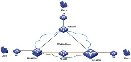
It has three PEs (Provider Edge, attached to the corporate sector, aggregation level), one P (Provider, core) and three CE (Customer Edge, three office networks).
First we raise the base MPLS and the LDP (or MPBGP) signaling to PE. In order not to stretch the article, let me skip the basic settings, like the IGP / BGP settings in the backbone. Since we will continue using TE, we will make MPLS settings immediately with TE support, like this:
Do not forget to include in the OSPF backbone support for Opaque LSA with this “opaque-capability enable” command in order for TE to work. If MBGP is used as an alarm, then BGP peering needs to be raised between PEs and the necessary Name (Address Families) support should be included in BGP. In our example, we will use VPLS and L3 VPN, respectively, we support them and configure them, like this:
Then on PE we raise and bind to the interfaces services. In our case, as I said, these are VPLS and L3 VPNs. Configure L3 VPN Instance (vpn1 in our example) and VPLS VSI (vlan103, 104 in our example) and bind L3 VPN to the VLAN interface, and VPLS to the BA (BridgeAggregation) interface (since the CE comes to PE aggregated channel) , like this:
In L3 VPN, in order not to produce “static”, between CE and PE we raise OSPF and “redistribute” routes with OSPF CE-PE (ospf 201 in our example) in BGP, in order to see them on other sites. On the other side, we perform the reverse operation, “take out” the routes from BGP and “put” them into client-side OSPF, like this:
I will not give you the settings for CE, CE is configured as a router, I don’t know anything about MPLS.
And at the end, to protect against falling channels, set up TE. In order not to overload the example, we will configure one tunnel to protect VSI vlan104 and protect it in two ways. We will prescribe the paths with our hands and then assign a secure tunnel to the service via tunnel-policy and pw-class, like this:
Now, in the case of the fall of the main path, all traffic inside the VSI vlan104 will automatically “move” to the backup route built around the failed one. The result is this picture:
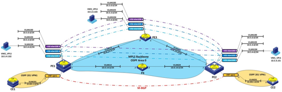
Between the sites are configured transparent for CE L3 VPN and protected with TE VPLS VSI with 104 VLAN encapsulated in it (also transparent for CE). I did not give the P-router configurations (P4 in the picture), since there is only basic MPLS with TE support, the services on it are not terminated, respectively, there are no special settings.
Even in 2007, the elder Compella (who Kirietti, author of draft-kompella, rfc 6624, and others) told us at the next conference: “Guys, MPLS will be in your home routers soon”. And then end-to-end QoS, TE ... Since then, five years have passed, MPLS has not yet reached home routers, but from the provider technology stepped confidently into the corporate sector. I don’t speak here about large companies where MPLS appeared almost together with provider networks. I mean the medium (and sometimes small) corporate sector, where MPLS networks are actively developing, which is especially noticeable in foreign companies.
The question may arise - why? What is not suitable for ordinary IGP, and sometimes just “stretched in physics” L2? Generally speaking, in my opinion, this is a logical simplicity, if you like, beauty and efficiency of MPLS-based solutions. With the advent of MPLS support for entry-level devices from different manufacturers, it became possible to make elegant and inexpensive solutions that, however, have wide functionality and development potential. MPLS has ceased to be the technology of the "big" and "chosen", from something obscure and inaccessible, it gradually turns into a commodity.
')
What do most often in the corporate sector with MPLS? Basically the same as in the providers, adjusted for the scale - L2 & L3 VPNs, VPLS, plus their protection and provision of QoS based on TE. This article describes a simple example of how to build MPLS VPNs, VPLS based on HP 5800 series devices and protect them using TE mechanisms. Here is the network:
It has three PEs (Provider Edge, attached to the corporate sector, aggregation level), one P (Provider, core) and three CE (Customer Edge, three office networks).
First we raise the base MPLS and the LDP (or MPBGP) signaling to PE. In order not to stretch the article, let me skip the basic settings, like the IGP / BGP settings in the backbone. Since we will continue using TE, we will make MPLS settings immediately with TE support, like this:
mpls lsr-id 1.1.1.1 # mpls mpls te mpls te timer fast-reroute 5 mpls rsvp-te mpls te cspf # mpls lspv mpls ldp graceful-restart # mpls ldp remote-peer pe2 remote-ip 2.2.2.2 # mpls ldp remote-peer pe3 remote-ip 3.3.3.3 interface Vlan-interface13 description * to PE3 Vlan13 * ip address 10.0.13.1 255.255.255.0 ospf cost 50 mpls mpls te mpls ldp Do not forget to include in the OSPF backbone support for Opaque LSA with this “opaque-capability enable” command in order for TE to work. If MBGP is used as an alarm, then BGP peering needs to be raised between PEs and the necessary Name (Address Families) support should be included in BGP. In our example, we will use VPLS and L3 VPN, respectively, we support them and configure them, like this:
... bgp 100 ... undo synchronization graceful-restart peer 2.2.2.2 as-number 100 peer 3.3.3.3 as-number 100 peer 2.2.2.2 connect-interface LoopBack0 peer 3.3.3.3 connect-interface LoopBack0 ... # ... vpls-family peer 2.2.2.2 enable peer 3.3.3.3 enable # ipv4-family vpn-instance vpn1 import-route direct import-route ospf 201 # ipv4-family vpnv4 peer 2.2.2.2 enable peer 3.3.3.3 enable Then on PE we raise and bind to the interfaces services. In our case, as I said, these are VPLS and L3 VPNs. Configure L3 VPN Instance (vpn1 in our example) and VPLS VSI (vlan103, 104 in our example) and bind L3 VPN to the VLAN interface, and VPLS to the BA (BridgeAggregation) interface (since the CE comes to PE aggregated channel) , like this:
... ip vpn-instance vpn1 route-distinguisher 201:1 vpn-target 201:1 export-extcommunity vpn-target 201:1 import-extcommunity ... vsi vlan103 auto pwsignal bgp route-distinguisher 103:1 vpn-target 103:1 import-extcommunity vpn-target 103:1 export-extcommunity site 1 range 20 default-offset 0 # vsi vlan104 static pwsignal ldp vsi-id 104 peer 2.2.2.2 pw-class frr peer 3.3.3.3 ... interface Bridge-Aggregation1 description * to CE1 BAGG1 * port link-type trunk undo port trunk permit vlan 1 port trunk permit vlan 100 to 110 201 to 202 link-aggregation mode dynamic stp disable ... service-instance 103 encapsulation s-vid 103 xconnect vsi vlan103 service-instance 104 encapsulation s-vid 104 xconnect vsi vlan104 ... interface Vlan-interface201 ip binding vpn-instance vpn1 ip address 10.201.1.1 255.255.255.0 In L3 VPN, in order not to produce “static”, between CE and PE we raise OSPF and “redistribute” routes with OSPF CE-PE (ospf 201 in our example) in BGP, in order to see them on other sites. On the other side, we perform the reverse operation, “take out” the routes from BGP and “put” them into client-side OSPF, like this:
... bgp 100 ... # ipv4-family vpn-instance vpn1 import-route direct import-route ospf 201 # ... ospf 201 router-id 1.1.1.1 vpn-instance vpn1 import-route bgp silent-interface all undo silent-interface Vlan-interface201 area 0.0.0.0 network 0.0.0.0 255.255.255.255 ... I will not give you the settings for CE, CE is configured as a router, I don’t know anything about MPLS.
And at the end, to protect against falling channels, set up TE. In order not to overload the example, we will configure one tunnel to protect VSI vlan104 and protect it in two ways. We will prescribe the paths with our hands and then assign a secure tunnel to the service via tunnel-policy and pw-class, like this:
... # explicit-path by-path next hop 10.0.13.2 next hop 10.0.23.1 next hop 2.2.2.2 # explicit-path pri-path next hop 10.0.14.2 next hop 10.0.24.1 next hop 2.2.2.2 # ... tunnel-policy policy1 tunnel select-seq cr-lsp load-balance-number 1 # pw-class frr pw-tunnel-policy policy1 ... vsi vlan104 static pwsignal ldp vsi-id 104 peer 2.2.2.2 pw-class frr peer 3.3.3.3 ... interface Tunnel10 ip address 10.1.1.1 255.255.255.0 tunnel-protocol mpls te destination 2.2.2.2 mpls te tunnel-id 10 mpls te record-route label mpls te path explicit-path pri-path preference 1 mpls te path explicit-path by-path preference 2 mpls te path dynamic preference 3 mpls te commit # ... Now, in the case of the fall of the main path, all traffic inside the VSI vlan104 will automatically “move” to the backup route built around the failed one. The result is this picture:
Between the sites are configured transparent for CE L3 VPN and protected with TE VPLS VSI with 104 VLAN encapsulated in it (also transparent for CE). I did not give the P-router configurations (P4 in the picture), since there is only basic MPLS with TE support, the services on it are not terminated, respectively, there are no special settings.
Source: https://habr.com/ru/post/156533/
All Articles