The implementation of the idea of a wireless level gauge
 In the process of working with the installation, the task appeared to make the level gauge in the tanks, since there were occasional overflows, and when 8-10 tons of water are in the basement, which was once a pool for testing torpedoes, then pulling it all into buckets on the third floor is a very difficult task. It would seem that there is nothing special in the task, but several difficulties have appeared.
Conditions:
- Volume of tanks: 2 to 8,000 liters
- Geographic position of tanks: -2nd floor (8 meters underground)
- Floor overlappings: wood
- Required level accuracy: ± 10 liters
- Critical Level Warning
- Indication in the workplace
Analog option
The option with probes in extreme positions disappeared immediately, due to the lack of information about the current level. The first idea was the implementation on the analog principle of the comparator. The basis is LM3915N-1, which is mainly used for logarithmic indicators in acoustics. Scheme - nowhere easier.')
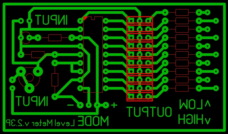
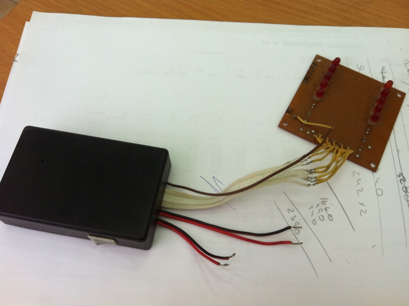
Level output - a point or a column on the line of LEDs. The board shows one shoulder of the voltage divider, which set the initial level.
As a measuring element, a chain of resistors with a length of one and a half meters was made, it was also the second divider arm at the input of the mikruhi. The values of the resistors were chosen so that the output voltage varied from 2 to 5 V, required by the datasheet for the LM. The chain is immersed in the tube for visual inspection along the tank. Connection with the "probe" - 15 meters of a two-wire cable.
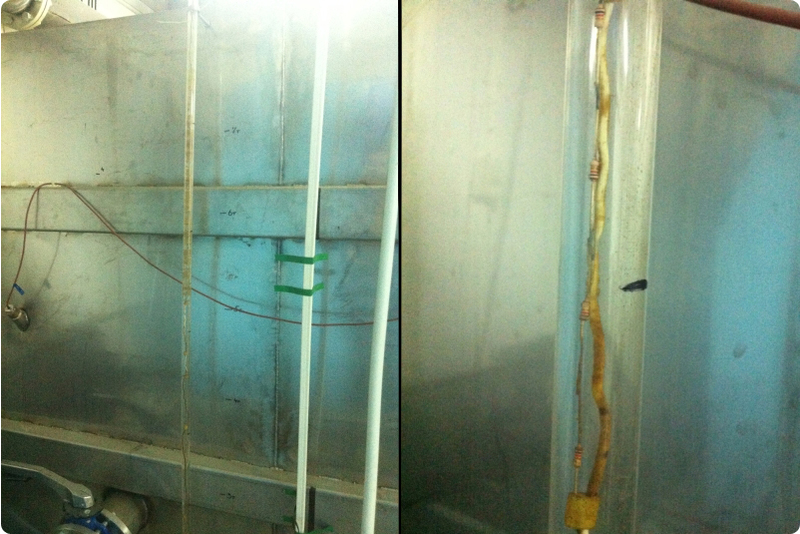
The principle of the idea was that when the resistors were flooded, some of them would close with water, respectively, the voltage at the input of the comparator would increase, the LED bar would be filled. The advantages of this idea lie in the speed of implementation and simplicity, a minus of this light collective farm got out in two or three weeks. The level on the indicator began to gradually fall, and the level in the tank was normal. Trimmer I summed it up to normal, until the design stopped working at all. The reason turned out to be transparent, but it had not previously been possible to guess. The solder of the chain of resistors underwent major electrolysis and the salts of water simply gnawed it in several places. The solution to this disgrace is only a float with a magnet and a reed switch for each link or pile of Hall sensors that would close the “probe” links, but this even larger collective farm and the complexity of the design would obviously increase with the same weak discreteness and accuracy. The scheme was dismantled.
Back to the old drawing board.
As a new implementation, I decided to make a device on the controller. Arduino and analogues do not use in principle, it is more interesting to do everything from scratch, although you can learn something. I work with controllers a little, a year and a half maximum, so I try to learn something new in each development, which means that it would be possible to get by with much cheaper elements (display, connection), but less interesting. Also, do not kick much for implementation and code.A new idea is to use an ultrasonic rangefinder, measure the distance to the water surface, and since tank sizes are known, then the volume to calculate - the task of the simplest.
Components:
- Display: 128x64 graphic NoName with ebay
- Controller: AT Mega16a PU
- Ultrasonic Sensor: HC-SR04 with ebay
- Communications: BT JY-MCU HC-06 V1.03 with ebay
- Receiver: Bluetooth Dongle Adapter USB 2.0
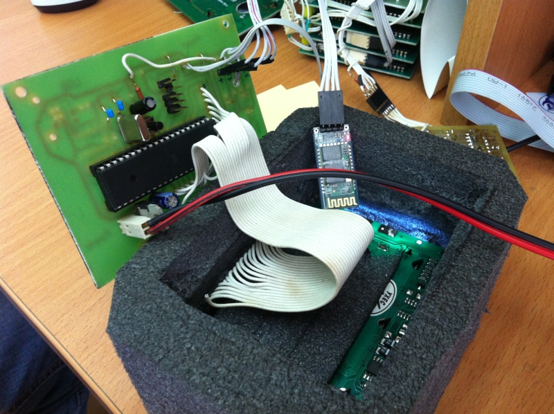
All this was embedded in the layer of insulation, which sheathed tanks, here is the gutted back side of the block that was embedded in the tank trim:
The controller program was written in C (CodeVision AVR), the client part in Delphi 7.
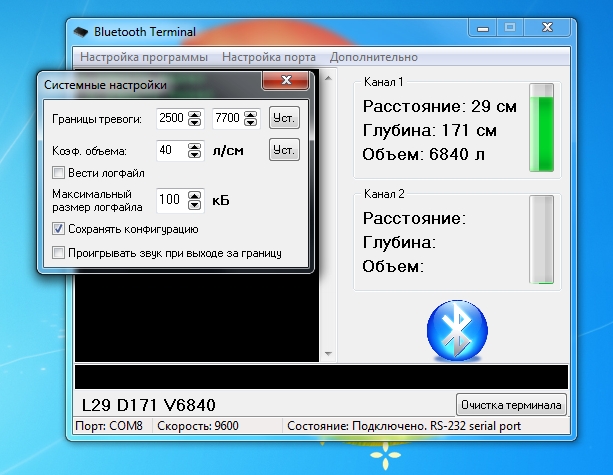
The essence of the work is as follows, the controller registers the duration of the echo pulses from the ultrasonic sensor by timer, counts into the distance, then into the volume. The data on the bluetooth is transmitted to the computer, where the graphic output of the tank filling, the distance to the surface and the depth go. All this is calculated in the controller. The maximum and minimum limits are set from the client to the controller, upon reaching which the red or green LED lights up on the lab, and the program displays a sound on the computer and the display of the tank in which it has reached the limit flashes. Also, the volume coefficient [l / cm] is set so that the sensor can be positioned or even put it on a tank with a different geometry. All parameters are stored in EPPROM. The system has two channels, data is transmitted from two tanks simultaneously. At the time of the shooting, one tank was lowered and I turned off this channel so that my eyes would not waste.
Initially, the idea was to transmit data over the wires, but it was difficult to lay 15 meters of the wire past the ceiling. By air, the distance was about 8 meters. The receiver is located in the computer, in the special cabinet near the mine, the installation control system, which is fed from the experimental tanks, is spaced apart, one is the operator's seat next to the mine and the pipeline, the second is rendered away. The sensors themselves are installed in a plastic pipe with a diameter of 100 mm inside the tank so that when they drain water into the tanks they do not splash and the level smoothly changed, there are no waves and ripples on the surface, just in case. The advantage of this is also the fact that the ultrasound sensor pattern of the ultrasound is narrow. Unfortunately, there is no photo of the installation site, the tank lids are already screwed onto 40 small bolts and the Nemer weighs;
View of the display in thermal insulation (one channel):

Globally, besides solving the level control problem in underground tanks, I have also developed a little, touched the bluetooth module, added libraries for graphics, touched the ultrasonic sensor, and progress is always good.
You can fill it all with silicone or compound, but I have not oxidized anything until at a humidity of 60-70%, the Chinese themselves write IP68 to the ultrasonic sensors themselves, who knows, maybe they really do, I still filled it with hot melt glue in a circle.
This is how the system turned out, it works properly, perhaps someone will come in handy, it is quite applicable at the cottage in the well and in other hard-to-reach places. The main thing is the idea.
I don’t regret everything that was in the archive, MK firmware, PROTEUS files, Delphi 7 raw files, compiled executables, all libraries, in short, the entire project folder. [archive password: idkfa]
AVR LevelMeter Graphic LCD 2ch BLUETOOTH.rar [2.6 Mb]
Source: https://habr.com/ru/post/156261/
All Articles