Circuit Switch FallBack: First Step on the Road to Voice in LTE

In the last article about LTE, we mentioned the technology of providing voice service CSFB (Circuit Switch FallBack). LTE networks are designed to transmit packet information; there is no voice in this network in the sense in which we understand this by the example of traditional GSM / UMTS networks. But it is possible to change this.
Currently, testing and configuration of CSFB technology, which uses the existing, traditional CS ( Circuit switching ) domain of 2G / 3G networks, is underway . This is done because the original voice over LTE technology - VoLTE (Voice over LTE), where voice is already transmitted over an IP network using LTE tools without using previous generation networks, is dependent on so many state level solutions and permissions. In order to create conditions for making calls using VoLTE, it is necessary to provide support for this functionality not only by the network, but also by the user equipment (User Equipment / UE).
Let's leave VoLTE for future articles, but for now let's consider the CSFB from the technical side.
CSFB - Circuit switch fallback
The simplified EPS network architecture for CS fallback and SMS messaging is shown in the figure and is based on the use of the SGs interface:
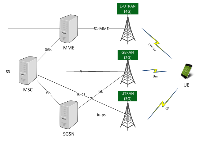
')
Features / characteristics of equipment supporting CS fallback
The UE , of course, has access to both E-UTRAN / EPC and CS domain through the GERAN and / or UTRAN network.
The MME uses the LAI and the hash value obtained from the IMSI to determine the VLR number, in case this LAI is served by several MSC / VLRs, the same hash value / function is used in the SGSN .
Everything is clear with MSC , but it is also possible to expand the functionality of CS fallback support with ICS and / or SRVCC.
Mobile Originated Call - Subscriber calls from LTE
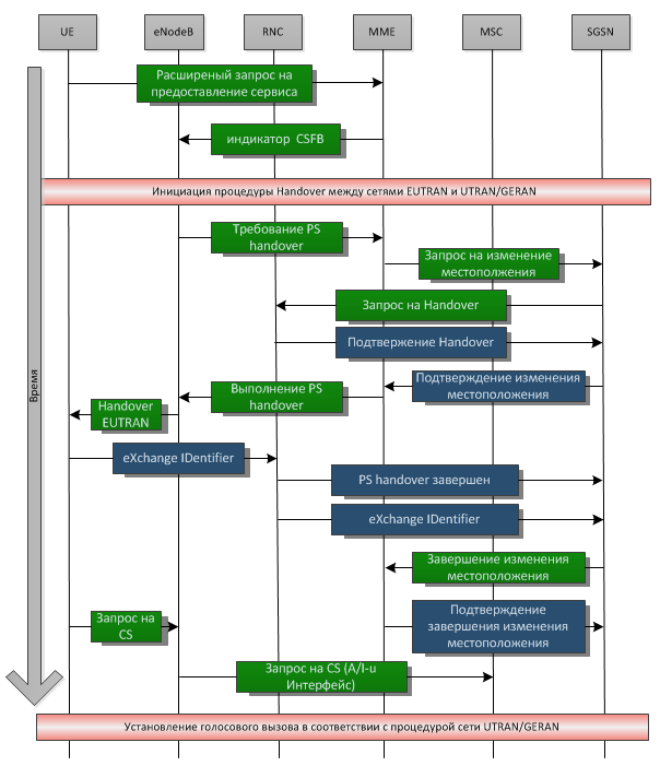
What happens during a call to a subscriber who is on the LTE network? Let's look at a simplified call flow (a diagram of the exchange of signaling messages between network elements), which will quite clearly explain everything:
Consider the basic scenario of events
The lucky owner of a phone with LTE support is walking down the street in the coverage area of 4G and 3G / 2G networks. In the background, updated mail, Facebook, Twitter and other services. Having decided to call, he performs his usual actions: dials a number andAt this moment, the first extended request is generated (2 years ago it was difficult to imagine that the simplest voice call would be interpreted as an extended request) to provide the service. The MME receives the request, having information that the subscriber is in the LTE network, informs the eNodeB about this, so that it initiates the CSFB procedure. The CSFB procedure involves transferring to a 2G / 3G network, but the phone is already actively using the network at this time: it receives mail and updates from services, and this process cannot be interrupted. Seeing the active data transfer, the eNodeB decides to make a handover to the 3G or 2G network. The decision on the choice of the network is made on the basis of measurements received from the UE. Thus, the transition between networks occurs without interruption of active data transfer sessions.
The eNodeB communicates its decision to the MME, and then the MME begins to negotiate with the SGSN. To start this process, you need to make sure that you have the necessary resources for this subscriber in the SGSN (PFCs, PDP context, APN) and in the RNC. For this, the MME transmits a location change request (Update Location) to the SGSN. SGSN, in turn, conducts the compliance of LTE services (EPS bearer service) to non-LTE services (PDP context) and requests resource allocation (PFCs - Packet Flow Context) to the RNC. Not all services will be accepted, depending on the workload of the 3G network, some EPS services may be discarded.
Then the RNC prepares the so-called “transparent container from source to receiver”, which will contain data for both the 3G network (Handover Radio Resources) and LTE (NAS container). Upon receiving confirmation of the availability of the necessary resources, the SGSN reports this to the MME, which initiates the Handover procedure (sends a “transparent container” to the eNodeB).
The eNodeB, having received the command, starts “switching” services from the MME to the SGSN, and at the same time sends the Handover command (with the “transparent container”) to the UE. At this command, the UE (smartphone) starts to rebuild to the radio part of the 3G network. For these purposes, the “transparent container” contains data for handover of both LTE and 3G networks. After rebuilding to a new network, the UE sends an XID message (eXchange IDentifier) and resumes data transfer at the same time. The RNC informs the SGSN about the successful completion of the handover, as well as relays the XID to the SGSN. After receiving confirmation of Update Location, the MME and eNodeB resources are released.
And then the standard voice call procedure worked out over the years in 2G / 3G networks.
Mobile Terminated Call - LTE call subscriber
An incoming call to LTE is almost the same as the outgoing call discussed above, except that the initiator of the call is not the UE, but the MSC.
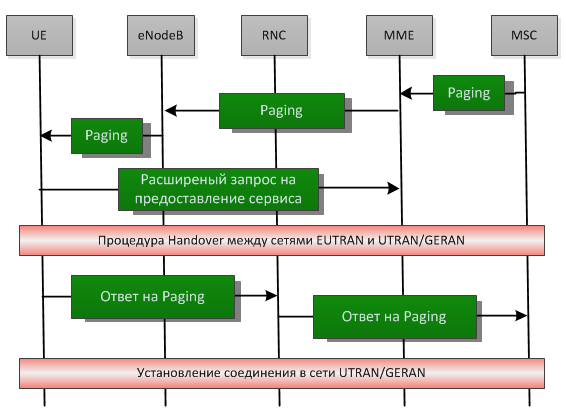
To start, on the SGs interface, the MME accepts paging from the MSC with the necessary information (IMSI, VLR TMSI, Location Information). Depending on the settings, paging is carried out either via IMSI or TMSI. In the first case, the MME uses the IMSI, in the second case it generates S TMSI from the received data and transmits to the eNodeB. After receiving the paging, the smartphone starts requesting radio resources and generates an advanced request. As in the previous scenario, a handover occurs, and after it the UE responds to paging on the 2G / 3G network. Voice connection is established.
This is how relatively easy it is to use a legacy network to replenish voice services on a new generation network on the way to the upcoming VoLTE.
Information sources
3GPP TS 23.272 - Circuit Switched (CS) fallback in Evolved Packet System (EPS); Stage 2
3GPP TS 23.401 - General Packet Radio Service (GPRS) enhancements for Universal Terrestrial Radio Access Network (E-UTRAN) access
3GPP TS 43.129 - Packet-switched handover for GERAN A / Gb mode; Stage 2
Source: https://habr.com/ru/post/156051/
All Articles