RFID tag on simple logic
 A new 7400 competition has been announced, and something new needs to be done. You can not lose face after winning last year;)
I had some vague ideas, but they were not enough to cause the reaction “Wow!” Or “You are a maniac!”. You need to work hard to stay at the level of my previous development - a capacitive scanner.
I organized a brainstorm with my comrades: Pedersen, Asbjørn and Flemming, who immediately came up with a lot of funny ideas. And Flemming mentioned RFID (he is the developer of an access control system that is based on RFID). But this is a thought. Of course, the first thoughts were about the RFID reader, but we already collected quite a lot of them, and it was boring. However, the idea was to make an RFID tag . I do not know who mentioned it first, and, as usual in brainstorming, ideas are born of the collective mind. So, it was decided to make an RFID tag collected exclusively on the 7400th logic.
Content
')
Label principle
The RFID tag sends a unique code by modulating the carrier frequency. Most tags are passive: they do not contain their own power sources and only transmit an identifier in response to a request. Regular tags use the EM4100 protocol. Many EM4100-compatible tags use the same transponder chip and exist in several configurations that differ in coding protocols and data rates. The conventional label transponder has the following characteristics:
- Carrier frequency: 125 kHz, 13.56 MHz, 433 MHz, usually with amplitude modulation
- Encoding: Manchester code, two-phase (Biphase) or phase shift keying (PSK)
- Transmission speed: 1, 2, 4 kbps or more
- Embedded non-rewritable identifier, optionally - rewritable memory
- Checksum count using parity and CRC
The EM4100 transponder operates at a frequency of 125 kHz with amplitude modulation. All types of coding are encountered, but Manchester is most often used at a speed of 2 kbps. The transponder sends 64 bits of data, which include: 32-bit identifier, 8-bit manufacturer / version code, 9-bit header, 14-bit checksum and 1 stop bit. The data in the label is encoded so that they contain a unique pattern for synchronization. The EM4100 sends a sequence of nine units that cannot be found anywhere except at the beginning of the data packet.
You can buy such tags anywhere, for example, on Itead , Seeed or Sparkfun . You can also find an RFID reader that will work with them.

The development specification easily follows from the specification of common RFID tags:
- 125 kHz carrier
- Amplitude modulation and at least Manchester coding
- 2 kbps or customizable
- Custom Data Bits
- Adding a header and stop bit
- Automatic checksum calculation
- Preferably passive power
Nutrition
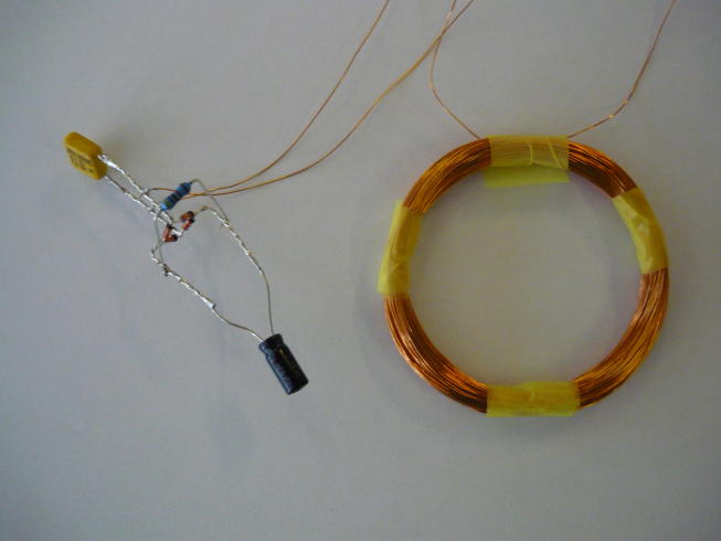
The main feature of the transponder is that it receives energy from the electromagnetic field of the reader. It would be a remarkable achievement to power the tag on the 7400's chips exclusively from the electromagnetic field. For an existing RFID reader, measurements were taken using a simple installation. We take the coil, select the parallel-connected capacitor for the resonant frequency of 125 kHz and see how much energy can be removed.
A bridge rectifier (on Schottky diodes) is connected to the resonant circuit (3.3 mH and 470 pF), followed by a 10 μF capacitor and a load: 4.7 kΩ, 12 kΩ or 47 kΩ resistors. It turns out that the transfer of maximum power occurs at a load current of about 700 μA, when the voltage reaches 19 V. In other words, more than 13 mW of power can be extracted from the electromagnetic field. At a voltage of 3.3 V, the maximum load current will be about 2 mA. That should be enough to power the many 74HCxx series chips. (Domestic analog - series KR1564. - Approx. Transl. )
74HCxx microcircuits are fully CMOS and have almost zero static current consumption. They dissipate power only when switching, recharging input and output capacitances. Taking the supply voltage equal to 3.3 V, current - 700 µA and clock frequency - 125 kHz, we find that the resonant circuit can supply the circuit with a total capacity of 1700 pF (U * C = I * T). This means that there should be enough power for a lot of chips and I / O lines.
Using the label at higher frequencies, for example, 13.56 MHz, is much more problematic. Two orders of magnitude higher frequency means two orders of magnitude greater power consumption. It follows that it is almost impossible to use this label at high frequencies.
As for the HCT series of chips (Domestic analog - series KR5564. - Approx. Transl. ) , They can not be used in this design. The HCT series has, on average, a higher quiescent current and, more importantly, additional leakage current through each input, due to compatibility with TTL levels. The input of an HCT series element will be a current source if it is not pulled to the power bus. This current is designated in the documentation as ΔIcc (additional quiescent current) at each input. Its value is 10-1000 μA, depending on the connected load. This means that a lot of energy is wasted, which is completely undesirable.
Some considerations regarding the analog part. An important factor is the quality factor of the resonant circuit. A higher Q with a constant resonant frequency means that less energy will be removed from the circuit. On the other hand, the high quality factor facilitates modulation. Modulation is nothing more than a change in parallel resistance, which entails a change in good quality: Q = R * sqrt (C / L). All variables, R, C and L, must be selected for optimal performance within the operating range. The balance should be determined experimentally.
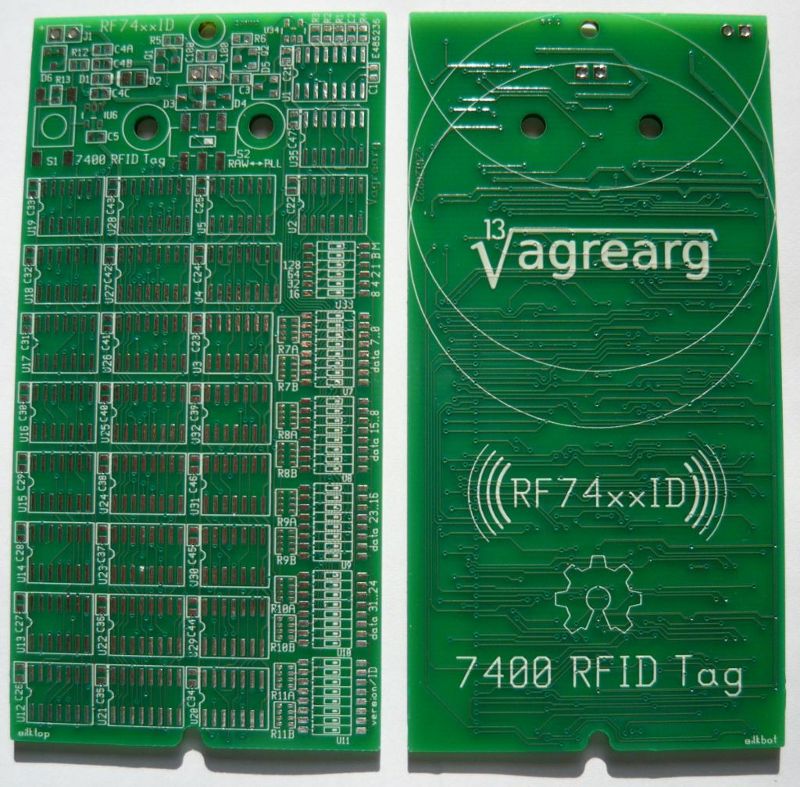
Label design
The EM4100 tag includes a data register, power circuit, clocking, modulation, and control. All components are energy efficient and provide maximum flexibility.
Schematic diagram
It should be noted that the final draft includes all bug fixes and some additions that were made at the prototype stage. Below will be detailed information about the changes. To protect the reader from the cry of "mnogabukv, niasilil!", I will immediately give the final version.
Page 1, 64-bit data register and parity scheme:

Page 2, power schemes, clocking, management, label identifier input, and timing diagrams:

The whole scheme in PDF .
Scheme in gschem format.
Data register
The EM4100 tag holds 64 bits of data, which means that the design must contain a 64-bit shift register composed of eight 8-bit 74HC165 registers. The register reloads after every 64 shifts to reset the data and start over. The data on the register entries is as follows:
- Sync pattern: nine units
- Manufacturer / Version ID: 2 blocks of 5 bits each, of which 4 bits are data and the fifth is parity
- Unique identifier: 8 blocks of 5 bits each, of which 4 bits are data, and the fifth one is parity
- Checksum: 4 parity bits, calculated by columns
- Stop bit: "0"
See the description of the protocol , there is a beautiful sign. The data is transmitted by the high bit forward. There are a total of 40 bits (8 + 32), which the user sets with the switches. Many RFID readers will ignore the “Manufacturer / Version ID” field and only give out a 32-bit unique identifier (in decimal, arrrrr!).
Line parity is counted among 4-bit groups (nibbles). The parity bit is calculated using a 4-input XOR (exclusive OR) as follows:
RPx = D0⊕D1⊕D2⊕D3 = (D0⊕D1) (D2⊕D3),
which is implemented on the three elements 74HC86. The parity for the columns is calculated similarly, but for 10 bits, using the element 74HC280 for the first nine bits and 74HC86 for the tenth.
Much of the labels have immutable identifiers. This construction can produce all possible identifiers, you only need to set the number using the switches, and the parity calculation remains the same. Despite the fact that the parity computing circuit contains many chips, it consumes almost no energy since it is in a static state. Thus, flexibility can only be achieved at the cost of adding chips, without sacrificing other features.
Resonant circuit
The heart of the power supply is the resonant circuit of the capacitor and the coil. The voltage is rectified by a bridge on Schottky diodes and is fed to a storage capacitor. Resonance in the circuit in combination with high quality will provide a sufficiently high voltage. The input voltage is limited by the chain LED + zener diode. The LED lights up when the drive is charged, and then burns excess energy, protecting the circuit from overvoltage.
The storage capacitor holds enough energy to power the tag for a while. The Zener diode limits the maximum voltage to about 12 V, and the LDO stabilizer after it requires only 0.4 volts over the operating voltage of 3.3 V. With a capacitor of 2 μF and a rated load of 800 μA, the operating time is 12V - 3.7V ) * 2µF / 800µA ≈ 20 ms. A full cycle of 64-bit transmission at 2 kbps takes 32 ms. The drive will charge at least when the modulator is turned off (about 50% of the time), so energy should be enough.
The scheme is designed so that you can connect an additional power source (3 or 4 AAA batteries), as well as turn on / off the LDO-stabilizer. The battery is optional, but I cannot guarantee that all RFID readers will deliver sufficient power.
A curious reader may ask me why the power supply provides 3.3 V, while the 74HC family can work at 2 volts. The reason for this is the PLL circuit (see below, “Clock Recovery”). VCO chip 74HC4046 can work only with a supply voltage higher than 3 V. If the PLL is not used, the supply voltage can be reduced to 2 volts. All HC chips are fast enough to cope with a clock frequency of 125 kHz even at 2 V.
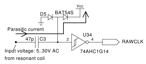
Clock recovery
The resonant circuit operates at a frequency of 125 kHz, which is used to clock the entire circuit. The signal from the coil is fed through a coupling capacitor to the Schmitt trigger 74HC14 and converted into a RAWCLK signal (in the same way, a 50 Hz signal is usually taken from a power transformer). The Schmitt trigger hysteresis is necessary because the signal has gentle fronts and can carry a lot of noise. The main problem is inductive coil interference from a 50 Hz power grid, which leads to phase noise in a clock signal. Schmitt trigger provides noise resistance and removes most of the 50 Hz interference.
An optional PLL ( PLL ), made on the 74HC4046 chip, synchronizes the clock generator with the carrier frequency of the resonant circuit. The PLL is only needed if the carrier frequency is interrupted. Such gaps can occur in RFID readers, which periodically adjust the amplitude of the electromagnetic field, so that the signal is below the trigger threshold of a Schmitt trigger. However, the reader remains able to receive data even at low field amplitudes. The PLL maintains a clock signal during such periods. The circuit has a switch to enable or disable the use of the PLL. With the PLL turned off, the power consumption is lower, but turning it on may be useful for working with some readers.
Problems with PLLs can occur with low cost readers that generate a carrier signal with significant phase noise (jitter). This causes the PLL to work continuously, adjusting the phase, which increases power consumption. Another PLL problem can arise with very bad RFID readers, which restore received data exclusively from its 125 kHz internal oscillator. If the label misses the period, the reader will be confused, and Nasty Stuck ™ will happen.
Frequency divider
Some clock signals are derived (not in the mathematical sense of the word "derivative." - Approx. Transl. ) From the main signal MCLK. The EM4100 tags are usually released at data rates of MCLK / 16, MCLK / 32 and MCLK / 64, although the value of MCLK / 64 (2 kbps) is most common. Switchable frequency divider to adjust the transmission speed is assembled on the half of the 74HC393 counter. A divider generates a DCLK signal. A set of switches sets the division factor for a clock signal.
The second half of the 74HC393 counter forms all internal clock signals (CCLK, PCLK and SCLK). The data register is shifted by the SCLK signal, which sets the data transfer rate.
The full time diagram is shown in the device diagram (page 2).
Counter modulo 128
The data register contains 64 bits, but the problem is that the data reload takes another clock. If you count only up to 64, then the end-of-count signal will override one shift signal, which means skipping a bit in the next 64-bit cycle and will lead to an incorrect start of the data transfer cycle. Simply put, a full cycle of transmitting 64 bits and reloading the register takes 65 cycles. - Approx. trans.
The 74HC40103 chip operates as a counter modulo 128, counting down from 127 to 0 at double data transfer rates, and then rebooting. The end-of-count signal (MOD128) is slightly shifted in time due to synchronization with the CCLK in order to avoid overlapping the front with the SCLK front. This is done with the help of a 74HC74 trigger, which generates a parallel loading signal for the ~ PLOAD register.
Manchester coding
The coding scheme used in most tags, as mentioned earlier, is Manchester. The main advantage of the Manchester code is in the simplicity of its generation. An exclusive OR between a clock signal and a data stream is given by the Manchester code. The 74HC86 element adds the SCLK and SDELAY signals to encode the data stream.
The actual data flow from the register, SOUT, is delayed by one cycle to form SDELAY. When the data register is reset, the SOUT is immediately changed from “0” to “1” (transition from the stop bit to the start bit). However, parallel loading of the register, as mentioned above, is not tied to the front of the shift signal, and the generation of the Manchester signal must remain synchronous with SCLK so that there are no false transitions. A delay of one clock cycle makes all bits in the data stream synchronous with SCLK.
The Manchester signal, according to forecasts, should have outliers (glitches) at transitions 0 → 1 and 1 → 0. In these places, the SCLK signal is inverted, but SDELAY and SOUT are not 100% synchronous. The outburst is triggered by the SDELAY and SCLK signals due to the 74HC74 trigger trigger delay. However, this surge is so narrow (10-30 ns) that the modulator does not have time to react to it, not to mention the receiver, in which the signal is strongly filtered. So the emission is left as is.
Two phase encoding
Another reasonably easily implemented coding scheme is two-phase. It is identical to the Manchester differential coding with phase delay and is a frequency-manipulated ( FSK ) signal superimposed on the carrier using amplitude-shift keying ( ASK ). The complexity of the two-phase coding is that the output level is always variable, while the frequency varies in accordance with the transmitted data. This difficulty can be overcome by using the double speed of the generator, and then dividing the result by two.
At the first stage, the PCLK and SCLK signals are multiplexed on the basis of the stream of transmitted data using the 74HC00 element set (AND – NO). Emissions are observed at the output of the multiplexer, for the same reasons as described above (race SDELAY and SCLK), and also because PCLK and SCLK are not synchronous. (Greetings to those who read this far and did not fall asleep. It will be more fun later. - Note. Trans .) The 74HC393 counter is asynchronous, and this causes problems. The signal with outliers cannot be passed through a divisor into two without serious consequences, because outliers can also be interpreted by the counter as impulses. The multiplexed signal is cleared of emissions by quantizing the CCLK signal, which is guaranteed to stay at a high level for much longer than the duration of the emission. Finally, dividing the frequency into two using the 74HC74 trigger completes the formation of a two-phase signal.
Switches are provided for selecting the coding type: Manchester or two-phase.
Modulator
Finally, the coded signal must be sent back to the coil in order for it to be received by the RFID reader. At both terminals of the coil, the voltage can be both positive and negative, since an alternating current is induced in it.
Amplitude modulation is performed by creating a controlled earth fault on both ends of the winding using a pair of MOS transistors, each of which operates at its own half-period of the signal. Rectifier bridge forms a closed path to the ground for each of the conclusions. Despite the fact that MOS transistors are able to respond to the above-mentioned signal surges, the resonant circuit cannot, since it is tuned to a frequency that is 2-3 orders of magnitude lower than the frequency of the emissions.
Most of the pictures and diagrams that you find on the web do not show this part or show it incorrectly. The closure is time controlled, according to coded data, and limited in resistance, due to resistors. Passive RFID tags are usually small, and operate on an order of magnitude less power than this. Labels usually have small coils, and thus, only very small modulation depths can be achieved. If the big coil in our design is short-circuited, the signal sent will most likely be so strong that it will confuse most readers. Also, short circuit of the coil requires the use of the PLL to maintain the clock frequency while the coil is closed.
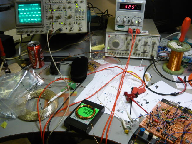
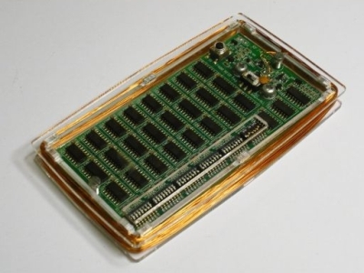
Prototype build
Now, if the theory and scheme are correct, everything should work as intended. However, practice and theory do not always correspond to each other, and my gray matter also brings me up from time to time.

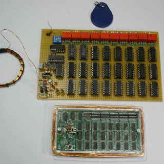
The prototype has 40 red switches for setting tag identifiers and 4 blue ones for the divider. The top row of 8 chips is the “Exclusive OR” 74HC86 elements for calculating line parity. The middle row is eight shift registers 74HC165, which form a 64-bit data register. In the bottom row, the left five microcircuits count parity by columns — four 74HC280 and one 74HC86. The rest is counters, PLL and Schmitt trigger.
The ration took about 6 hours in total. The main task of the prototype is to show the operability of the main functions and the ability of the entire device to operate from the electromagnetic field. The prototype contains only elements for Manchester coding, including the PLL circuit.

Debugging
Development of the basic scheme was an easy task. It took only a few hours. However, some things were not planned carefully enough and some functionality had to be tested experimentally.
Initial thoughts, born after searching for materials on the network, said that the modulation must be deep, very deep, and that the coil must be completely closed at the same time. It made me spend a lot of time debugging the PLL, which is not always as easy as it sounds.
PLL issues
The problem with the PLL is that you need to balance several parameters to ensure stable operation. On the one hand, it is necessary to provide a fast and stable phase acquisition, while at the same time trying to reduce both the capture range and the recovered clock drift when the carrier is interrupted. Using the documentation on the 74HC4046 was harder than I thought.There are no ready-made formulas for all components, and some need to be found on the graphs (it remains a mystery to me why the graph values diverged from reality twice, but oh well). It took some time to find suitable nominal values for all components, and to make sure that the frequency of 125 kHz fell in the middle of the VCO range, and at the same time the drift was insignificantly small.
During the drift analysis, I also found a significant portion of the 50 Hz interference, which gives frequency modulation to the PLL signal. Strong compression of the coil in the hand cleared the tips. The problem was that the phase comparator at the input of the PLL has a variable response threshold, due to the fact that the input signal is not binary. A clock recovery device with capacitive coupling yielded fronts unsuitable for logic circuits. It was found that the Schmitt trigger solves this problem.
An important feature of the Schmitt trigger is that it consumes more power during signal fronts. The reason for this is that the input stage operates in linear mode in conjunction with feedback to ensure hysteresis. Fortunately, the time spent in high power mode is small and the total power consumption is limited. But still the use of a Schmitt trigger leads to a leak in the system.
Cheap readers and junk alarms
When I started the project, I had no idea how sensitive the RFID reader would be to the modulated signal. Therefore, the modulation was implemented in the form of a complete coil circuit, as was found on the network. It soon turned out that the modulation was too deep, and the RFID reader could not extract the start and stop bits from the signal. The reader’s electronics were simply overwhelmed by this modulation and showed all kinds of garbage.
The only available reader had to open and solder a few wires to its board in order to see what data it actually takes. It turns out that an RFID reader can receive data from a coil shorted by a current source of the order of 50-100 μA. This is somewhat far from the 2.5 mA, which gives the complete closure of the coil. An additional advantage is that the PLL is now optional. Clock recovery will continue even when the modulator closes the coil. Residual induction of the coil was enough to keep clocking.

The modulator was originally assembled on bipolar transistors. This led to shallow signal fronts, because the transistors worked in low-power mode, which means very slowly. Replacing them with MOS transistors made the modulator faster and saved the next 27 µA of current consumption. I only had transistors in SOT-23 packages (Small cockroaches for SMD mounting. - Approx. Transl. ) , And I had to put them on a printed circuit board with the help of pins. The 3.3-volt LDO-stabilizer, which was at hand, was in the SO-8 package, it was mounted with wires on a piece of the male connector.
The only RFID reader was of unknown production and of adequate quality. He met the worst expectations. If you send incorrect data to the reader, you can: a) hang the reader, b) get garbage in the computer and c) curse everything, trying to understand why something is not working as expected. The only thing that turned out, is that you had to assemble your own reader in the first place. It turned out that the readers at the entrance doors of the building were much more reliable and were able to digest everything that I passed on to them.
Search for logical errors
After receiving a normally decoded signal on the reader, it still did not work as it should. The scheme showed two errors.
The first was in the counter modulo 128, which was clocked on the leading edge of the PCLK signal. However, I had to - in the back. The prototype sent 10 start bits instead of nine because the PLOAD signal overlapped the leading edge of the shift clock signal. A simple PCLK inverter solved this problem. The final design, with a two-phase encoder, forms the correct PCLK signal as part of the encoder operation.
The second error was the polarity of the Manchester code. The only mention in the network was: “low level means high current” and contained a “low → high level” transition diagram for a logical “1”. The description allows many interpretations. It turns out that this means: “low level means the modulator is on (short-circuited coil)”. Fortunately, the delay in the data flow to form SDELAY gave both direct and inverted data streams. The conversion of the Manchester encoder to use the inverted signal was trivial.
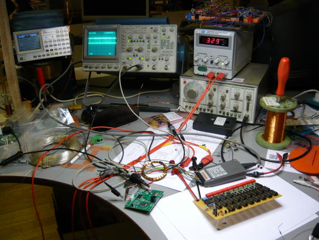
Passive power test
The power consumption of the entire prototype was measured to see if passive power was possible. Current consumption at 3.3 V ranged around 780 μA, it is small enough to close the circuit and transfer the prototype to passive power.
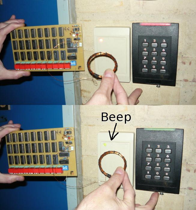
And then ... nothing happened to the cheap reader.
Everything worked as expected, food arrived, the data was sent, and suddenly, suddenly, “BIP!”. The code was correctly recognized and displayed on the computer screen to which the reader is connected. Success! Now you can open the door with a homemade RFID tag.
In pursuit of resonant power
Power from the resonant circuit must be configured so that the reader does not get lost too often, and at the same time, enough energy is extracted to operate the tag. It turned out to be harder than I thought. As mentioned earlier, good quality plays a significant role. In fact, you need a small coil, large enough for energy, but small enough not to load the transmitter too much and provide easy modulation.
Note that the resonant LC circuit does not work exactly at the resonant frequency calculated for the selected components. The reason is that the label circuit creates a (slightly capacitive) load for the circuit. Thus, the coil should be slightly smaller than calculated. This has the advantage that you can make a coil in accordance with theory, and then remove the coils before reaching the correct frequency.
It turned out that the cheap reader was very sensitive to high loads, and the lower the load was, the better it worked. The original coil, 3.3 mH, was halved several times, until a certain stable compromise was found with an inductance of about 680 mH. The second change was a decrease in the capacitance of the storage capacitor from 10 to 2 microfarads. The reader still fails every now and then, but at least it works more often than before.
In any case, the controller on the door seemed to be pleased with everything I sent, and did not let me down even once (even if I forgot my real key during testing).
An unnamed RFID reader works great when the tag has external power. When using an external source, it seems better to turn on the PLL. I think they saved too much on decoupling capacitors;)
After discussing with Mark (the guy who uses this fig reader), he told me that he had problems with this reader, even using normal tags. We decided to give him a small debugging session. The reader’s power supply circuits contained 200 mV pulsations (at 125 kHz) and some unpleasant pulses here and there. Soldering additional 1 μF capacitors + 100 nF to the places on the board, marked with silk-screen printing, but not used, significantly improved the reader's performance. Now it stumbles even less often and can read data from the prototype even with passive power.
Note to all: do not buy such govnoshchityvateli. Or buy a good one, or collect it yourself.
If you think that the story ends here, then you are mistaken. There is still room for improvement of the modulator, and significant changes have allowed it to work much better. Even a cheap untitled reader can be made to work well.
Printed circuit board
Looking at the original design and considering the options, it was decided that this gadget is too cool to leave it alone as a prototype. He just begs for a little more attention and bring the development to an absurd end. A printed circuit board was developed, and, with some caution, all the details fit in an area of 50x100 mm in two layers, without giving out errors of the “Not enough space” tracer. Size 50x100 means availability of mass production on ITead or Seeed (Custom Printed Circuit Board Manufacturing Services. - Approx. Trans. ) . However, making credit card-sized fees has proven too difficult.

SMD-, . 412 0,3 / 7 mil. , , , , , : 1, 2, 4 8 /.
, .
- 128 74HC163, 74HC40103
- - (2x24 ). +,
- 74HC14, . , , 74HC1G14,
- LDO- - ( «»)
- / . ,
C
The cost of parts is less than $ 30 excluding fees and coils. You will have to make a coil yourself (see below). In fact, the DIP switches and circuit board are the most expensive components.
You can replace most of the components with those that you have. However, the input capacitors must be able to withstand at least 16 V. In addition, you must use 1% resistors and 5% capacitors for the resonator and the PLL, so that the parameters match the calculated ones.
It should be noted that decoupling capacitors are all 10 nF (instead of the usual 100 nF). This is to reduce the load on the resonant circuit. The circuit operates at a low frequency and can withstand a slightly increased noise level on the power bus, since the supply voltage is higher than the minimum allowed.
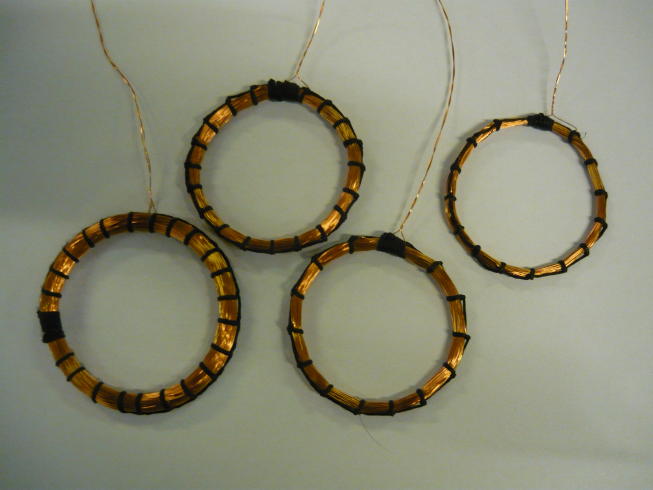
According to calculations, the coil should contain 89 turns of wire with a diameter of 0.4 mm and have an average diameter (measured at the center line of the winding) 50 mm. The coil was wound on a mandrel with a diameter of 48 mm (cartridge of silicone sealant), and then with the help of a waxed cord, it was given a beautiful toroidal shape and tightly laid the coils. The desired resonance frequency is probably achieved with 88 or 87 turns, depending on the tolerances.
You can make a coil of any shape that you like (for example, square or rectangular), if you correctly adjust the circuit to resonance. However, changing the shape will require some experimentation, since the inductance and the strength of the electromagnetic coupling depend on the size (see below for a rectangular coil).
If you measure the inductance of a coil, do it at a frequency of 125 kHz. The inductance depends on the frequency due to the parasitic capacitance of the coils and the electromagnetic coupling between them (for example, a 3.3 mH coil shows an inductance of less than 100 μH at a frequency of 1 kHz). Parasitic parameters will also affect the resonant frequency and the quality factor achieved.
Safety notes
As you can see, emulation of RFID tags is trivial. All systems where only a key is required for access are vulnerable to tag emulation attacks. RFID in access control systems should only be used as one of the authentication factors, in conjunction with “what you have + what you know” (although this may be ineffective ).
Even encrypted tags are vulnerable to multiple attacks. In addition, it is becoming easier to emulate tags on NFC- enabled smartphones (which usually operate at 13.56 MHz). Just write the field modulation application correctly, and you can do whatever you want.
As a standard excuse, I remind you that the author (And the translator! - Approx. Transl. )assumes no responsibility for the consequences of using the information from this article. The reader must be responsible for all his actions.
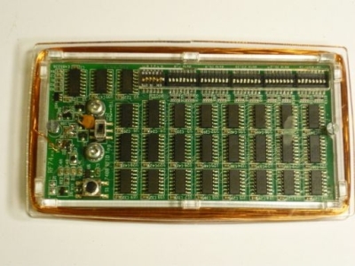
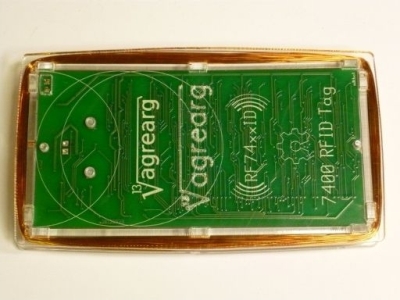
Housing
Sometimes very lucky. A beautiful case would not hurt right now, when the prototype is finished, and the printed circuit board is ordered. And it was at this time that Fleming finished collecting and running the OSAA PhotonSaw laser cutting machine . After a year of work on the project, the laser is ready to cut out its first details. Flemming and Rune do the last adjustments and put in place the aluminum cover of the laser cabinet. You can imagine how we all were glad to see that this thing works.
With a working machine, we got the opportunity to test our project in real life. The housing for our RFID tag was made from 2mm glass. This case is the first object made at PhotonSaw, yes!
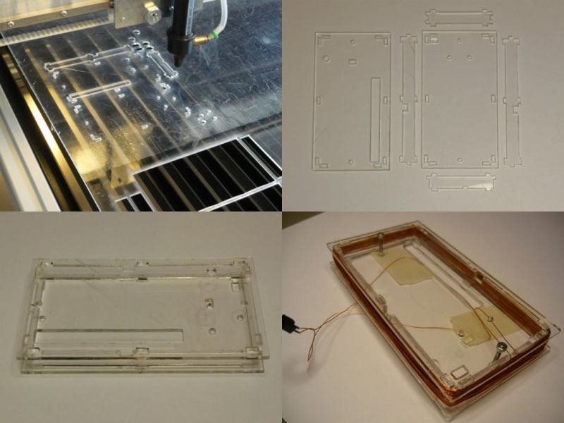
The idea was born to place the coil on the outside of the case. At first it was decided to use half the height of the body, but this did not work in practice (additional holes in the long sides, thus, are not used). The coil was simply superb around the perimeter of the whole case, although I had doubts whether the rectangular winding (105x55 mm) would be too large for a normal electromagnetic coupling.
The test coil was wound, without any calculations, with a 0.4 mm wire in 66 turns. And, obviously, we were lucky again, because the coil turned out exactly as it should, inductance 645 μH, with the connected label giving the resonant frequency of 125.2 kHz. The test on the door reader showed that the prototype works just fine with this coil.
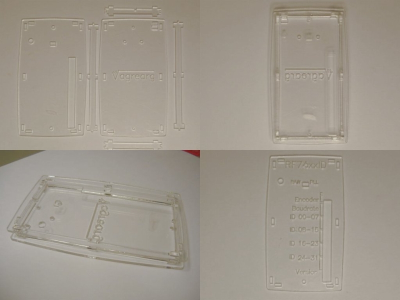
With a coil outside the case, the thickness of the latter can be reduced. The internal thickness now depends only on the height of the parts on the board, and taking into account the thickness of the board it should be about 6 mm. In addition, it would be nice to add engraving. Flemming suggested rounding the sides of the hull for aesthetic and ergonomic reasons. A curved body will also better protect the sides of the coil, because where there is no strong tension, the turns of the wire like to crawl out.
PhotonSaw : . . , . , .
:
. , , .

, , . , :
- Dip switch pads are too close together. I had to lightly grind the switch bodies from the sides so that they fell into place. In the next version, the gaps increased by 10 mil.
- Screenprinting with the designation of transmission speeds is done incorrectly. Values should go in the order of "1 2 4 8", and not "8 4 2 1". Fix it in the next version.
- The changes made to the prototype seem to work too well in terms of energy, which led to a number of unexpected problems. It was discovered parasitic power circuit in the off state.
- Modulation works hard and unstable. The main reason is the different levels of input voltage combined with a modulator that operates in voltage modulation mode.
Parasitic power
New switchable stabilizer (MCP1804) saves a lot of energy. Its meaning is that the connected battery will last long if the label is in a state of ultra low consumption. But when the coil is located near the reader, there is a detour to power through the clock recovery circuit.
Through the separation capacitance (47 pF, there is a resistance of approximately 27 kΩ at a frequency of 125 kHz) and protective diodes, the current is fed to the power lines. The energy coming from the coil is enough to maintain the supply voltage of about 1 V. The current can reach 250-500 μA. Surprisingly, 74HC microcircuits seem to work with this power. Unfortunately, at such a stress, rather strange things happen. The 74HC chips have an internal reset circuit, and you need to make sure that it works. Please note that disabling the protective diodes does not help. At the inputs of microcircuits there are internal protective diodes, which in this case open and do the same work.
A power reset is triggered only if the supply voltage drops below a certain level for a period of time. If the voltage remains too high, then the internal logic can get confused, because some of its parts may be in an unspecified state, while others work properly. Internal reset is required to set all chips in a consistent state. Thus, the circuit will operate unstable at very low supply voltages.
Symptoms were observed as follows: the label works for some time, while sending the correct data. If you remove the coil from the reader, and then return it back, you can bet on whether the label turns off. Sometimes it works, sometimes it doesn't. Turning off the PLL makes the situation worse. Low power consumption leads the reader to receive data from a disabled tag from time to time. This is what “energy efficient system” means.
There are two solutions: 1) reduce the capacitor in the clock recovery circuit to 15 pF, and 2) connect a 22–100 kΩ resistor between the power supply and ground to reset the excess energy. The second method leads to an increase in leaks during operation and is not really required when the capacitance of the capacitor decreases. However, it is provided as an option, and it is still better than the indeterminate state of the chips.
Current or voltage modulation
The modulator brought a fresh batch of headache. The modulation completely disappeared when the coil was placed at a certain distance from the reader. It could also happen when moving the coil to or from the reader.
The reason was in the modulator circuit. MOS transistors close the coil to a resistor of a certain resistance. However, if the energy consumption from the circuit is large, the resistance of the modulator is much higher than the resistance of the power supply. This leads to the fact that the modulation depth depends on the current consumption, and this is not very good. The situation was worsened by the choice of the limiting Zener diode to a lower voltage than in the prototype.
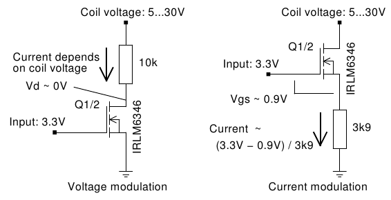
It was decided to switch the modulator from the voltage modulation mode to the current modulation mode. For the first mode, the resistor was in the drain circuit, and now it is connected between the source and ground. On this resistor, the gate-source voltage will drop until the value remains just above the opening threshold of the transistor (0.9-1.1 V), which will translate the transistor into a linear mode. Now the current through the transistor will be stable, regardless of the voltage on the drain.
Testing on the prototype showed that current modulation works very well. A cheap nameless reader no longer fails (well, maybe once a hundred or so). It can be assumed that this change will work wonderfully on other readers, and the label will now probably be able to work on most of them.
Finished version 1
You may notice the changes made on the PCB. I did not have a 15 pF SMD capacitor, I had to solder the usual one with legs. The modulator was overgrown with additional resistors at the source of the transistors. Generally acceptable for the first version.
(pictures are clickable)

Video demonstration
Conclusion
You might think that this project, compiled on the 7400 logic, can be attributed to retro-circuitry, but this is not quite so. Firstly, the modern 74HC family is not that old either. Secondly, low-power schemes are always relevant. Third, single logic chip chips (such as the Schmitt trigger used) are often used in modern designs. It is often forgotten that the development of technology does not stop for old families of microcircuits. They just became less noticeable on the background of the overall diversity.
The analog part was more difficult to develop than the digital one. Partly due to the lack of specifications, but mainly due to the many trade-offs required to meet the parameters, and unforeseen side effects. Digital designs have relatively few options, while analogs usually require a balance between different (and often opposite) criteria.
I have to admit that the 74HC chips are very, very well made. The developers knew what they were doing and achieved very low power consumption. At first I had some doubts whether the label could work from passive power, but after reading the specifications, it remained only a question of the correct circuit design. Although, there are still opportunities to optimize different parts of the label.
Now let's see how this project will show itself at the competition 7400 2012. Submission of applications for the competition ends on November 31. We wish the author good luck! - Approx. trans.
Source: https://habr.com/ru/post/155973/
All Articles