Network infrastructure of RTLS systems
Before continuing the discussion of the main features of ZigBee networks, I want to insert a small remark.
What I wrote about in the previous topic and I am going to continue in this one refers to the ZigBee Pro Feature Set 2006 standard approved in 2007. This specification already contains all the main features that make ZigBee networks the most preferable option when creating sensor networks for various purposes, exactly:
1) self-organization and self-healing,
2) structural flexibility - the ability to create networks of different topology - star, tree, cellular (mesh) network,
3) the ability to select routing algorithms, depending on the requirements of the application,
4) the application standardization mechanism — application profiles, clusters, endpoints, bindings,
5) flexible security mechanism
6) low power consumption
7) ease of deployment, maintenance and upgrades.
But this does not mean that life has stopped.
Back in 2008, in order to ensure the functioning of the home network (Home Area Network - HAN) based on the IP alliance ZigBee began work on expanding its standard - the Smart Energy 2.0 profile. The profile assumes the support of any transport level based on IP-compatible standards, including ZigBee IP and other transmission technologies - both radio frequency and power wiring - Power Line Carier (PLC).
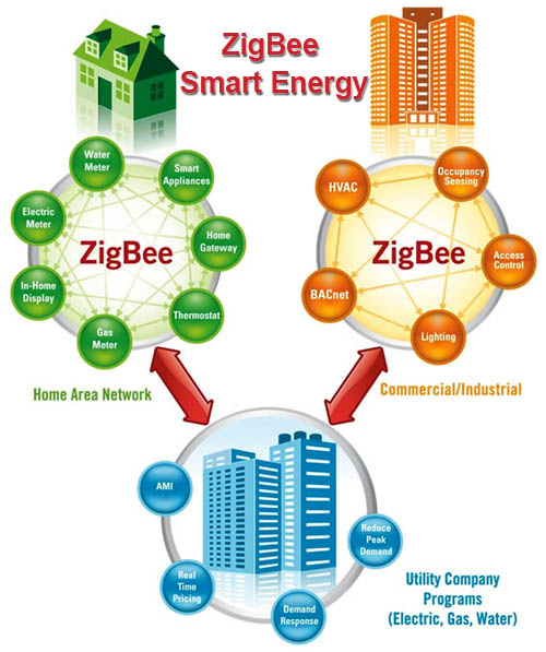
The profile provides interaction between ZigBee and other network technologies. The ZigBee Alliance is developing an Internet Protocol (IP) network layer called ZigBee IP based on 6LoWPAN technology (IPv6 over low-energy wireless personal networks). A public discussion of the latest working version (draft 0.9) of the Smart Energy 2.0 profile ended on August 25, 2012. The release of the final version is expected soon.
But now many network devices supporting ZigBee IP are being released, for example:
')
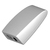
ZigBee Gateway - Ethernet
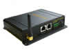
ZigBee Gateway - WiFi - Ethernet

ZigBee - USB Adapter /
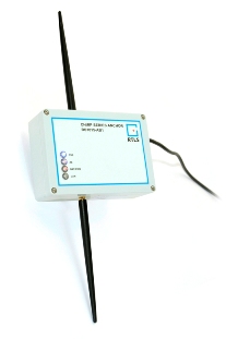
ZigBee Gateway - Ethernet + CSS Interface RTLS
The relatively large dimensions of the device are explained by the fact that it is made in a dusty and waterproof housing and has a built-in uninterruptible power supply for 8 hours of operation. The Ethernet interface can be electrical or optical — optionally. Learn more here: www.rtlsnet.ru/products/product/4 .
By the way, Smart Energy is by no means the only extension of this rapidly developing standard. You can find many more interesting topics related to ZigBee networks, but for now “let's go back to our sheep”. Let's continue the discussion of the basic features of ZigBee from the place where we stopped - from the stack of protocols. Figure repeat:
ZigBee protocol stack
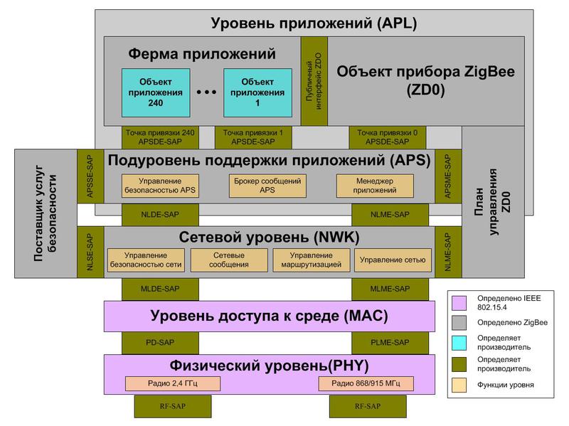
The ZigBee protocol stack provides four layers: APL — application layer, NWK — network layer, MAC — medium access level, and PHY — physical layer. As usual, upstream protocols use downstream services.
The application layer and the network layer are governed by the ZigBee specification, the lower layers, the MAC and PHY are governed by IEEE 802.15.4.
The APL application tier includes the Application Framework (Application Framework), the ZigBee Device Object (ZDO), and the Application Support Layer (APS).
The application farm describes how to create profiles and defines standard data types, descriptors, frame formats, and key pair values, and also includes application objects (there can be up to 240 of them in the device).
Application objects are software modules that control ZigBee devices at the endpoints. We'll talk more about this when we look at application profiles, endpoints, clusters, and bindings.
The ZigBee Device Object (ZDO) determines what role a device plays in the ZigBee network: coordinator, router, or end device. Zdo
initiates and accepts connection requests, and establishes secure communication between devices.
The ZDO Management Plan (ZDO Management Plane) supports ZDO communication with the APS and NWK sublayers, allows the ZDO to handle application requests for network access and ensures security.
Sub-level application support (Application Support Sublayer - APS). Responsible for providing data to applications, managing network attachments, and storing attachment data in a table.
The Security Service Provider (SSP) is configured by the device object and provides security mechanisms for encryption levels — NWK and APS.
The network layer (Network Layer - NWK) handles network addresses and routing over MAC layer calls. In addition, the NWK starts the network if the device is a coordinator; assigns network addresses; adds and removes network devices; routes messages; applies security policy; searches for routes.
The Medium Access Control Layer (MAC) layer provides reliable communication with neighbors, helps resolve conflicts and increase efficiency. The level is responsible for assembling and decomposing data packets.
The Physical Layer (PHY) provides a radio interface. The physical layer includes two layers operating in different frequency ranges. One level covers the 868 MHz bands for Europe and 915 MHz for the USA and Australia. The second operates at 2.4 GHz and is used almost worldwide.
Access points
The connection between the elements of the ZigBee protocol stack is carried out through service access points (SAP), as shown in the figure.
A stack profile defines network parameters — its type (topology), dimensions, supported routing algorithms, application services, routing table sizes and application bindings, security parameters, etc. The stack profile of a specific ZigBee network is programmed by the network designer (administrator), based on the specific application.
For example, the network topology is determined by three parameters: the maximum network depth (nwkMaxDepth), the maximum number of router child connections (nwkMaxChildren), and the maximum number of connections to child routers (nwkMaxRouters). The exact structure of the ZigBee network depends on the location of the devices and the passage of radio waves at the time of formation of the network and therefore cannot be unambiguously predetermined. But the mentioned parameters of the stack profile impose certain restrictions on the network structure.
For example, if in a particular application, devices must physically be placed in a line (along a conveyor or transmission line poles), it suffices to assign the values nwkMaxChildren = 1 and nwkMaxRouters = 1 to the parameters in order to obtain a linear structure. The values of nwkMaxDepth> 1, and nwkMaxRouters> 0 give a tree structure, and nwkMaxDepth = 1 and nwkMaxRouters = 0 - the star.
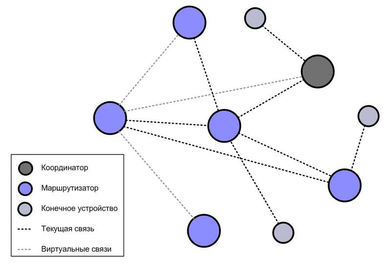
In a mesh (mesh) network, each router is connected with at least two others and can broadcast messages of immediate neighbors along a given route. Figure 3 shows an example of a mesh network consisting of a coordinator, five routers, and three end devices.
In a mesh network, each of the devices can communicate with any other device, either directly or through intermediate devices, that is, using a “multi-hop” connection.
The multi-step transmission capability helps maintain network survivability (self-healing). If a device fails, becomes unavailable due to interference, or simply reboots, packets are routed through the remaining devices.
ZigBee mesh
ZigBee networks use several routing algorithms. The choice of allowed algorithms is programmed in the stack profile, depending on the purpose of the network. The choice of a specific algorithm from among the allowed ones occurs automatically, depending on the state of the network and current conditions.
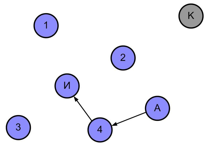
The “Ad hoc On Demand Distance Vector” (AODV) algorithm is fundamental in ZigBee networks. The search for the route from the “source” (I) to the “addressee” (A) in this case occurs as follows (illustrated by drawings):
Step 1 - the source sends a broadcast "route request to A".
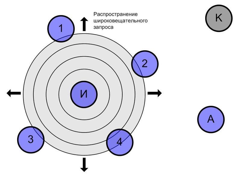
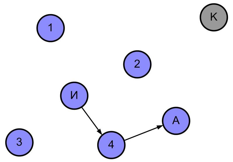
Step 2 - each device that received a route request, makes an entry in its routing table and transmits the request, including its entry in the payload. The entry indicates the “logical distance” from the sender of the request to its recipient. "Logical distance" (LR) takes into account the quality of communication between the sender and the recipient of the request. The following devices, having received the relayed request, add their entry to the packet and transmit it further. "Logical distance" increases with each step. This continues until the request reaches the addressee A. In the mesh network, the request reaches the addressee in many ways. Obviously, the “logical distances” recorded in the queries are different.
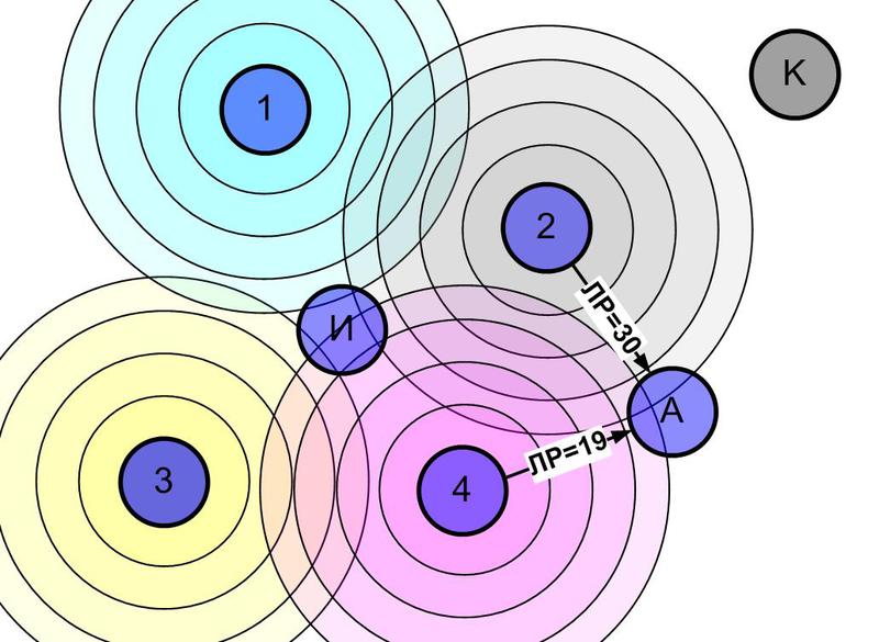
Step 3 - addressee A sends the answer to the device from which the packet came with the minimum “logical distance”. This device arrives with the package in the same way, and so on, until the answer reaches source I. The answer will be returned along the optimal (with the minimum "logical distance") path previously passed by the request.
Step 4 - the answer, returning along the optimal path, forms a table of the direct route for transferring packets from source I to destination A.
The described algorithm is universal and allows you to choose the best routes. However, its implementation requires a significant amount of device memory for storing route tables. In addition, significant network traffic is required to search for routes in extensive networks.
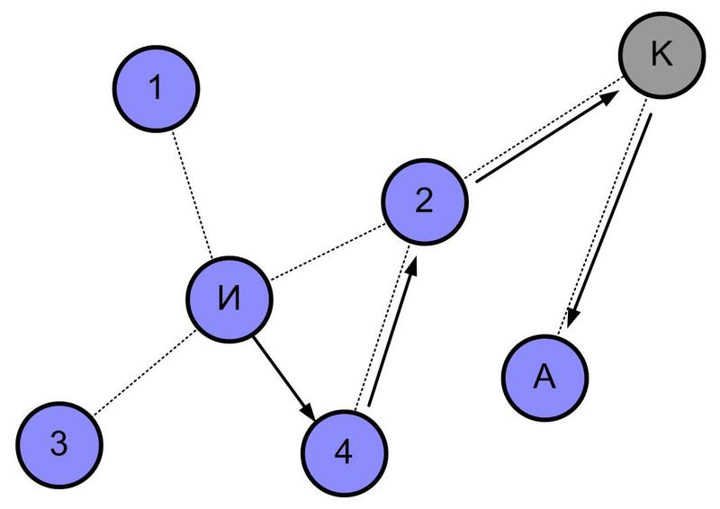
Therefore, an alternative algorithm is implemented in ZigBee networks that saves memory. The algorithm is based on the fact that the network addresses in ZigBee are hierarchically distributed. Devices that are not endowed with the AODV algorithm, and devices that have exhausted routing capabilities, can use hierarchical routing — less efficient, but quite practical.
Hierarchical routing
When forming a ZigBee network, the coordinator and then the attached routers assign address ranges to child devices in a hierarchical order. As a result, each device can determine whether the recipient address of the packet being sent belongs to any of its “child” branches or is located in another part of the network. Accordingly, the device can transmit a packet to the child device, the address range of which includes the recipient's address, or "up".
For the example in the figure below, the packet is sent by the source AND to the addressee A. However, unlike the above case, device 4 does not have enough memory for the routing table. Not knowing the optimal route to destination A, device 4 uses hierarchical routing and sends the packet upwards to device 2. Next, the packet is sent to coordinator K, who sends it to destination A.
Hierarchical routing is simple and does not require memory for the routing table. This allows low-cost devices that do not store routing tables to participate in the ZigBee network. The disadvantage of this algorithm is in extending the package path even if there is a direct connection between the source and the addressee.
Hierarchical routing
Routing to the aggregator (Many to one)
In many applications of wireless networks, there is a device - an aggregator that collects data from other network devices. To save traffic, the ZigBee PRO specification provides for a special broadcast route request. Directed by the aggregator, such a query allows you to create in the routing tables of all routers in the network records with the aggregator as the recipient.
Explicit Routing
With explicit routing, the entire packet path is indicated by the sender directly in the packet. To save the route in the package can be specified in part.
Explicit routing allows you to forward packets through a number of low-cost devices that do not store routing tables, but reduces the payload, so the route for explicit routing is limited to five nodes.
I’ll stop on this for now. In the next topic I’ll talk about application profiles, clusters, endpoints, bindings, and a little about security mechanisms.
What I wrote about in the previous topic and I am going to continue in this one refers to the ZigBee Pro Feature Set 2006 standard approved in 2007. This specification already contains all the main features that make ZigBee networks the most preferable option when creating sensor networks for various purposes, exactly:
1) self-organization and self-healing,
2) structural flexibility - the ability to create networks of different topology - star, tree, cellular (mesh) network,
3) the ability to select routing algorithms, depending on the requirements of the application,
4) the application standardization mechanism — application profiles, clusters, endpoints, bindings,
5) flexible security mechanism
6) low power consumption
7) ease of deployment, maintenance and upgrades.
But this does not mean that life has stopped.
Back in 2008, in order to ensure the functioning of the home network (Home Area Network - HAN) based on the IP alliance ZigBee began work on expanding its standard - the Smart Energy 2.0 profile. The profile assumes the support of any transport level based on IP-compatible standards, including ZigBee IP and other transmission technologies - both radio frequency and power wiring - Power Line Carier (PLC).
The profile provides interaction between ZigBee and other network technologies. The ZigBee Alliance is developing an Internet Protocol (IP) network layer called ZigBee IP based on 6LoWPAN technology (IPv6 over low-energy wireless personal networks). A public discussion of the latest working version (draft 0.9) of the Smart Energy 2.0 profile ended on August 25, 2012. The release of the final version is expected soon.
But now many network devices supporting ZigBee IP are being released, for example:
')
ZigBee Gateway - Ethernet
ZigBee Gateway - WiFi - Ethernet
ZigBee - USB Adapter /
ZigBee Gateway - Ethernet + CSS Interface RTLS
The relatively large dimensions of the device are explained by the fact that it is made in a dusty and waterproof housing and has a built-in uninterruptible power supply for 8 hours of operation. The Ethernet interface can be electrical or optical — optionally. Learn more here: www.rtlsnet.ru/products/product/4 .
By the way, Smart Energy is by no means the only extension of this rapidly developing standard. You can find many more interesting topics related to ZigBee networks, but for now “let's go back to our sheep”. Let's continue the discussion of the basic features of ZigBee from the place where we stopped - from the stack of protocols. Figure repeat:
ZigBee protocol stack
ZigBee protocol stack
The ZigBee protocol stack provides four layers: APL — application layer, NWK — network layer, MAC — medium access level, and PHY — physical layer. As usual, upstream protocols use downstream services.
The application layer and the network layer are governed by the ZigBee specification, the lower layers, the MAC and PHY are governed by IEEE 802.15.4.
The APL application tier includes the Application Framework (Application Framework), the ZigBee Device Object (ZDO), and the Application Support Layer (APS).
The application farm describes how to create profiles and defines standard data types, descriptors, frame formats, and key pair values, and also includes application objects (there can be up to 240 of them in the device).
Application objects are software modules that control ZigBee devices at the endpoints. We'll talk more about this when we look at application profiles, endpoints, clusters, and bindings.
The ZigBee Device Object (ZDO) determines what role a device plays in the ZigBee network: coordinator, router, or end device. Zdo
initiates and accepts connection requests, and establishes secure communication between devices.
The ZDO Management Plan (ZDO Management Plane) supports ZDO communication with the APS and NWK sublayers, allows the ZDO to handle application requests for network access and ensures security.
Sub-level application support (Application Support Sublayer - APS). Responsible for providing data to applications, managing network attachments, and storing attachment data in a table.
The Security Service Provider (SSP) is configured by the device object and provides security mechanisms for encryption levels — NWK and APS.
The network layer (Network Layer - NWK) handles network addresses and routing over MAC layer calls. In addition, the NWK starts the network if the device is a coordinator; assigns network addresses; adds and removes network devices; routes messages; applies security policy; searches for routes.
The Medium Access Control Layer (MAC) layer provides reliable communication with neighbors, helps resolve conflicts and increase efficiency. The level is responsible for assembling and decomposing data packets.
The Physical Layer (PHY) provides a radio interface. The physical layer includes two layers operating in different frequency ranges. One level covers the 868 MHz bands for Europe and 915 MHz for the USA and Australia. The second operates at 2.4 GHz and is used almost worldwide.
Access points
The connection between the elements of the ZigBee protocol stack is carried out through service access points (SAP), as shown in the figure.
Stack profile
A stack profile defines network parameters — its type (topology), dimensions, supported routing algorithms, application services, routing table sizes and application bindings, security parameters, etc. The stack profile of a specific ZigBee network is programmed by the network designer (administrator), based on the specific application.
For example, the network topology is determined by three parameters: the maximum network depth (nwkMaxDepth), the maximum number of router child connections (nwkMaxChildren), and the maximum number of connections to child routers (nwkMaxRouters). The exact structure of the ZigBee network depends on the location of the devices and the passage of radio waves at the time of formation of the network and therefore cannot be unambiguously predetermined. But the mentioned parameters of the stack profile impose certain restrictions on the network structure.
For example, if in a particular application, devices must physically be placed in a line (along a conveyor or transmission line poles), it suffices to assign the values nwkMaxChildren = 1 and nwkMaxRouters = 1 to the parameters in order to obtain a linear structure. The values of nwkMaxDepth> 1, and nwkMaxRouters> 0 give a tree structure, and nwkMaxDepth = 1 and nwkMaxRouters = 0 - the star.
Mesh network
In a mesh (mesh) network, each router is connected with at least two others and can broadcast messages of immediate neighbors along a given route. Figure 3 shows an example of a mesh network consisting of a coordinator, five routers, and three end devices.
In a mesh network, each of the devices can communicate with any other device, either directly or through intermediate devices, that is, using a “multi-hop” connection.
The multi-step transmission capability helps maintain network survivability (self-healing). If a device fails, becomes unavailable due to interference, or simply reboots, packets are routed through the remaining devices.
ZigBee mesh
ZigBee Routing
ZigBee networks use several routing algorithms. The choice of allowed algorithms is programmed in the stack profile, depending on the purpose of the network. The choice of a specific algorithm from among the allowed ones occurs automatically, depending on the state of the network and current conditions.
The “Ad hoc On Demand Distance Vector” (AODV) algorithm is fundamental in ZigBee networks. The search for the route from the “source” (I) to the “addressee” (A) in this case occurs as follows (illustrated by drawings):
Step 1 - the source sends a broadcast "route request to A".
Step 2 - each device that received a route request, makes an entry in its routing table and transmits the request, including its entry in the payload. The entry indicates the “logical distance” from the sender of the request to its recipient. "Logical distance" (LR) takes into account the quality of communication between the sender and the recipient of the request. The following devices, having received the relayed request, add their entry to the packet and transmit it further. "Logical distance" increases with each step. This continues until the request reaches the addressee A. In the mesh network, the request reaches the addressee in many ways. Obviously, the “logical distances” recorded in the queries are different.
Step 3 - addressee A sends the answer to the device from which the packet came with the minimum “logical distance”. This device arrives with the package in the same way, and so on, until the answer reaches source I. The answer will be returned along the optimal (with the minimum "logical distance") path previously passed by the request.
Step 4 - the answer, returning along the optimal path, forms a table of the direct route for transferring packets from source I to destination A.
The described algorithm is universal and allows you to choose the best routes. However, its implementation requires a significant amount of device memory for storing route tables. In addition, significant network traffic is required to search for routes in extensive networks.
Therefore, an alternative algorithm is implemented in ZigBee networks that saves memory. The algorithm is based on the fact that the network addresses in ZigBee are hierarchically distributed. Devices that are not endowed with the AODV algorithm, and devices that have exhausted routing capabilities, can use hierarchical routing — less efficient, but quite practical.
Hierarchical routing
When forming a ZigBee network, the coordinator and then the attached routers assign address ranges to child devices in a hierarchical order. As a result, each device can determine whether the recipient address of the packet being sent belongs to any of its “child” branches or is located in another part of the network. Accordingly, the device can transmit a packet to the child device, the address range of which includes the recipient's address, or "up".
For the example in the figure below, the packet is sent by the source AND to the addressee A. However, unlike the above case, device 4 does not have enough memory for the routing table. Not knowing the optimal route to destination A, device 4 uses hierarchical routing and sends the packet upwards to device 2. Next, the packet is sent to coordinator K, who sends it to destination A.
Hierarchical routing is simple and does not require memory for the routing table. This allows low-cost devices that do not store routing tables to participate in the ZigBee network. The disadvantage of this algorithm is in extending the package path even if there is a direct connection between the source and the addressee.
Hierarchical routing
Routing to the aggregator (Many to one)
In many applications of wireless networks, there is a device - an aggregator that collects data from other network devices. To save traffic, the ZigBee PRO specification provides for a special broadcast route request. Directed by the aggregator, such a query allows you to create in the routing tables of all routers in the network records with the aggregator as the recipient.
Explicit Routing
With explicit routing, the entire packet path is indicated by the sender directly in the packet. To save the route in the package can be specified in part.
Explicit routing allows you to forward packets through a number of low-cost devices that do not store routing tables, but reduces the payload, so the route for explicit routing is limited to five nodes.
I’ll stop on this for now. In the next topic I’ll talk about application profiles, clusters, endpoints, bindings, and a little about security mechanisms.
Source: https://habr.com/ru/post/155883/
All Articles