How to make a silent computer
This article describes how to independently make water cooling for a computer without using factory components. If there is a problem with noise or there is a desire to overclock the processor, then you can follow my decision and make a similar system.
')
Immediately I warn you - the goal was silence, and not a beautiful, from an aesthetic point of view, decision.
Photos will not be in the text.
The decision to install CBO on a computer was the result of many attempts to make it work a little quieter. In the process of experiments with noise reduction, I tried a lot of things: lowering the fan speed, cleaning the coolers, pasting the case with sound-absorbing materials - every time there was an effect, but too little.
As a result of these experiments, the main sources of noise were determined - coolers in the power supply and on the processor.
Changing the CPU cooler to low noise or almost silent is not a problem, but it is more difficult with the power supply: all power supplies make noises as they heat up, even very expensive ones. And there was no desire to check in practice the expensive power supply unit. Even if all the coolers are replaced with passive radiators the size of a carton of milk, then all the same this system will have to be blown with air (the heat will not leave the closed case anywhere).
One way to reduce noise is to replace the processor. At the time of the start of production, I had a Pentium 4 with 130 watts of heat, changing it to Core2Duo with a heat output of 65-75 watts, which significantly reduced the heat and, as a result, the speed of the cooler and its noise. But the decision to create ITS has already been made and it was necessary to begin.
There was an option to take ready components, but analyzing them revealed several weak points:
• Often there is a combination of copper and aluminum in the manufacture of water blocks - and this will lead to corrosion;
• Excessive high cost of water-cooled power supplies (at that time the price was over $ 500), this price calls into question the project itself;
• Kits with one waterblock for the processor (complete system) are quite noisy.
As a result, I do everything myself!
Here is a list of what I used:
• Sheet copper (0.8 mm, 1 mm, 2 mm, sheets of 200 * 200 mm in size, 2 sheets of each thickness were taken) - 2000 rubles (high price due to buying copper in the store for modellers);
• Copper tube 10 mm outer diameter (annealed water pipe from the market) - 500 rubles;
• The radiator from the volgovka stove (in its characteristics it is indicated that it can dissipate up to 16 kW of heat - and this is enough to warm the entire room, and not just cool the computer) - 1000 rubles with delivery;
• Pomp Laing D5-Pumpe 12V D5-Vario - we do not save on silence! (the most expensive single part - about 4,000 rubles at the time of purchase);
• Hoses with an internal diameter of 9.7 mm - 6 meters and springs from bending, all for 1000 rubles (bought in the store for modders and CBO systems);
• A manometer from an old tonometer - for a leakage monitoring system - 100 rubles, bought with a hammer;
• Automotive thermometer with an external sensor - 400 rubles;
• Food container with a sealed lid -100 rubles;
• Coolant - filtered water is free;
• Fan for radiator - SCYTHE S-Flex SFF21D (maximum noise level 8.7 dB) - 500 rubles.
Tool:
• Conventional hacksaw;
• Gas soldering iron (in the form of a can with a nozzle like a turbo lighter, bought in an Internet shop in China for 10 bucks);
• 60-watt electric soldering iron;
• Solder, flux, clamps and vices, needle files, wire cutters, pliers and all sorts of small things.
The approximate amount of materials and tools - 10,000 rubles at the time of purchase.
In the process was made the following:
• water block per processor (area 40 * 40 mm);
• water block per chip (35 * 35 mm) - 2 pieces;
• water block on video (35 * 35 mm);
• analogue basket for HDD (3 discs);
• water block for power supply (100 * 60 mm);
• Expansion tank made of food container with airtight lid.
Water blocks were made as follows:
• the base is copper with a thickness of 2 mm tinned from the inside;
• edges - from 20 to 40 edges (depending on the water block) of 33 * 10 mm in size for small water blocks, 38 * 10 - for the processor and 80 * 10 for the power supply unit, copper thickness is 0.8 mm;
• walls - copper 1 mm (according to the size of the base of the water block and 10 mm high);
• the top cover - copper 1 mm and the size of the base of the water block;
• Branch pipes - water pipes 30-40 mm long.
The ribs for the water blocks were tinned along the edge, the field of this extra solder (flooding, etc.) was cleaned with needle files. The prepared ribs were assembled in a block, a layer of paper was laid between the ribs (small leaves, 5-10 pieces each). With this approach, it is possible to assemble a radiator with micro channels in home-kitchen conditions. Further, the resulting block of ribs and paper fastened, or rather soldered on the end, with a thin wire. This wire ensured the integrity of the unit and its mobility (unfortunately there are no photos). After preparing the block of ribs, the tinned base was taken and lowered onto the hot plate of the plate and heated to the melting point of the solder. The resulting block of fins (greased from the bottom side with flux) was lowered onto the base with molten solder. For a couple of seconds, the flux boiled off and tightened the solder to its place from the base of the water block. The result was a normally soldered water block with a huge area of ribs (40 * 10 mm * 20-40 pieces). After the whole structure had cooled down, the assembly wire was removed from it, layers of paper between the ribs were removed and unnecessary solder flows were cleaned. As soon as the base with the ribs was ready, the side ribs and the top cover with the soldered connections were soldered to it.

On the photo is a processor water block. (1 - water block on the power supply, 2-processor, 3 - chip on the motherboard)
In the top cover 4 holes were made for inlet and outlet connections.
It turns out that the entire system has a serial connection of water blocks with paired tubes (this is seen in the pictures). Tubes between water blocks are paired due to the fact that the internal cross section of the pump tubes is larger than the cross section of the tubes between water blocks, and in order not to create additional hydroresistance, it was decided to apply such a scheme. In my case, the internal cross section of the pump tubes is approximately equal to the two internal cross sections of the tubes used. Serial connection is easier because water is guaranteed to bypass the entire cooling circuit. If you make a parallel connection of water blocks, then there is a chance that the water with a large resistance will not flow. Then this part of the circuit will be hotter.
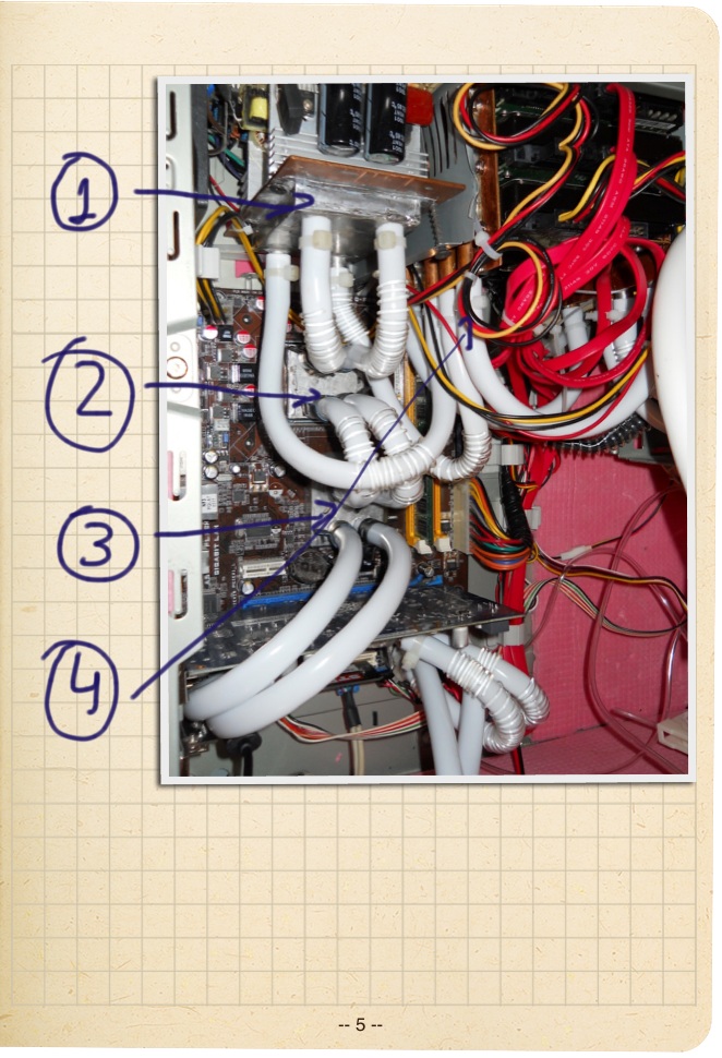
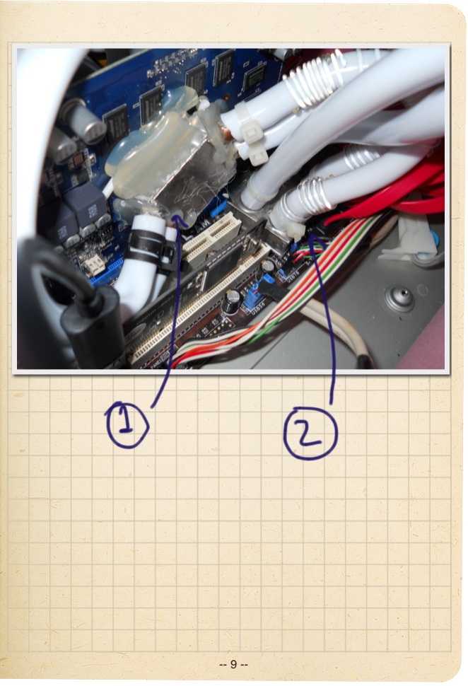
On the photo: a partial photo of the motherboard (1 is a water block on the power supply, 2 is a processor, 3 is a chip on the motherboard, 4 is a water block for screws)
Paired connection is also convenient in the situation when there is a risk of hose bends (and this was in the process of testing the system) - as a result - the reliability of the entire system is greatly increased at slightly increased costs.
The waterblock for the power supply is made according to the same scheme, only the dimensions are increased and the fields on the basis of the transistors installation are initially added. I thought I would blow out the transistors and screw them to the water block, and solder the legs with thick wires. But when disassembling the power supply, I was pleasantly surprised that the 2 radiators from the transistors have a smooth base to which the water block can be well attached. What I did with screws and hot melt glue.
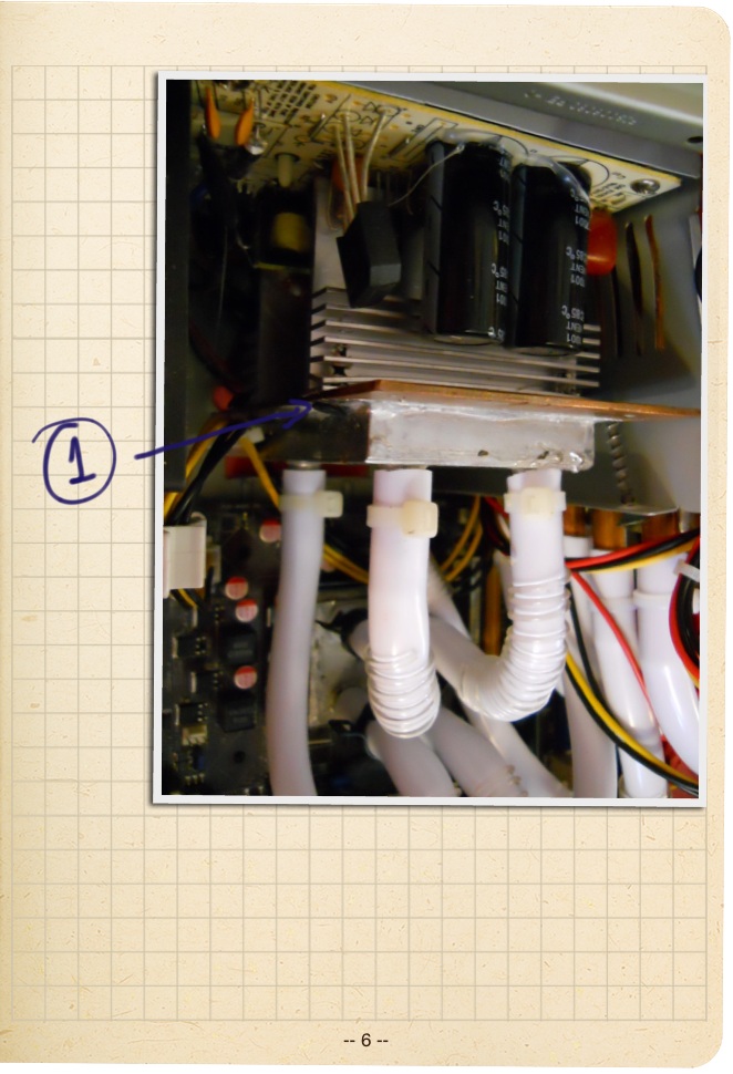
In the photo: fixing the water block for the power supply.
The leakage protection system is based on the principle of pressure reduction in the system and monitoring through a pressure gauge. At first, the pressure was kept for a week and more, but then it began to quickly level off with atmospheric pressure. But it does not matter: the testing period was long (several months) as a result of which it turned out that the leakage system does not give.
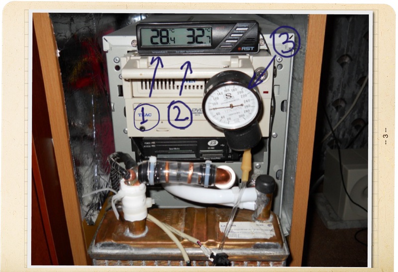
On the photo is the monitoring system (temperature sensors, pressure gauge and impeller. 1 - room temperature, 2 - in the cooling system).
The fluid flow sensor is a home-made impeller made of plastic, cut to the desired shape and glued with superglue to the needle from the syringe. Further, the needle with the impeller was worn over the sewing needle (forming a freely rotating axis) and placed along the transparent tube. Everything is ready - the water spins the impeller, and we look.

In the photo: temperature sensors glued into the nozzle and impeller, showing the flow of fluid
Well, everything was soldered, connected, checked - it works! It remains to mount and go.
With the fastener I did not suffer much - I just stuck it on the hot melt glue. According to the characteristics of the glue - it softens when heated to 70 or more degrees (this is about re-softening the glue after its initial drying), and this is the critical temperature for the chips and blocking the motherboard to turn off the power before reaching this temperature - therefore there is no serious risk that the water block will fall off due to the softening of the adhesive.
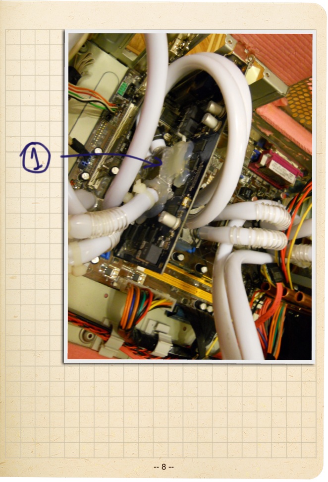
When sticking water blocks to chips, the problem was that the surface area of the chip was too small to hold the water block. To fix the waterblocks, I came up with something else: I took a hot glue (glue gun) and poured waterblocks around the perimeter (this is clearly seen in the photos). It can be said that after this, the motherboard and so on cannot be laundered, and don't care, the motherboard cost 1,500 rubles, and its cost almost does not affect the cost of the project.
in the photo: fixing the water block with hot melt adhesive (1 - water block of the video card, 2 - water block of the second motherboard chip).
Also, you need to pay attention to the bend of the hoses - I had to pack all the bends into spirals - protection against bends.
After the assembly and launch, I was shocked - the computer is not audible at all! More precisely, you can hear how the screws work - which strained at first. Noise from the pump or fans can not be heard. You can certainly listen strongly, leaning your ear to the computer. The feeling was not at all familiar: the noise level from the computer is less than the noise from the working screw.
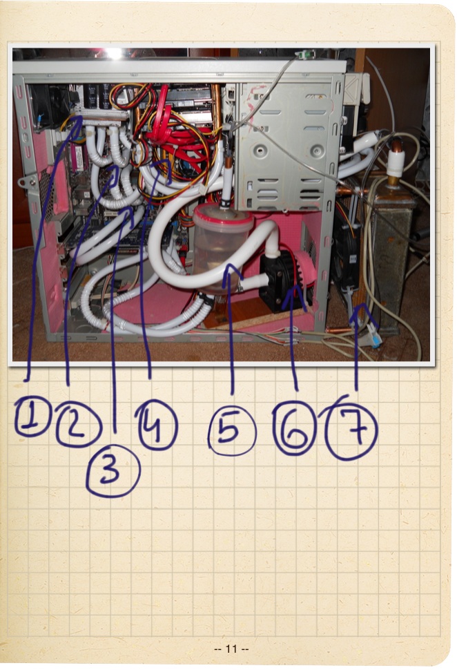
the whole system in the photo: 1 - power supply, 2 - processor, 3 - chip, 4 - basket with screws, 5 - expansion tank, 6 - pump, 7 - radiator with cooler.
After running in the system, I overclocked the processor by 20%, which had almost no effect on the temperature of the system.
Software monitoring shows that the temperature is high, about 50-55 degrees on the processor. It is not low, but not critical. Therefore, I do not bother.
The water temperature in the system rarely exceeds 43-45 degrees, this is when the computer is fully loaded for 2-3 hours and the room temperature is 28 degrees.
In general, it all took about half a year - he worked without haste, on weekends, in the kitchen and was absolutely satisfied with the result. The system has been running for two years and makes me happy and surprises friends.
Well, the last thing - if you want silence - do not buy aquarium pumps, noisy fans and fluid flow sensors with connection to a computer - all this will make the system rather noisy - do not save on silence!
')
Immediately I warn you - the goal was silence, and not a beautiful, from an aesthetic point of view, decision.
Photos will not be in the text.
The decision to install CBO on a computer was the result of many attempts to make it work a little quieter. In the process of experiments with noise reduction, I tried a lot of things: lowering the fan speed, cleaning the coolers, pasting the case with sound-absorbing materials - every time there was an effect, but too little.
As a result of these experiments, the main sources of noise were determined - coolers in the power supply and on the processor.
Changing the CPU cooler to low noise or almost silent is not a problem, but it is more difficult with the power supply: all power supplies make noises as they heat up, even very expensive ones. And there was no desire to check in practice the expensive power supply unit. Even if all the coolers are replaced with passive radiators the size of a carton of milk, then all the same this system will have to be blown with air (the heat will not leave the closed case anywhere).
One way to reduce noise is to replace the processor. At the time of the start of production, I had a Pentium 4 with 130 watts of heat, changing it to Core2Duo with a heat output of 65-75 watts, which significantly reduced the heat and, as a result, the speed of the cooler and its noise. But the decision to create ITS has already been made and it was necessary to begin.
There was an option to take ready components, but analyzing them revealed several weak points:
• Often there is a combination of copper and aluminum in the manufacture of water blocks - and this will lead to corrosion;
• Excessive high cost of water-cooled power supplies (at that time the price was over $ 500), this price calls into question the project itself;
• Kits with one waterblock for the processor (complete system) are quite noisy.
As a result, I do everything myself!
Here is a list of what I used:
• Sheet copper (0.8 mm, 1 mm, 2 mm, sheets of 200 * 200 mm in size, 2 sheets of each thickness were taken) - 2000 rubles (high price due to buying copper in the store for modellers);
• Copper tube 10 mm outer diameter (annealed water pipe from the market) - 500 rubles;
• The radiator from the volgovka stove (in its characteristics it is indicated that it can dissipate up to 16 kW of heat - and this is enough to warm the entire room, and not just cool the computer) - 1000 rubles with delivery;
• Pomp Laing D5-Pumpe 12V D5-Vario - we do not save on silence! (the most expensive single part - about 4,000 rubles at the time of purchase);
• Hoses with an internal diameter of 9.7 mm - 6 meters and springs from bending, all for 1000 rubles (bought in the store for modders and CBO systems);
• A manometer from an old tonometer - for a leakage monitoring system - 100 rubles, bought with a hammer;
• Automotive thermometer with an external sensor - 400 rubles;
• Food container with a sealed lid -100 rubles;
• Coolant - filtered water is free;
• Fan for radiator - SCYTHE S-Flex SFF21D (maximum noise level 8.7 dB) - 500 rubles.
Tool:
• Conventional hacksaw;
• Gas soldering iron (in the form of a can with a nozzle like a turbo lighter, bought in an Internet shop in China for 10 bucks);
• 60-watt electric soldering iron;
• Solder, flux, clamps and vices, needle files, wire cutters, pliers and all sorts of small things.
The approximate amount of materials and tools - 10,000 rubles at the time of purchase.
In the process was made the following:
• water block per processor (area 40 * 40 mm);
• water block per chip (35 * 35 mm) - 2 pieces;
• water block on video (35 * 35 mm);
• analogue basket for HDD (3 discs);
• water block for power supply (100 * 60 mm);
• Expansion tank made of food container with airtight lid.
Water blocks were made as follows:
• the base is copper with a thickness of 2 mm tinned from the inside;
• edges - from 20 to 40 edges (depending on the water block) of 33 * 10 mm in size for small water blocks, 38 * 10 - for the processor and 80 * 10 for the power supply unit, copper thickness is 0.8 mm;
• walls - copper 1 mm (according to the size of the base of the water block and 10 mm high);
• the top cover - copper 1 mm and the size of the base of the water block;
• Branch pipes - water pipes 30-40 mm long.
The ribs for the water blocks were tinned along the edge, the field of this extra solder (flooding, etc.) was cleaned with needle files. The prepared ribs were assembled in a block, a layer of paper was laid between the ribs (small leaves, 5-10 pieces each). With this approach, it is possible to assemble a radiator with micro channels in home-kitchen conditions. Further, the resulting block of ribs and paper fastened, or rather soldered on the end, with a thin wire. This wire ensured the integrity of the unit and its mobility (unfortunately there are no photos). After preparing the block of ribs, the tinned base was taken and lowered onto the hot plate of the plate and heated to the melting point of the solder. The resulting block of fins (greased from the bottom side with flux) was lowered onto the base with molten solder. For a couple of seconds, the flux boiled off and tightened the solder to its place from the base of the water block. The result was a normally soldered water block with a huge area of ribs (40 * 10 mm * 20-40 pieces). After the whole structure had cooled down, the assembly wire was removed from it, layers of paper between the ribs were removed and unnecessary solder flows were cleaned. As soon as the base with the ribs was ready, the side ribs and the top cover with the soldered connections were soldered to it.
On the photo is a processor water block. (1 - water block on the power supply, 2-processor, 3 - chip on the motherboard)
In the top cover 4 holes were made for inlet and outlet connections.
It turns out that the entire system has a serial connection of water blocks with paired tubes (this is seen in the pictures). Tubes between water blocks are paired due to the fact that the internal cross section of the pump tubes is larger than the cross section of the tubes between water blocks, and in order not to create additional hydroresistance, it was decided to apply such a scheme. In my case, the internal cross section of the pump tubes is approximately equal to the two internal cross sections of the tubes used. Serial connection is easier because water is guaranteed to bypass the entire cooling circuit. If you make a parallel connection of water blocks, then there is a chance that the water with a large resistance will not flow. Then this part of the circuit will be hotter.
On the photo: a partial photo of the motherboard (1 is a water block on the power supply, 2 is a processor, 3 is a chip on the motherboard, 4 is a water block for screws)
Paired connection is also convenient in the situation when there is a risk of hose bends (and this was in the process of testing the system) - as a result - the reliability of the entire system is greatly increased at slightly increased costs.
The waterblock for the power supply is made according to the same scheme, only the dimensions are increased and the fields on the basis of the transistors installation are initially added. I thought I would blow out the transistors and screw them to the water block, and solder the legs with thick wires. But when disassembling the power supply, I was pleasantly surprised that the 2 radiators from the transistors have a smooth base to which the water block can be well attached. What I did with screws and hot melt glue.
In the photo: fixing the water block for the power supply.
The leakage protection system is based on the principle of pressure reduction in the system and monitoring through a pressure gauge. At first, the pressure was kept for a week and more, but then it began to quickly level off with atmospheric pressure. But it does not matter: the testing period was long (several months) as a result of which it turned out that the leakage system does not give.
On the photo is the monitoring system (temperature sensors, pressure gauge and impeller. 1 - room temperature, 2 - in the cooling system).
The fluid flow sensor is a home-made impeller made of plastic, cut to the desired shape and glued with superglue to the needle from the syringe. Further, the needle with the impeller was worn over the sewing needle (forming a freely rotating axis) and placed along the transparent tube. Everything is ready - the water spins the impeller, and we look.
In the photo: temperature sensors glued into the nozzle and impeller, showing the flow of fluid
Well, everything was soldered, connected, checked - it works! It remains to mount and go.
With the fastener I did not suffer much - I just stuck it on the hot melt glue. According to the characteristics of the glue - it softens when heated to 70 or more degrees (this is about re-softening the glue after its initial drying), and this is the critical temperature for the chips and blocking the motherboard to turn off the power before reaching this temperature - therefore there is no serious risk that the water block will fall off due to the softening of the adhesive.
When sticking water blocks to chips, the problem was that the surface area of the chip was too small to hold the water block. To fix the waterblocks, I came up with something else: I took a hot glue (glue gun) and poured waterblocks around the perimeter (this is clearly seen in the photos). It can be said that after this, the motherboard and so on cannot be laundered, and don't care, the motherboard cost 1,500 rubles, and its cost almost does not affect the cost of the project.
in the photo: fixing the water block with hot melt adhesive (1 - water block of the video card, 2 - water block of the second motherboard chip).
Also, you need to pay attention to the bend of the hoses - I had to pack all the bends into spirals - protection against bends.
After the assembly and launch, I was shocked - the computer is not audible at all! More precisely, you can hear how the screws work - which strained at first. Noise from the pump or fans can not be heard. You can certainly listen strongly, leaning your ear to the computer. The feeling was not at all familiar: the noise level from the computer is less than the noise from the working screw.
the whole system in the photo: 1 - power supply, 2 - processor, 3 - chip, 4 - basket with screws, 5 - expansion tank, 6 - pump, 7 - radiator with cooler.
After running in the system, I overclocked the processor by 20%, which had almost no effect on the temperature of the system.
Software monitoring shows that the temperature is high, about 50-55 degrees on the processor. It is not low, but not critical. Therefore, I do not bother.
The water temperature in the system rarely exceeds 43-45 degrees, this is when the computer is fully loaded for 2-3 hours and the room temperature is 28 degrees.
In general, it all took about half a year - he worked without haste, on weekends, in the kitchen and was absolutely satisfied with the result. The system has been running for two years and makes me happy and surprises friends.
Well, the last thing - if you want silence - do not buy aquarium pumps, noisy fans and fluid flow sensors with connection to a computer - all this will make the system rather noisy - do not save on silence!
Source: https://habr.com/ru/post/155531/
All Articles