We write the Gameboy emulator, part 2
Hello!
In the previous part of this series of articles, we looked at the DMG processor and memory. The next logical step is to emulate how the DMG displays the image.
We write the Gameboy emulator, part 1
We write the Gameboy emulator, part 2
We write the Gameboy emulator, part 3
Timers
Control
Putting it all together
Testing
Conclusion
')
DMG displays the image on the screen line by line and emulates the states characteristic of CRT screens. Each state lasts a strictly defined number of cycles. It is necessary to provide access to the memory. To draw graphics, access to video memory and OAM is needed in two places at once - the LCD controller, which displays everything on the screen; game (CPU), which modifies the memory to display the frame that she needs. To solve this problem, the entire graphics output task was divided into intervals (each corresponds to a certain state), which determine the time during which the logic of the screen or the game can access the memory. There are four states in total (the numbers are not random, but strictly defined for the DMG):
When each line is drawn, the LCD controller goes through the states in this order - 2, 3, 0. After the last line is drawn, it goes to state 1. Then everything starts anew from the first line.
Drawing one line lasts exactly 456 cycles. This time is made up of the duration of states 2, 3, 0 and is always equal to 456 cycles, but the duration of the states themselves may vary. Since the screen has 144 lines, their output takes 65,664 cycles. Another 4560 cycles exactly lasts state 1. From the figure it is clear that this time is equal to 10 lines. This is true - in state 1, there are, as it were, drawing 10 more lines. The line counter (LY register) does not stop at 143, but reaches 153. As a result, a full screen update takes 70,224 cycles or 154 lines of 456 cycles.
The transition between states is accompanied by interrupt requests, if enabled. The transition to each of the four states, except the third, is accompanied by a request to interrupt the LCDC. In addition, this interrupt is requested if LY and LYC are equal. The request is carried out only if the LCDC interrupt for this state is enabled in the STAT register. Its structure is as follows:
An important detail - the LCDC interrupt can only be requested once per line.
A lot of this could be learned from the CPU Manual, but there is one thing here - not all you need to know about the operation of the LCD controller for its emulation. I did not go into all the details (in fact, I did not find them), but only stopped at what allows you to correctly display the graphics in the games I tested, and at the same time pass the test of the LCD controller.
In order to at least approximately emulate the controller, we will have to enter another set of states — internal, accessible only to our emulator. There are 8 of them:
From the names it is clear that they correspond to real states. They pass in the following order:
Intermediate states are needed for more accurate synchronization of various events. Consider each state in more detail.
LCDMODE_LYXX_OAM . When we switch to this state, we change the state in the STAT register to 2 (OAM read). Check if LCDC interrupt is enabled. If successful, we request it and mark somewhere that the LCDC interrupt can no longer be requested.
In this state, we take into account one feature of the DMG. If the SCX register is set to bit 2 (for example, the register is 4), then right now we need to note somewhere that the following states should change their duration to 4 clock cycles. This condition lasts exactly 80 cycles.
LCDMODE_LYXX_OAMRAM . Change the STAT state to 3. LCDC no interrupt. So far we have not dealt with the topic of sprites, but this is where the function call will be, which is the queue of sprites that will be later displayed on this line.
This is another DMG feature. Spriting output changes the duration of the states. The more of them, the longer the state 3 lasts and the shorter the state 0 (we need to keep within 456 cycles, so everything is proportional). DMG can display a maximum of 10 sprites in one line, so we have enough of an array of 11 elements with values that indicate a change in the duration of the states. It should contain the following values:
This state lasts 172 cycles + number of cycles due to the SCX register + number of cycles due to sprites. For example, if the SCX register in the previous state was equal to 4, and the sprites are displayed 6, then the duration of the state will be equal to 172 + 4 + 64 cycles.
LCDMODE_LYXX_HBLANK . Here we draw the current line, which can be learned from the LY register. We note the state 0 in the STAT register. We request the LCDC interrupt if it has not yet been requested.
The length of the clock is calculated as follows: 200 clocks - clocks due to SCX - clocks due to sprites. Thus, here we compensate for the shift in duration that occurred in the LCDMODE_LYXX_OAMRAM state.
LCDMODE_LYXX_HBLANK_INC . Here we increase the register LY by one - it is a row counter. Reset the flag, which indicates that the LCDC interrupt has already been requested (we are moving to the next line). Here we need to check for equality registers LY and LYC. Here is the approximate pseudocode:
The LYC register is used by games to track when LY reaches a certain value. He has no other appointments.
This state lasts 4 bars. Which state the transition will take is dependent on the value of LY. Everything is indicated in the table above.
LY9X_VBLANK . If we have passed to this state and LY is equal to 144, then we need to somehow cancel, that we have passed into the V-blank state. Set the state in STAT 1. We request an interrupt V-blank. Here you must again request the LCDC interrupt, if allowed. Thus, two interrupts may be requested here. If LY is not equal to 144, then nothing needs to be done, because we are already in V-blank.
This state lasts exactly 452 cycles.
LY9X_VBLANK_INC . Here we need to increment LY and check for equality of LY and LYC, as we did before. Here we must take into account that with LY equal to 153, we move to another state, and do not start anew with LY9X_VBLANK - see the table.
This state lasts 4 cycles.
LY00_VBLANK . Here we need to reset LY.
This state lasts 452 cycles.
LCDMODE_LY00_HBLANK . This is the last in the frame and rather strange condition. It lasts only 4 cycles and sets the STAT state to state 0. After it, everything starts anew.
Everything, with a cycle of states is over. Now a small, but very important detail. If you read the description of the register LCDC, then you might notice that bit 7 is responsible for on / off display. We need to somehow reflect this in our states.
If the game has turned off the display, then we need to reset the LY register, and set the state to STAT in the STAT register. If the game has turned on the display (a prerequisite - before that it had to be turned off), then we need to return the controller to its very initial state - all clock counters set to zero, LY is zero, state 2 is current. we start the whole cycle of states from the very beginning. Many games refuse to work without these manipulations. An example of such a game is Bomb Jack. She refuses to reach even the initial menu.
I do not accidentally give examples of games. Test ROMs are good, but passing them does not guarantee the correct operation of games, and not all of them check. Where possible, I will give the name of the games that are recommended to check on my emulator. Bomb Jack is a must-check - many games do such tricks with turning off the screen.
In all components, the synchronization will look roughly the same. We get the clock counter, to which we will add the last bars. As soon as the value has reached the necessary, we subtract this number from it (we do not reset it, because more cycles could take place than we need) and we do what is needed.
This is what our synchronization function in Cookieboy :: GPU will look like:
Naturally this is only a part, but it is enough. And so, ClockCounter serves as a counter. Next we have a while construct that checks whether the counter has reached the desired value. The variable ClocksToNextState is used to store the number of ticks that must pass before the onset of the new state. We subtract them from the counter so that it continues to count to the next state.
Why here while? It is important. Some states last only 4 bars and it is quite possible that this state can occur immediately. Those. we set ClocksToNextState equal to 4, and in our counter there are already 4 clocks. In order not to wait for an extra call to the synchronization function, we will process the new event right there, at the next iteration of the cycle. This approach should be taken as a rule where the intervals between states (events) are too small and may be less than the duration of a single processor instruction.
Next we see the condition with the macro LCD_ON (). Here we check if the display is turned off. If so, then we do not go through the entire cycle of states. We are only clearing the screen and are waiting for 70224 bars for the one full screen update.
If the display is turned on, then using the switch construction, we perform the necessary actions for the current state. The specificity of my implementation is that we store in the LCDMode not so much the current, as the next state. After completing the necessary actions, we set the following state in LCDMode and show how many clock cycles it should go through. Yes, LCDMode is only an auxiliary variable, it does not exist for games. Real states are stored in the STAT register, where they should.
The graphics output is carried out in three stages in the following order:
As you can see, if we go beyond the boundaries of the background, then we find ourselves at its opposite end. Background zaylen, as they often say.
All information about the tiles and their content is in the video memory. Here is its structure:
Tiles are stored first. DMG can store up to 384 tiles divided into two sets of 256 tiles each, so that half of them are common. One set uses numbers from 0 to 255 to designate tiles. The numbers from -128 to 127 use the other. The background itself is drawn according to the selected tile map. They are also two. They are 1024 bytes in size - one byte per tile number.
Selecting a set of tiles and tile maps is carried out using the register LCDC. There is also a flag on / off displaying the background. Here, by the way, its structure:
Tiles themselves occupy 16 bytes in memory. Every 2 bytes are responsible for one line, thus giving us 8x8 tiles. The organization of tiles in memory is rather strange, as shown below:

The color of a pixel is composed of two bits, where the low bit is taken from the first byte, and the high bit from the second. As a result, color indices are obtained, which can have 4 values: from 0 to 3. These indices are used to select a color from the palette in the BGP register. Here is its structure:
That is, having a pixel color equal to 2, we look at the BGP register value of bits 5-4, which give us a color that can also have 4 values from 0 to 3. This leads us to the need to have another palette to translate colors from the DMG palette to real RGB colors for later output. This applies to the entire graph as a whole.
You can use a black and white palette, which gives us the following colors:
Or use colors that are closer to those on the screen of this DMG:
A color with a value of 0 (the brightest) is used to clear the screen. Accordingly, if the screen needs to be cleared or the background is turned off, then simply fill it with color with the index 0.
The figure below shows an example of a “window” output at WX = 87 and WY = 70.

Before outputting, you need to check not only the “window” output flag in the LCDC, but also the coordinates:
An important detail. WX and WY are subject to change during the withdrawal process. WX changes will take effect when the next line is displayed, but WY changes will take effect only on the next screen update.
As I said, in many ways the output of the “window” is identical to the background output, but there is one major difference.
To display it, use the hidden pointer of the current row of the "window", which is incremented after the output of the next row. If the “window” is disabled or hidden due to the WX / WY coordinates, then its row counter is not incremented. Thus, if the “window” output was turned off halfway, then when the output is turned on, the output will continue from the place where it stopped. This is valid for one screen refresh. At the end of the V-blank, the row counter of the “window” is reset.
In addition, the counter value changes when the LCDC is modified. If the "window" was turned off, and now turned on by means of LCDC, then its output will begin only on the next screen update from the first line.
At least one game uses this DMG feature - Ant Soldiers. Immediately after launching, game authors should be displayed at the bottom of the screen. If the above-mentioned features do not take into account the mentioned features, then at the bottom of the screen it will be empty. But even worse is that the game interface will also not be visible, which is why a normal game is no longer possible.
Sprites can be 8x8 or 8x16, i.e. one or two tiles controlled by a flag in the LCDC register. Sprite information is in the OAM area. There are 4 bytes per sprite, which allows you to store up to 40 sprites in OAM. These bytes contain the following information:
Sprite coordinates are for the lower right corner. The coordinates of the upper left corner are X-8 and Y-16. The size of the sprite here does not matter.
For a tile number it is very important to consider the size of the sprite. If it is set as 8x16, then the least significant bit in the tile number must be cleared, otherwise the graphics output in some games will be incorrect.
If the priority is set to 1, then the sprite is drawn as if behind the background and the “window”. Sprite pixels are drawn only on top of colors that have a value of zero. To do this, you need to display the background and the "window", and then check the color of the pixel, where we are going to display the sprite. Sprite as it "appears through" through the pixels with zero color. If the priority is set to 0, then the sprite is drawn over the background and the “window”.
With reflection everything is clear. There are two palettes for sprites (OBP0 and OBP1), they play the same role with the exception that the color index 0 (bits 0-1 in the palette) means a transparent pixel and its color in the palette does not matter.
Before you render sprites, you need to know exactly what should be displayed and in what order. Sprites have a priority that dictates the order in which they are displayed on the screen. It is calculated this way - the sprites are displayed in the order of their X coordinates, from large to smaller. Those. Sprites with a smaller value of the X coordinate are displayed on top of those with a large X value. If the X coordinates are equal, then the priority is calculated according to the order in OAM — sprites with a smaller address in OAM will be higher.
To determine whether to render a sprite, you need to check the Y coordinate of the OAM. It should be such that the sprite falls on the current line:

where LY is the current line of the screen, and SpriteHeight is the height of the sprite (8 or 16). This is a very important formula - improperly forming a sprite queue will lead to subtle bugs in some games (many games can work fine, as I did). First we transfer the Y coordinate - as already mentioned, the coordinates of the sprites point to their lower right corner. Again, the height of the sprite does not affect these calculations specifically, but to form an interval in which the value of the current line may lie, we already need to take into account the height of the sprite.
X coordinate can be any, even if it leads to the fact that the sprite will not be visible on the screen - it still falls into the list.
Sprites are displayed according to their priority, but no more than 10 pieces on one line. Thus, invisible because of the X coordinate sprites fall into the list and thereby limit the possible number of sprites on a given line of the screen. Accordingly, when displaying sprites on the screen, you need to be prepared for the fact that they may lie outside of it.
As for the limit of 10 pieces - I have not found reliable information on how to consider this limitation. There may be two logical solutions:
I chose the second option, since other emulators use it. Testing in games did not help with the solution - there were no visible bugs of any of the implementations.
Most of all the problems I probably delivered the game Gameboy Wars Turbo. I was able to achieve the right picture in it only at the time of writing this series of articles. There are other good test games. Ant Soldiers I have already mentioned.Kirbys Pinball Land is well suited for testing sprite output - an introductory video uses sprites of various sizes.
As usual, we declare all the registers we need, we give access to them from outside (specifically, for the class Cookieboy :: Memory). With video memory and OAM a bit more complicated.
, , STAT. – ( ) ( ). , . , , . – . LCD- ( Gameboy CPU Manual), . , .
, , . – , . , , RGB .
. (LY) , , «» — void Cookieboy::GPU::RenderScanline(). — void Cookieboy::GPU::PrepareSpriteQueue(). LCD- , .
, – (, , ), . – . . – , .
Let's sum up. . , ROM' . , DMG – .
, DIV, 16384 (.. 256 ). , . DIV. DIV 0 255. .. 255, 0. DIV - , .
, TIMA, . :
, DIV, . while (, ) LCD-. 262144 16 , , . , , - . .
, ROM'. – .
, DMG 8 : 4- , A B, Start Select. , , DMG P1. :
, , . , P13, P12, P11, P10. P15 P14 ROM' , , P1. :
In this register, a bit with a value of 0 means that the key is pressed. If the key is pressed, the corresponding interrupt is requested. It is this interrupt that brings DMG out of stop due to the execution of the STOP instruction. In this state, the main components do not work, and interrupts are not requested. Only clicking on a button can request it. In my emulator, the STOP instruction is ignored - the games work fine, and test ROMs do not check it.
The implementation comes down to querying the state of the keys that emulate the DMG buttons, and setting the corresponding bits according to the values in P15 and P14. But there are some nuances.
(, , ) , , – . , . . Which one , – 70224 . . , P1 .
– . 70224 , 4194304 , DMG 59.73 , 60 .
, 70224 . , . , . , «» , 1000/60 . .
, .
, . , . , . ROM'.
, , . . — , , . , .
. . 11 . , . , , . POP AF, DAA HALT. POP AF – , . , - F. DAA - . HALT . CPU Manual …
– ROM - . DMG, , .
, . , , . Readme .
, 255. , , – ROM . . Readme, , . , .
. , . , , . , . , . , . , ( ) . .
, LCD. , LCD-, (, LY). , OAM . / 7 LCDC. , ROM' .
, . . , , .
In the previous part of this series of articles, we looked at the DMG processor and memory. The next logical step is to emulate how the DMG displays the image.
We write the Gameboy emulator, part 1
We write the Gameboy emulator, part 2
We write the Gameboy emulator, part 3
Table of contents
DisplayTimers
Control
Putting it all together
Testing
Conclusion
')
Display
At this stage, we need to emulate how the DMG displays the image on the screen. Everything will be in the class Cookieboy :: GPU ( link to the source code Cookieboy). The task can be divided into two large parts - emulation of the specifics of how the DMG draws a picture; emulation of logic that controls the screen.LCD controller. Theory
Let's start with logic, because it is she who will dictate when and what to draw. As always, before implementation we need to understand how the component works.DMG displays the image on the screen line by line and emulates the states characteristic of CRT screens. Each state lasts a strictly defined number of cycles. It is necessary to provide access to the memory. To draw graphics, access to video memory and OAM is needed in two places at once - the LCD controller, which displays everything on the screen; game (CPU), which modifies the memory to display the frame that she needs. To solve this problem, the entire graphics output task was divided into intervals (each corresponds to a certain state), which determine the time during which the logic of the screen or the game can access the memory. There are four states in total (the numbers are not random, but strictly defined for the DMG):
- 0. H-blank. For CRT screens, it means that at this moment the scanning beam goes to the beginning of the next line. In DMG, of course, there are no rays. This state means two things. First, one line was output. Secondly, the video memory and OAM are not used by the LCD controller and are accessible by the CPU.
- 1. V-blank. Another state from the world of CRT, which means the moment when the beam reached the end of the last line and goes to the beginning of the first line. For us, it means two things. First, all 144 visible lines were displayed. Secondly, the video memory and OAM are not used by the LCD controller and are accessible by the CPU.
- 2. OAM. This status means that the LCD controller uses OAM memory. CPU is not available, but video memory is still available.
- 3. OAMRAM. This status means that the LCD controller uses OAM and video memory. CPU they are not available.
When each line is drawn, the LCD controller goes through the states in this order - 2, 3, 0. After the last line is drawn, it goes to state 1. Then everything starts anew from the first line.
Drawing one line lasts exactly 456 cycles. This time is made up of the duration of states 2, 3, 0 and is always equal to 456 cycles, but the duration of the states themselves may vary. Since the screen has 144 lines, their output takes 65,664 cycles. Another 4560 cycles exactly lasts state 1. From the figure it is clear that this time is equal to 10 lines. This is true - in state 1, there are, as it were, drawing 10 more lines. The line counter (LY register) does not stop at 143, but reaches 153. As a result, a full screen update takes 70,224 cycles or 154 lines of 456 cycles.
The transition between states is accompanied by interrupt requests, if enabled. The transition to each of the four states, except the third, is accompanied by a request to interrupt the LCDC. In addition, this interrupt is requested if LY and LYC are equal. The request is carried out only if the LCDC interrupt for this state is enabled in the STAT register. Its structure is as follows:
| Bits | Purpose |
| 6 | Allow LCDC interrupt in case of equality of registers LY and LYC |
| five | Allow LCDC interrupt on going to state 2 |
| four | Allow LCDC interrupt on going to state 1 |
| 3 | Allow LCDC interrupt on going to state 0 |
| 2 | A bit is set if LY and LYC are equal. Reset otherwise |
| 0-1 | Current state |
An important detail - the LCDC interrupt can only be requested once per line.
A lot of this could be learned from the CPU Manual, but there is one thing here - not all you need to know about the operation of the LCD controller for its emulation. I did not go into all the details (in fact, I did not find them), but only stopped at what allows you to correctly display the graphics in the games I tested, and at the same time pass the test of the LCD controller.
In order to at least approximately emulate the controller, we will have to enter another set of states — internal, accessible only to our emulator. There are 8 of them:
enum InternalLCDModes { LCDMODE_LY00_HBLANK, LCDMODE_LYXX_HBLANK, LCDMODE_LYXX_HBLANK_INC, LCDMODE_LY00_VBLANK, LCDMODE_LY9X_VBLANK, LCDMODE_LY9X_VBLANK_INC, LCDMODE_LYXX_OAM, LCDMODE_LYXX_OAMRAM }; From the names it is clear that they correspond to real states. They pass in the following order:
| Line | States |
| 0 | LYXX_OAM -> LYXX_OAMRAM -> LYXX_HBLANK -> LYXX_HBLANK_INC |
| one | LYXX_OAM -> LYXX_OAMRAM -> LYXX_HBLANK -> LYXX_HBLANK_INC |
| ... | ... |
| 143 | LYXX_OAM -> LYXX_OAMRAM -> LYXX_HBLANK -> LYXX_HBLANK_INC |
| 144 | LY9X_VBLANK -> LY9X_VBLANK_INC |
| ... | ... |
| 152 | LY9X_VBLANK -> LY9X_VBLANK_INC |
| 153 | LY00_VBLANK -> LY00_HBLANK |
Intermediate states are needed for more accurate synchronization of various events. Consider each state in more detail.
LCDMODE_LYXX_OAM . When we switch to this state, we change the state in the STAT register to 2 (OAM read). Check if LCDC interrupt is enabled. If successful, we request it and mark somewhere that the LCDC interrupt can no longer be requested.
In this state, we take into account one feature of the DMG. If the SCX register is set to bit 2 (for example, the register is 4), then right now we need to note somewhere that the following states should change their duration to 4 clock cycles. This condition lasts exactly 80 cycles.
LCDMODE_LYXX_OAMRAM . Change the STAT state to 3. LCDC no interrupt. So far we have not dealt with the topic of sprites, but this is where the function call will be, which is the queue of sprites that will be later displayed on this line.
This is another DMG feature. Spriting output changes the duration of the states. The more of them, the longer the state 3 lasts and the shorter the state 0 (we need to keep within 456 cycles, so everything is proportional). DMG can display a maximum of 10 sprites in one line, so we have enough of an array of 11 elements with values that indicate a change in the duration of the states. It should contain the following values:
| Number of sprites | 0 | one | 2 | 3 | four | five | 6 | 7 | eight | 9 | ten |
| So you | 0 | eight | 20 | 32 | 44 | 52 | 64 | 76 | 88 | 96 | 108 |
This state lasts 172 cycles + number of cycles due to the SCX register + number of cycles due to sprites. For example, if the SCX register in the previous state was equal to 4, and the sprites are displayed 6, then the duration of the state will be equal to 172 + 4 + 64 cycles.
LCDMODE_LYXX_HBLANK . Here we draw the current line, which can be learned from the LY register. We note the state 0 in the STAT register. We request the LCDC interrupt if it has not yet been requested.
The length of the clock is calculated as follows: 200 clocks - clocks due to SCX - clocks due to sprites. Thus, here we compensate for the shift in duration that occurred in the LCDMODE_LYXX_OAMRAM state.
LCDMODE_LYXX_HBLANK_INC . Here we increase the register LY by one - it is a row counter. Reset the flag, which indicates that the LCDC interrupt has already been requested (we are moving to the next line). Here we need to check for equality registers LY and LYC. Here is the approximate pseudocode:
LY == LYC 2 STAT 2 STAT LCDC , 2 STAT The LYC register is used by games to track when LY reaches a certain value. He has no other appointments.
This state lasts 4 bars. Which state the transition will take is dependent on the value of LY. Everything is indicated in the table above.
LY9X_VBLANK . If we have passed to this state and LY is equal to 144, then we need to somehow cancel, that we have passed into the V-blank state. Set the state in STAT 1. We request an interrupt V-blank. Here you must again request the LCDC interrupt, if allowed. Thus, two interrupts may be requested here. If LY is not equal to 144, then nothing needs to be done, because we are already in V-blank.
This state lasts exactly 452 cycles.
LY9X_VBLANK_INC . Here we need to increment LY and check for equality of LY and LYC, as we did before. Here we must take into account that with LY equal to 153, we move to another state, and do not start anew with LY9X_VBLANK - see the table.
This state lasts 4 cycles.
LY00_VBLANK . Here we need to reset LY.
This state lasts 452 cycles.
LCDMODE_LY00_HBLANK . This is the last in the frame and rather strange condition. It lasts only 4 cycles and sets the STAT state to state 0. After it, everything starts anew.
Everything, with a cycle of states is over. Now a small, but very important detail. If you read the description of the register LCDC, then you might notice that bit 7 is responsible for on / off display. We need to somehow reflect this in our states.
If the game has turned off the display, then we need to reset the LY register, and set the state to STAT in the STAT register. If the game has turned on the display (a prerequisite - before that it had to be turned off), then we need to return the controller to its very initial state - all clock counters set to zero, LY is zero, state 2 is current. we start the whole cycle of states from the very beginning. Many games refuse to work without these manipulations. An example of such a game is Bomb Jack. She refuses to reach even the initial menu.
I do not accidentally give examples of games. Test ROMs are good, but passing them does not guarantee the correct operation of games, and not all of them check. Where possible, I will give the name of the games that are recommended to check on my emulator. Bomb Jack is a must-check - many games do such tricks with turning off the screen.
LCD controller. Implementation
Finally, we can proceed to the implementation of the considered theory. As I said, in our emulator we need to synchronize all the other components with the processor - the LCD controller is not an exception. To do this, we will create a function in the class Cookieboy :: GPU, which takes as input the number of cycles that have passed. Here we will implement everything related to the change of states.In all components, the synchronization will look roughly the same. We get the clock counter, to which we will add the last bars. As soon as the value has reached the necessary, we subtract this number from it (we do not reset it, because more cycles could take place than we need) and we do what is needed.
This is what our synchronization function in Cookieboy :: GPU will look like:
void Cookieboy::GPU::Step(DWORD clockDelta, Interrupts &INT) { ClockCounter += clockDelta; while (ClockCounter >= ClocksToNextState) { ClockCounter -= ClocksToNextState; if (!LCD_ON()) { LY = 0; // ClocksToNextState = 70224; continue; } switch (LCDMode) { case LCDMODE_LY00_VBLANK: LY = 0; LCDMode = LCDMODE_LY00_HBLANK; ClocksToNextState = 452; break; } } } Naturally this is only a part, but it is enough. And so, ClockCounter serves as a counter. Next we have a while construct that checks whether the counter has reached the desired value. The variable ClocksToNextState is used to store the number of ticks that must pass before the onset of the new state. We subtract them from the counter so that it continues to count to the next state.
Why here while? It is important. Some states last only 4 bars and it is quite possible that this state can occur immediately. Those. we set ClocksToNextState equal to 4, and in our counter there are already 4 clocks. In order not to wait for an extra call to the synchronization function, we will process the new event right there, at the next iteration of the cycle. This approach should be taken as a rule where the intervals between states (events) are too small and may be less than the duration of a single processor instruction.
Next we see the condition with the macro LCD_ON (). Here we check if the display is turned off. If so, then we do not go through the entire cycle of states. We are only clearing the screen and are waiting for 70224 bars for the one full screen update.
If the display is turned on, then using the switch construction, we perform the necessary actions for the current state. The specificity of my implementation is that we store in the LCDMode not so much the current, as the next state. After completing the necessary actions, we set the following state in LCDMode and show how many clock cycles it should go through. Yes, LCDMode is only an auxiliary variable, it does not exist for games. Real states are stored in the STAT register, where they should.
Graphics. Theory
DMG does not handle pixels, but tiles. Naturally, the graphics are displayed pixel by pixel, but the unit for the programmer is exactly the tile, the size of which is 8x8 pixels. Thus, it is not the pixel colors that are stored in the memory, but tile numbers. These numbers refer to another area of memory where information about tiles is located - what color pixels do they consist of. The obvious goal of this approach is to save memory. It looks like the implementation of indexed colors.The graphics output is carried out in three stages in the following order:
- Background
- The so-called "window" (window)
- Sprites
Background
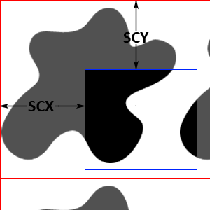
The background of a DMG is 32x32 tiles or 256x256 pixels, which is obviously larger than the DMG screen. Using the SCX and SCY registers, we can specify which part to display, as shown in the figure below.As you can see, if we go beyond the boundaries of the background, then we find ourselves at its opposite end. Background zaylen, as they often say.
All information about the tiles and their content is in the video memory. Here is its structure:
| Section | Purpose |
| 0x8000-0x87FF | A set of tiles number 1: tiles [0, 127] |
| 0x8800-0x8FFF | A set of tiles number 1: tiles [128, 255] A set of tiles number 0: tiles [-128, -1] |
| 0x9000-0x97FF | A set of tiles number 0: tiles [0, 127] |
| 0x9800-0x9BFF | Tile map number 0 |
| 0x9C00-0x9FFF | Tile map number 1 |
Tiles are stored first. DMG can store up to 384 tiles divided into two sets of 256 tiles each, so that half of them are common. One set uses numbers from 0 to 255 to designate tiles. The numbers from -128 to 127 use the other. The background itself is drawn according to the selected tile map. They are also two. They are 1024 bytes in size - one byte per tile number.
Selecting a set of tiles and tile maps is carried out using the register LCDC. There is also a flag on / off displaying the background. Here, by the way, its structure:
| Bits | Purpose |
| 7 | LCD controller control: 0: off (screen is blank) 1: on |
| 6 | Select a tile map for the "window": 0: Tile map number 0 (0x9800-0x9BFF) 1: Tile map number 1 (0x9C00-0x9FFF) |
| five | Flag display "window": 0: off 1: on |
| four | Select a set of tiles for the background and "window": 0: Tile Set No. 0 (0x8800-0x97FF) 1: Number 1 tile set (0x8000-0x8FFF) |
| 3 | Selecting a tile map for the background: 0: Tile map number 0 (0x9800-0x9BFF) 1: Tile map number 1 (0x9C00-0x9FFF) |
| 2 | Sprites size: 0: 8x8 1: 8:16 |
| one | Flag display sprites: 0: off 1: on |
| 0 | Background display flag: 0: off 1: on |
Tiles themselves occupy 16 bytes in memory. Every 2 bytes are responsible for one line, thus giving us 8x8 tiles. The organization of tiles in memory is rather strange, as shown below:
The color of a pixel is composed of two bits, where the low bit is taken from the first byte, and the high bit from the second. As a result, color indices are obtained, which can have 4 values: from 0 to 3. These indices are used to select a color from the palette in the BGP register. Here is its structure:
| Bits | Color index |
| 7-6 | 3 |
| 5-4 | 2 |
| 3-2 | one |
| 1-0 | 0 |
That is, having a pixel color equal to 2, we look at the BGP register value of bits 5-4, which give us a color that can also have 4 values from 0 to 3. This leads us to the need to have another palette to translate colors from the DMG palette to real RGB colors for later output. This applies to the entire graph as a whole.
You can use a black and white palette, which gives us the following colors:
| Color in the palette | RGB channel value |
| 0 | 0xFF, 0xFF, 0xFF |
| one | 0xAA, 0xAA, 0xAA |
| 2 | 0x55, 0x55, 0x55 |
| 3 | 0x00, 0x00, 0x00 |
Or use colors that are closer to those on the screen of this DMG:
| Color in the palette | RGB channel value |
| 0 | 0xE1, 0xF7, 0xD1 |
| one | 0x87, 0xC3, 0x72 |
| 2 | 0x33, 0x70, 0x53 |
| 3 | 0x09, 0x20, 0x21 |
A color with a value of 0 (the brightest) is used to clear the screen. Accordingly, if the screen needs to be cleared or the background is turned off, then simply fill it with color with the index 0.
Window
After displaying the background, you must display the "window". It is displayed almost the same as the background - from the LCDC we will find out which card and tile set to use. There is also a flag on / off output. It is displayed according to the coordinates specified in the registers WY and WX. But in order to display the “window” in the upper left corner of the screen, you must specify the coordinates WX = 7 and WY = 0. Ie The X and Y coordinates of the upper left corner of the “window” are WX-7 and WY, respectively.The figure below shows an example of a “window” output at WX = 87 and WY = 70.
Before outputting, you need to check not only the “window” output flag in the LCDC, but also the coordinates:
- if WX is greater than 166, then the “window” is hidden outside the screen;
- if WY is greater than 143, then the “window” is also hidden.
An important detail. WX and WY are subject to change during the withdrawal process. WX changes will take effect when the next line is displayed, but WY changes will take effect only on the next screen update.
As I said, in many ways the output of the “window” is identical to the background output, but there is one major difference.
To display it, use the hidden pointer of the current row of the "window", which is incremented after the output of the next row. If the “window” is disabled or hidden due to the WX / WY coordinates, then its row counter is not incremented. Thus, if the “window” output was turned off halfway, then when the output is turned on, the output will continue from the place where it stopped. This is valid for one screen refresh. At the end of the V-blank, the row counter of the “window” is reset.
In addition, the counter value changes when the LCDC is modified. If the "window" was turned off, and now turned on by means of LCDC, then its output will begin only on the next screen update from the first line.
At least one game uses this DMG feature - Ant Soldiers. Immediately after launching, game authors should be displayed at the bottom of the screen. If the above-mentioned features do not take into account the mentioned features, then at the bottom of the screen it will be empty. But even worse is that the game interface will also not be visible, which is why a normal game is no longer possible.
Sprites
Now came the turn of the sprites. They also consist of tiles, but are displayed completely differently.Sprites can be 8x8 or 8x16, i.e. one or two tiles controlled by a flag in the LCDC register. Sprite information is in the OAM area. There are 4 bytes per sprite, which allows you to store up to 40 sprites in OAM. These bytes contain the following information:
| Byte | Purpose |
| 0 | Y coordinate |
| one | X coordinate |
| 2 | Tile number (0-255) |
| 3 | Bit 7: priority Bit 6: Vertical Mirror Image, if 1 Bit 5: mirror image horizontally, if 1 Bit 4: if 1, use the OBJ1 palette, otherwise - OBJ0 |
Sprite coordinates are for the lower right corner. The coordinates of the upper left corner are X-8 and Y-16. The size of the sprite here does not matter.
For a tile number it is very important to consider the size of the sprite. If it is set as 8x16, then the least significant bit in the tile number must be cleared, otherwise the graphics output in some games will be incorrect.
If the priority is set to 1, then the sprite is drawn as if behind the background and the “window”. Sprite pixels are drawn only on top of colors that have a value of zero. To do this, you need to display the background and the "window", and then check the color of the pixel, where we are going to display the sprite. Sprite as it "appears through" through the pixels with zero color. If the priority is set to 0, then the sprite is drawn over the background and the “window”.
With reflection everything is clear. There are two palettes for sprites (OBP0 and OBP1), they play the same role with the exception that the color index 0 (bits 0-1 in the palette) means a transparent pixel and its color in the palette does not matter.
Before you render sprites, you need to know exactly what should be displayed and in what order. Sprites have a priority that dictates the order in which they are displayed on the screen. It is calculated this way - the sprites are displayed in the order of their X coordinates, from large to smaller. Those. Sprites with a smaller value of the X coordinate are displayed on top of those with a large X value. If the X coordinates are equal, then the priority is calculated according to the order in OAM — sprites with a smaller address in OAM will be higher.
To determine whether to render a sprite, you need to check the Y coordinate of the OAM. It should be such that the sprite falls on the current line:
where LY is the current line of the screen, and SpriteHeight is the height of the sprite (8 or 16). This is a very important formula - improperly forming a sprite queue will lead to subtle bugs in some games (many games can work fine, as I did). First we transfer the Y coordinate - as already mentioned, the coordinates of the sprites point to their lower right corner. Again, the height of the sprite does not affect these calculations specifically, but to form an interval in which the value of the current line may lie, we already need to take into account the height of the sprite.
X coordinate can be any, even if it leads to the fact that the sprite will not be visible on the screen - it still falls into the list.
Sprites are displayed according to their priority, but no more than 10 pieces on one line. Thus, invisible because of the X coordinate sprites fall into the list and thereby limit the possible number of sprites on a given line of the screen. Accordingly, when displaying sprites on the screen, you need to be prepared for the fact that they may lie outside of it.
As for the limit of 10 pieces - I have not found reliable information on how to consider this limitation. There may be two logical solutions:
- Queuing (passage through the OAM content) from all sprites that are visible according to the Y coordinate - now there can be more than 10. Then sorting and only after that discarding the extra sprites. It is logical to throw out sprites with a lower priority.
- Queuing stops when 10 sprites are cast. Thus, it may turn out that there are visible higher-priority sprites in OAM, but we have not reached them.
I chose the second option, since other emulators use it. Testing in games did not help with the solution - there were no visible bugs of any of the implementations.
Graphics. Implementation
Here we come to another crucial stage in the creation of an emulator. The slightest mistake here can lead to terrible consequences on the screen. Some errors I found only in the process of writing these articles. Before that, we had to observe complete chaos on the screen in some games.Most of all the problems I probably delivered the game Gameboy Wars Turbo. I was able to achieve the right picture in it only at the time of writing this series of articles. There are other good test games. Ant Soldiers I have already mentioned.Kirbys Pinball Land is well suited for testing sprite output - an introductory video uses sprites of various sizes.
As usual, we declare all the registers we need, we give access to them from outside (specifically, for the class Cookieboy :: Memory). With video memory and OAM a bit more complicated.
, , STAT. – ( ) ( ). , . , , . – . LCD- ( Gameboy CPU Manual), . , .
, , . – , . , , RGB .
. (LY) , , «» — void Cookieboy::GPU::RenderScanline(). — void Cookieboy::GPU::PrepareSpriteQueue(). LCD- , .
, – (, , ), . – . . – , .
Let's sum up. . , ROM' . , DMG – .
Timers
, ., DIV, 16384 (.. 256 ). , . DIV. DIV 0 255. .. 255, 0. DIV - , .
, TIMA, . :
- TIMA . , 255 , DIV. , TIMA 0, TMA.
- TMA TIMA 255.
- TAC . .
| Purpose | |
| 2 | : 0 – 1 – |
| 0-1 | : 00 – 4096 01 – 262144 10 – 65536 11 – 16384 |
, DIV, . while (, ) LCD-. 262144 16 , , . , , - . .
, ROM'. – .
Control
, DMG 8 : 4- , A B, Start Select. , , DMG P1. :
| Bit | Purpose |
| five | P15 |
| four | P14 |
| 3 | P13 |
| 2 | P12 |
| one | P11 |
| 0 | P10 |
, , . , P13, P12, P11, P10. P15 P14 ROM' , , P1. :
| P15 | P14 | P13 | P12 | P11 | P10 |
| one | 0 | Way down | Up | ||
| 0 | one | Start | Select | B | A |
In this register, a bit with a value of 0 means that the key is pressed. If the key is pressed, the corresponding interrupt is requested. It is this interrupt that brings DMG out of stop due to the execution of the STOP instruction. In this state, the main components do not work, and interrupts are not requested. Only clicking on a button can request it. In my emulator, the STOP instruction is ignored - the games work fine, and test ROMs do not check it.
The implementation comes down to querying the state of the keys that emulate the DMG buttons, and setting the corresponding bits according to the values in P15 and P14. But there are some nuances.
(, , ) , , – . , . . Which one , – 70224 . . , P1 .
– . 70224 , 4194304 , DMG 59.73 , 60 .
, 70224 . , . , . , «» , 1000/60 . .
, .
, . , . , . ROM'.
Testing
DMG ROM', DMG: , , , LCD. ROM . . , , , LCD., , . . — , , . , .
. . 11 . , . , , . POP AF, DAA HALT. POP AF – , . , - F. DAA - . HALT . CPU Manual …
– ROM - . DMG, , .
, . , , . Readme .
, 255. , , – ROM . . Readme, , . , .
. , . , , . , . , . , . , ( ) . .
, LCD. , LCD-, (, LY). , OAM . / 7 LCDC. , ROM' .
Conclusion
— . , — ., . . , , .
Source: https://habr.com/ru/post/155323/
All Articles