We build a universal, USB machine charging (attempt the number of times)
Hello, Habra and gentlemen and Habra-Ladies!
I think some of you are familiar with the situation:
“Car, traffic jam, N-th hour behind the wheel. The communicator with the launched navigator is already calling for the 3rd time about the end of the charge, despite the fact that it is connected to charging all the time. And you, as an evil, absolutely not oriented in this part of the city. "
Next, I will talk about how having a fairly straight arm, a small set of tools and some money to build a universal (suitable for charging with a nominal current, like Apple, and all other devices), car USB charging for your gadgets.
CAUTION: There are a lot of photos under the cut, a bit of work, no LUT and no happy end (not yet).
The author, what for all this?
Some time ago, the story described in the prologue happened to me, the Chinese usb-twin, absolutely unscrupulously let my smart go out while navigating, from the declared 500mA it gave out about 350 to both sockets. I must say I was very angry. Well, okay - the fool himself, I decided, and on the same day, in the evening, a 2A car charger was ordered on eBay, which rested in the bowels of the Sino-Israeli post office. By a lucky chance, I had a DC-DC converter running down the shawl with an output current up to 3 A, and I decided to build on my base a reliable and universal car charger.
A little bit about chargers.
Most of the chargers that are present on the market, I would divide into four types:
1. Apple - sharpened by Apple-devices, equipped with a small charging trick.
2. Ordinary - oriented on most gadgets that are short-circuited DATA + and DATA- for the consumption of the nominal charge current (the one stated on the charger of your gadget).
3. Stupid - with DATA + and DATA- hanging in the air. In this regard, your device decides that it is a USB hub or computer and does not consume more than 500 mA, which adversely affects the charge rate or even in the absence of it under load.
4. Sly%! $ & E - because inside they have a microcontroller installed, which
')
The last two options, for understandable reasons, I consider not interesting and even harmful, so we will focus on the first two. Since our charging should be able to charge, both apple and all other gadgets, we use two USB outputs, one will be focused on Apple - the device, the second on all the others. I only note that if you mistakenly connect the gadget to a non-intended USB outlet, nothing terrible will happen, it will just take the same notorious 500mA.
So, the goal: "A little work with your hands to get a universal charge for the car."
What we need
1. For a start, let's deal with the charge current, usually it is 1A for smartphones and about 2 Amperes for tablets (by the way, my Nexus 7, for some reason, doesn’t take more than 1.2A from its charge). Total for simultaneous charging medium tablet and smartphone, we need a current of 3A. So the DC-DC converter that I have available is quite suitable. I have to admit that the converter for 4A or 5A for these purposes would be better, so that the current would be enough for 2 tablets, but I could not find a compact and low-cost solution, and even time was running out.
Therefore, I used what was:
Input voltage: 4-35V.
Output voltage: 1.23-30V (adjustable potentiometer).
Maximum output current: 3A.
Type: Step Down Buck converter.
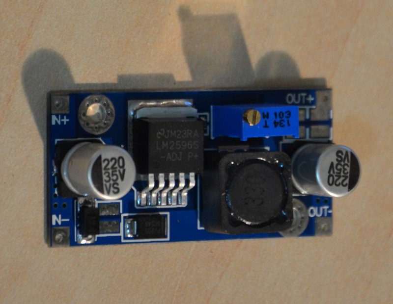
Ebay price 1.59 USD
2. USB outlet, I used a double, which was dropped from the old USB hub.
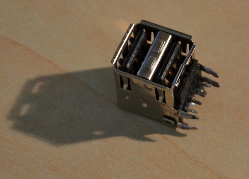
You can also use regular sockets from a USB extension cable.
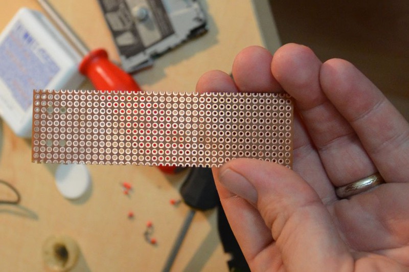
3. Development board. In order to solder a USB socket to something and assemble a simple charging circuit for Apple.
4. Resistors or resistance, as you like, and one LED. A total of 5 pieces, 75 kOhm, 43 kOhm, 2 with a nominal value of 50 kOhm and one for 70 ohm. In the first 4, Apple’s charging circuit is being built, I used 70 Ohm to limit the current on the LED.
5. Housing. I found in the bins of the homeland case from the flashlight Mag-Lite. In general, a black toothbrush case would ideally fit, but I could not find one.
6. Soldering iron, rosin, solder, wire cutters, drill and an hour of free time.
We collect exercises
1. First of all, I short-circuited the DATA + and DATA- pins on one of the sockets:
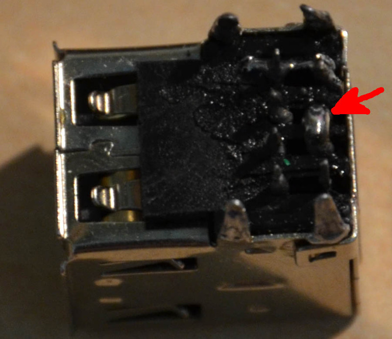
* I apologize for the harshness, got up early and the body wanted to sleep, and the brain continued the experiment.
This will be our outlet for non-apple gadgets.
2. We cut off the size of the mock-up board we need and mark and drill holes in it for the USB socket fixing legs, while at the same time checking that the contact feet coincide with the holes in the board.
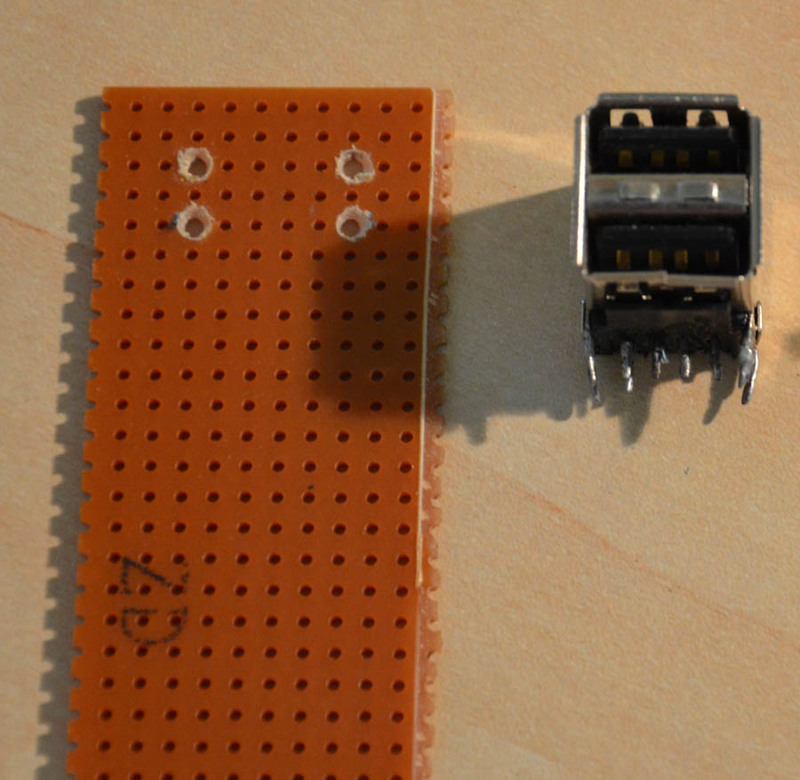
3. Insert the socket, fix and solder to the breadboard. Contacts + 5V of the first (1) and second (5) sockets are interlocked with each other, and we do the same with the GND contacts (4 and 8).
The photo is for explanation only, the contacts are already soldered on the breadboard
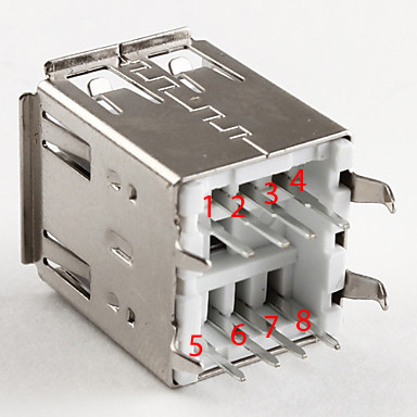
4. Unscramble the remaining two pins DATA + and DATA- with the following scheme:
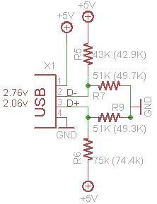
To observe the polarity, use the USB pinout:
I did this:
Do not forget to adjust the output voltage, using a screwdriver and a voltmeter, we set 5 - 5.1V.
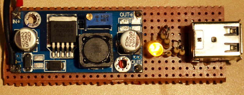
I also decided to add an indication to the USB power circuit, parallel to + 5V and GND soldered yellow ice with a 70 Ohm resistor to limit the current.
We kindly request to people with fine mental organization and other lovers of beauty: "Do not look at the following picture, because the soldering curve."
I'm brave!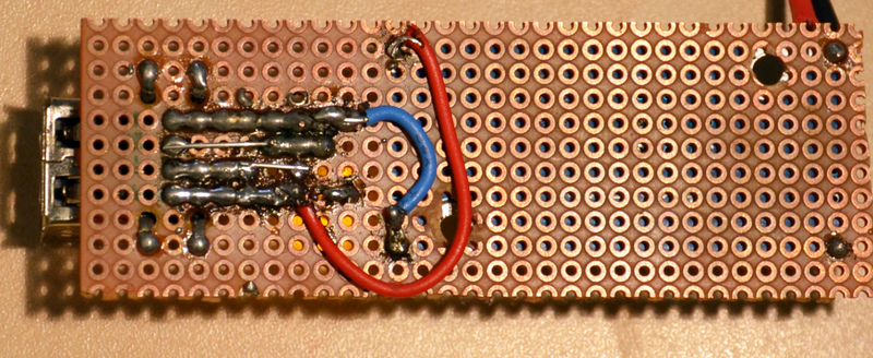
5. We fix a fee converter on our breadboard. I accomplished this with the help of the legs from all the same resistors, soldering them into the contact holes on the converter board and on the breadboard.
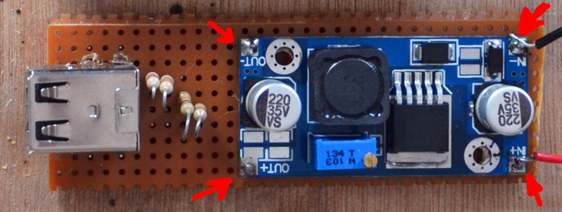
6. Solder the converter outputs to the corresponding inputs on the USB-socket. Observe the polarity!
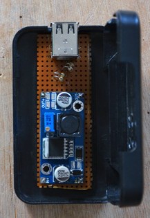
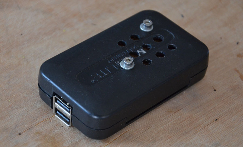
7. We take the case, mark it up and drill the holes for fastening our board, mark up and cut out the space for the USB socket and add holes for ventilation opposite the converter chip.
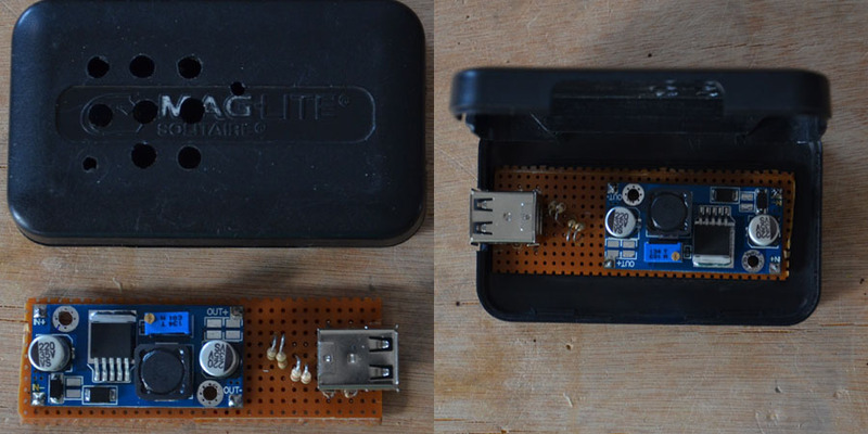
Fasten the breadboard to the case with bolts and get this box:
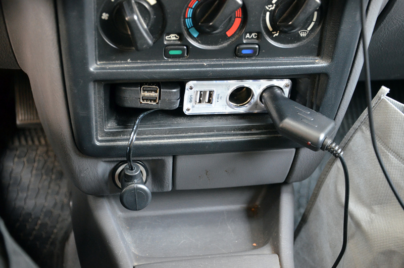
In the car, it looks like this:
Tests
Next, I decided to check whether my devices will actually assume that they are charging from their own charging. And at the same time measure and currents.
Power is provided by the PSU from an old 24V 3.3A printer.
I measured the current before going to USB.
Looking ahead, I say, all the devices I have have recognized charging.
I connected the number one USB socket (which is designed for different gadgets):
HTC Sensation, HTC Wildfire S, Nokia E72, Nexus 7, Samsung Galaxy ACE2.
For Sensation and Nexus 7, I checked the charging time, started with 1% and charged up to 100%.
The smartphone was charged in 1 hour 43 minutes (Anker's battery at 1900 mAh), I should note that it charges about 2 hours from standard charging.
The tablet also charged for 3 hours and 33 minutes, which is half an hour longer than charging from the network (Only one device was charging at a time).
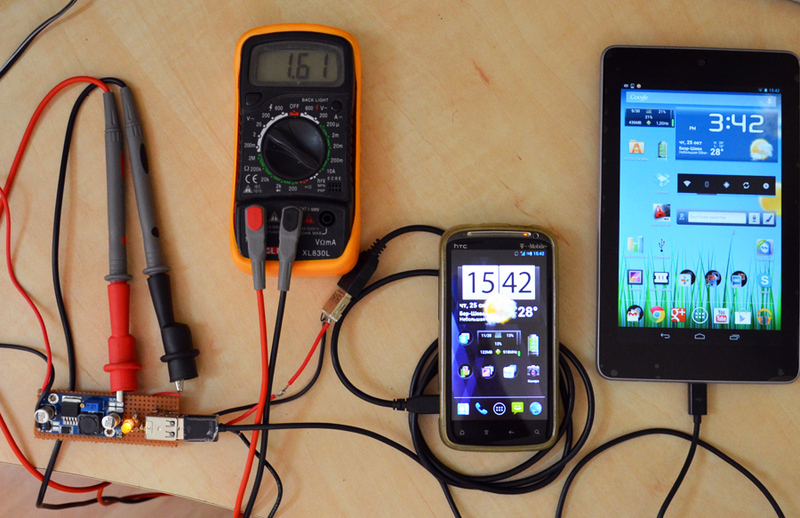
In order for both Android devices to take maximum charge, I had to solder a small adapter (which connected to apple USB), HTC Sensation is connected to it.
I connected to the USB socket number two: Ipod Nano, Ipod Touch 4G, Iphone 4S, Ipad 2. Because Nano is so funny to charge with such a thing - it took me a maximum of 200 mA, checked Touch 4g and iPad. Ipod charged 1 hour 17 minutes from zero to 100% (albeit with the iPad 2). Ipad 2 was charging 4 hours and 46 minutes (one).
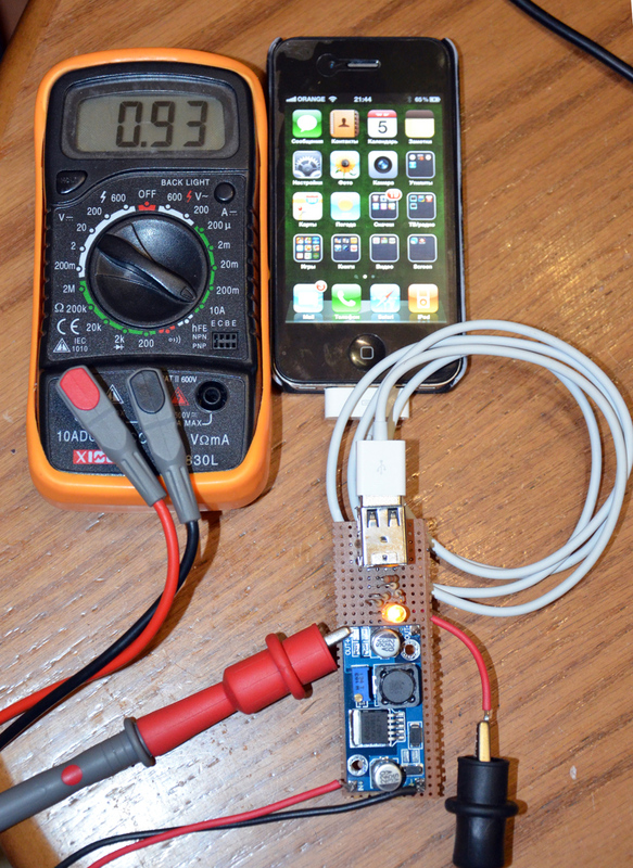
As you can see, the Iphone 4S gladly consumes its rated current.
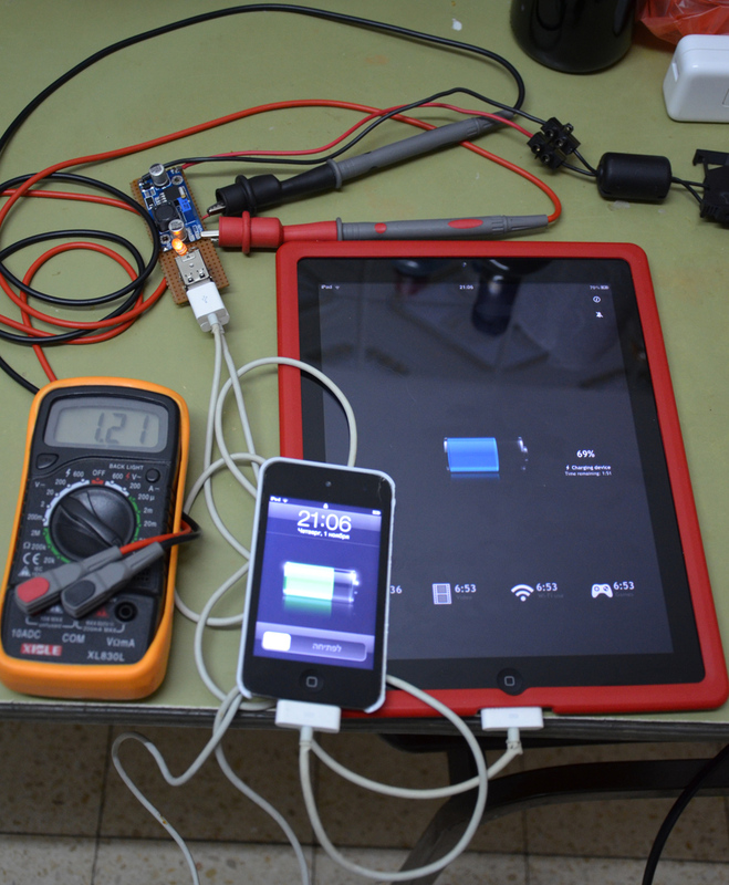
By the way, Ipad 2 surprised me, he absolutely did not shy away from the circuit with short-circuited date contacts and consumed absolutely the same currents as from the socket intended for it.
Charging process and conclusions
To begin, let me remind you that all devices that use lithium batteries have a charge controller available. It works as follows:
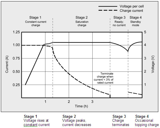
The graph is averaged and may vary for different devices.
As can be seen from the graph, at the beginning of the charging cycle, the controller allows you to charge the maximum permissible current for your device and gradually reduces the current. The charge level is determined by the voltage, so the controllers monitor the temperature and turn off charging at high values of the latter. Charge controllers can be located in the device itself, in the battery or in the charger (very rarely).
More information about charging lithium cells can be found here .
Actually here we come to the moment why this topic is called: “Attempt number one.” The fact is that the maximum that I managed to squeeze out of charge is: 1.77A

Well, the reason, in my opinion, is not the optimally chosen inductance coil, which in turn does not allow Buck - the converter to issue its maximum current. I thought of replacing it, but I don’t have an SMD soldering tool in the near future. This is not an error of the designers of the board with ebay, it is just a feature of this circuit since it is oriented to various incoming and outgoing voltages. Under such conditions it is simply impossible to issue the maximum current over the entire voltage range.
As a result, I got a device that can charge two smartphones at the same time or one tablet in the car in the time it is calculated.
In connection with the foregoing, it was decided to leave this charge as it is and assemble a new one, completely with your own hands, based on the more powerful LM2678 converter,
which in the future, will be able to “feed” two tablets and a smartphone at the same time (5A at the output). But more about that next time!
PS:
1. The text may contain punctuation, grammatical and semantic errors, please report them to the PM.
2. Thoughts, ideas, technical corrections and DD from more experienced comrades - on the contrary, are welcome in the comments.
3. I apologize for any technical inaccuracies, because until recently I was not engaged in electronics and circuit engineering.
Thank you for your attention, Good luck and inexhaustible optimism!
Source: https://habr.com/ru/post/155125/
All Articles