Weather station on STM32L-DISCOVERY
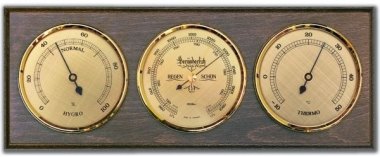
From childhood, he dreamed of a room thermometer, hygrometer and barometer (they did not pass the lessons of natural history and biology for nothing). Even a wall-mounted version was purchased with a Soviet-type switch instruments such as:
But he was mistakenly hung on the door and after some time, having become unusable, from constant shaking, he began to show the same value. Psychrometer frightened his appearance. Yes, and write down every day testimony - a silly idea. Mechanical systems were buried altogether with the arrival of controllers.
Long looked after various debug boards. On the advice of a friend, I bought a STM32L-Discovery debug board from ST, a detailed description here . It is tempting that this is an ARM on the core of the Cortex-M3. The heart of the board is STM32L152RBT6. There is also an on-board ST-Link programmer and debugger and a six-segment LCD display.

Post your own weather station , a thermometer on the SHT21 and the presence of STM32L-Discovery inspired the project.
')
Having a little accustomed to Keil, I downloaded instead of the example on board, another example is the Temperature project - and voila the thermometer is ready. The microcontroller can measure Vref. He also has his own chip temperature sensor.
Everything would be fine, but this sensor shows the crystal temperature, I decided to add a DS18B20 temperature sensor, and it would be nice to learn one-wire interface. It turned out that in order to add anything, the first thing to do is get rid of the standard LCD screen, with its 6 characters it occupies almost all free ports of the processor.
An old LCD screen assembled on Hitachi controllers lay in the bins of the homeland (8 lines of 25 characters each)

The above mentioned article mentioned the HIH3610 digital humidity sensor, but the capacitive humidity sensor HCH1000 and the barometric sensor HSF1000 were purchased.
So, we organized the tasks for connecting the equipment:
1. Connecting and programming the LCD screen;
2. Connect and receive data from RTL;
2. Connecting a DS18B20 digital temperature sensor and reading one-wire data from it;
3. Connecting a capacitive sensor HCH1000 and receiving data;
4. Connecting the HSF1000 piezoelectric sensor and receiving data;
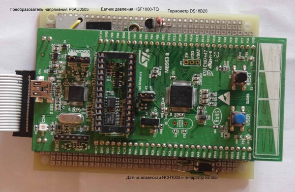
That such a device came out:
The copy I got in my hands turned out to be so old that there was no documentation from him. It had 4 HD44102CH chips and 2 HD44102 chips, and 4 discrete chips which I did not find a description of.
The reference manual on the HD44102 was found, and there were 8 legs of 4 microcircuits interconnected and mated to the connector - this was how D0-D7 was found, the power was found on discrete microcircuits. There were RW, E, CS, R / S signals. The HLM9301 LCD module was found in youtub very similar to my LCD, the Italian on the www.lcdstudio.com forum gave a pinout that coincided with the a priori I collected:
1 GND; 2 VCC;
3 contraste (generalmente terminal medio de potenciometro de 10k colocado entre vcc y gnd) 4 NC (no conectado);
5 NC; 6 CS1;
7 CS2; 8 CS3;
9 NC; 10 E;
11 R / W 12 R / S (DATA / INSTRUCTION)
13 D0; 14 D1;
15 D2; 16 D3
17 D4; 18 D5;
19 D6; 20 D7.
But when giving the commands, the matrix showed no signs of life.
After a long, no less than the previous, search on the Internet, it turned out that the old graphic screens needed negative voltage for brightness. A DC-DC P6AU0505 converter was turned on and a precision variable resistor 200kΩ was installed between the brightness and –5 outputs.
The teams from HD44102 came up. A library has been written to work with HLM9301. On the forums, the guys claimed that everything worked with Arduino immediately with the standard GLCD library.
The video shows the read data from the internal RTC and thermometer.
RTC initialization is as follows:
Problem: when reset, the RTC was also reset. The code snippet taken from the demo did something with the LSE - this was the reset of the RTC.
Reading data:
Then we got two new tasks “or”: turn on the ionistor in the power supply circuit of the microcircuit and, if the supply voltage drops, go into “sleep mode”, or attach an external RTC. I think to try both methods ...
Thanks to the articles Stm32 + 1-wire + DMA (continued) and Stm32 + 1-wire + DMA , the onewire.c library has been added, but for the STM32L152 processor port initialization looks a bit different:
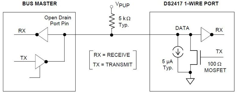
Connection diagram taken from datasheet:
With the help of the “Device Search” article , the ability to connect multiple devices to the one-wire bus was added. The resolution at DS18B20 when reading all 12 bits is 0.0625 degrees Celsius.
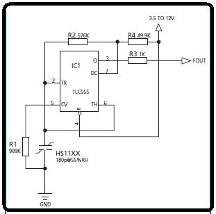
You can measure capacitance in different ways, the simplest method is to charge and monitor the voltage drop, considering the time to calculate the capacitance, or you can estimate the capacitance by AC resistance. Honeywell graciously provided a datasheet in which the sensor was the master value in the generator at 555. I used the last method and put together a simple generator:
It was not difficult to calculate the frequency. STM32L152 has several timers that can work in the mode of capturing the parameters of the PWM signal. Details here .
The difference was, as is the case with the one-wire port configuration:
Otherwise, all the text in the interrupt subtract the values of the counters, get the length of the period, multiplied by the coefficient is the capacity, from the capacity according to the graphs of the sensor went to humidity.
I connected the sensor to Vref, GND and to the input of the ADC. Experience has shown that the accuracy of a 12-bit ADC is not enough to evaluate the useful signal. Connecting the AD8555 instrumentation amplifier according to the standard scheme to the sensor gave its fruits. Gain 10 times was enough to raise the signal level to 0.7V.

Here is the main screen of the device
values in the rows:
1. date time from internal RTL;
2. duty cycle and period of the signal from the generator, as well as the number of one-wire devices found;
3. the capacity of the humidity sensor and humidity;
4. one-wire identifier;
5. temperature value;
6. voltage value;
7. crystal temperature value;
8. pressure value.
Project sources here
But he was mistakenly hung on the door and after some time, having become unusable, from constant shaking, he began to show the same value. Psychrometer frightened his appearance. Yes, and write down every day testimony - a silly idea. Mechanical systems were buried altogether with the arrival of controllers.
Long looked after various debug boards. On the advice of a friend, I bought a STM32L-Discovery debug board from ST, a detailed description here . It is tempting that this is an ARM on the core of the Cortex-M3. The heart of the board is STM32L152RBT6. There is also an on-board ST-Link programmer and debugger and a six-segment LCD display.
Post your own weather station , a thermometer on the SHT21 and the presence of STM32L-Discovery inspired the project.
')
Having a little accustomed to Keil, I downloaded instead of the example on board, another example is the Temperature project - and voila the thermometer is ready. The microcontroller can measure Vref. He also has his own chip temperature sensor.
Everything would be fine, but this sensor shows the crystal temperature, I decided to add a DS18B20 temperature sensor, and it would be nice to learn one-wire interface. It turned out that in order to add anything, the first thing to do is get rid of the standard LCD screen, with its 6 characters it occupies almost all free ports of the processor.
An old LCD screen assembled on Hitachi controllers lay in the bins of the homeland (8 lines of 25 characters each)
The above mentioned article mentioned the HIH3610 digital humidity sensor, but the capacitive humidity sensor HCH1000 and the barometric sensor HSF1000 were purchased.
So, we organized the tasks for connecting the equipment:
1. Connecting and programming the LCD screen;
2. Connect and receive data from RTL;
2. Connecting a DS18B20 digital temperature sensor and reading one-wire data from it;
3. Connecting a capacitive sensor HCH1000 and receiving data;
4. Connecting the HSF1000 piezoelectric sensor and receiving data;
That such a device came out:
Connecting and programming the LCD screen
The copy I got in my hands turned out to be so old that there was no documentation from him. It had 4 HD44102CH chips and 2 HD44102 chips, and 4 discrete chips which I did not find a description of.
The reference manual on the HD44102 was found, and there were 8 legs of 4 microcircuits interconnected and mated to the connector - this was how D0-D7 was found, the power was found on discrete microcircuits. There were RW, E, CS, R / S signals. The HLM9301 LCD module was found in youtub very similar to my LCD, the Italian on the www.lcdstudio.com forum gave a pinout that coincided with the a priori I collected:
1 GND; 2 VCC;
3 contraste (generalmente terminal medio de potenciometro de 10k colocado entre vcc y gnd) 4 NC (no conectado);
5 NC; 6 CS1;
7 CS2; 8 CS3;
9 NC; 10 E;
11 R / W 12 R / S (DATA / INSTRUCTION)
13 D0; 14 D1;
15 D2; 16 D3
17 D4; 18 D5;
19 D6; 20 D7.
But when giving the commands, the matrix showed no signs of life.
After a long, no less than the previous, search on the Internet, it turned out that the old graphic screens needed negative voltage for brightness. A DC-DC P6AU0505 converter was turned on and a precision variable resistor 200kΩ was installed between the brightness and –5 outputs.
The teams from HD44102 came up. A library has been written to work with HLM9301. On the forums, the guys claimed that everything worked with Arduino immediately with the standard GLCD library.
The video shows the read data from the internal RTC and thermometer.
Connect and retrieve data from RTL
RTC initialization is as follows:
RCC_APB2PeriphClockCmd(RCC_APB2Periph_ADC1 | RCC_APB2Periph_SYSCFG, ENABLE); PWR_RTCAccessCmd(ENABLE); RCC_LSEConfig(RCC_LSE_ON); //do not touch LSE to prevent RTC calendar reset while (RCC_GetFlagStatus(RCC_FLAG_LSERDY) == RESET) {} RCC_RTCCLKCmd(ENABLE); Problem: when reset, the RTC was also reset. The code snippet taken from the demo did something with the LSE - this was the reset of the RTC.
Reading data:
RTC_DateTypeDef RTCDateStr; RTC_TimeTypeDef RTCTimeStr; RTC_GetTime(RTC_Format_BIN, &RTCTimeStr); RTC_GetDate(RTC_Format_BIN, &RTCDateStr); sprintf(strDisp, "%02d/%02d/%02d %02d:%02d:%02d", RTCDateStr.RTC_Year, RTCDateStr.RTC_Month, RTCDateStr.RTC_Date, RTCTimeStr.RTC_Hours, RTCTimeStr.RTC_Minutes, RTCTimeStr.RTC_Seconds); Then we got two new tasks “or”: turn on the ionistor in the power supply circuit of the microcircuit and, if the supply voltage drops, go into “sleep mode”, or attach an external RTC. I think to try both methods ...
Connecting a digital temperature sensor DS18B20
Thanks to the articles Stm32 + 1-wire + DMA (continued) and Stm32 + 1-wire + DMA , the onewire.c library has been added, but for the STM32L152 processor port initialization looks a bit different:
GPIO_InitStructure.GPIO_Pin = GPIO_Pin_2; GPIO_InitStructure.GPIO_Mode = GPIO_Mode_AF; GPIO_InitStructure.GPIO_Speed = GPIO_Speed_40MHz; GPIO_InitStructure.GPIO_OType = GPIO_OType_PP; GPIO_InitStructure.GPIO_PuPd = GPIO_PuPd_UP; GPIO_Init(GPIOA, &GPIO_InitStructure); GPIO_PinAFConfig(GPIOA, GPIO_PinSource2, GPIO_AF_USART2); GPIO_InitStructure.GPIO_Pin = GPIO_Pin_3; GPIO_Init(GPIOA, &GPIO_InitStructure); GPIO_PinAFConfig(GPIOA, GPIO_PinSource3, GPIO_AF_USART2); Connection diagram taken from datasheet:
With the help of the “Device Search” article , the ability to connect multiple devices to the one-wire bus was added. The resolution at DS18B20 when reading all 12 bits is 0.0625 degrees Celsius.
Connecting a capacitive sensor HCH1000
You can measure capacitance in different ways, the simplest method is to charge and monitor the voltage drop, considering the time to calculate the capacitance, or you can estimate the capacitance by AC resistance. Honeywell graciously provided a datasheet in which the sensor was the master value in the generator at 555. I used the last method and put together a simple generator:
It was not difficult to calculate the frequency. STM32L152 has several timers that can work in the mode of capturing the parameters of the PWM signal. Details here .
The difference was, as is the case with the one-wire port configuration:
GPIO_InitStructure.GPIO_Pin = GPIO_Pin_1; GPIO_InitStructure.GPIO_Mode = GPIO_Mode_AF; GPIO_InitStructure.GPIO_OType = GPIO_OType_PP; GPIO_InitStructure.GPIO_PuPd = GPIO_PuPd_UP; GPIO_InitStructure.GPIO_Speed = GPIO_Speed_40MHz; GPIO_Init(GPIOA, &GPIO_InitStructure); GPIO_PinAFConfig(GPIOA, GPIO_PinSource1, GPIO_AF_TIM2); Otherwise, all the text in the interrupt subtract the values of the counters, get the length of the period, multiplied by the coefficient is the capacity, from the capacity according to the graphs of the sensor went to humidity.
Connection of the piezoelectric sensor HSF1000
I connected the sensor to Vref, GND and to the input of the ADC. Experience has shown that the accuracy of a 12-bit ADC is not enough to evaluate the useful signal. Connecting the AD8555 instrumentation amplifier according to the standard scheme to the sensor gave its fruits. Gain 10 times was enough to raise the signal level to 0.7V.
Here is the main screen of the device
values in the rows:
1. date time from internal RTL;
2. duty cycle and period of the signal from the generator, as well as the number of one-wire devices found;
3. the capacity of the humidity sensor and humidity;
4. one-wire identifier;
5. temperature value;
6. voltage value;
7. crystal temperature value;
8. pressure value.
Project sources here
Source: https://habr.com/ru/post/153395/
All Articles