DIY digital tachometer on AVR ATtiny2313, KR514ID2 and optocoupler
DIY digital tachometer on AVR ATtiny2313, KR514ID2 and optocoupler
Good day.
I am issuing for your consideration a simple digital tachometer circuit on the AVR ATtiny2313 , KR514ID2 , and an optocoupler designed by me.
Immediately make a reservation: there are many similar schemes on the Internet. Each implementation has its pros and cons. Perhaps someone will suit my option more.
I will begin, perhaps, with those. tasks.
Task : you need to make a digital tachometer to control the speed of the electric motor of the machine.
Introductory conditions : There is a ready reference disk for 20 holes from a laser printer. In the presence of a lot of optocouplers from broken printers. Average (working) speed 4 000-5 000 revolutions / minute. The accuracy of the displayed results should not exceed ± 100 revolutions.
Restriction : the power supply for the control unit is 36V (the tachometer will be installed in one case with the control unit - more on this below).
A small lyrical digression. This is my friend's machine. The machine is equipped with an electric motor PIK-8, which revolutions are controlled according to the scheme found on the Internet and modified. At the request of a friend, a simple tachometer was developed for the machine.
')
Initially, it was planned to use ATMega16 in the scheme, but having considered the conditions, it was decided to confine to ATtiny2313, operating from an internal (RC) generator at a frequency of 4 MHz.
The general scheme is as follows:
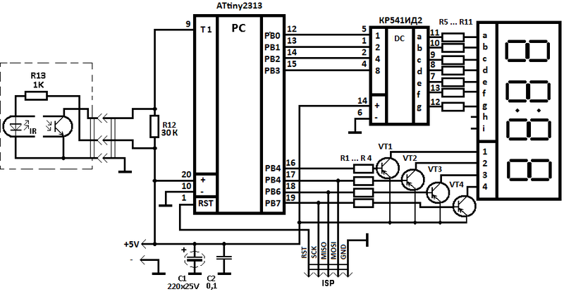
As you can see, nothing complicated. To convert a binary code into a seven-segment one, I used the decoder CR514ID2, this gives three pluses at once.
- Firstly, it saves space in the memory of ATtiny2313 by reducing the working code (since the procedure for programmatically converting binary to seven-segment code is absent in the firmware as unnecessary).
- Secondly: reducing the load on the outputs ATtiny2313, t. To. the LEDs “light up” the KR514ID2 (when displaying the number 8, the maximum consumption will be 20-30 mA (typical for one LED) * 7 = 140-210 mA, which is “much” for ATtini2313 with its full passport maximum (loaded) consumption of 200 mA).
- Thirdly, the number of “busy” legs of the microcontroller has been reduced, which gives us the opportunity in the future (if necessary) to modernize the circuit by adding new features.
The device is assembled on a breadboard. For this, the charge from the non-working microwave oven, which was lying in the bins, was dismantled. Digital LED indicator, key transistors (VT1-VT4) and limiting resistors (R1 - R12) were taken as a set and transferred to a new board. The entire device is assembled, with the necessary components, with smoke breaks for half an hour. I draw attention: the KR514ID2 chip has a plus power supply leg - 14, and a minus - 6 (marked on the diagram) . Instead of 5142, you can use any other binary code decoder in the seven-segment with 5V power supply. I took what was at hand.
Conclusions "h" and "i" of the digital LED indicator are responsible for two points in the center between the numbers, not connected as unnecessary.
After assembly and firmware, provided there are no installation errors, the device starts working immediately after switching on and does not need to be configured.
If it is necessary to make changes to the tachometer firmware, an ISP connector is provided on the board.
In the diagram, the pull-up resistor R12, with a nominal value of 30 kOhm, is chosen empirically for a specific optocoupler. As practice shows, it may differ for different optocouplers, but the average value of 30 kΩ should ensure stable operation for most printer optocouplers. According to the documentation for ATtiny2313, the size of the internal pull-up resistor is from 20 to 50 kΩ depending on the implementation of a particular batch of microcontrollers (page 177 of the passport to ATtiny2313), which is not quite suitable. If anyone wants to repeat the circuit, it can start with an internal pull-up resistor, maybe you will work for your optocouplers and your MK. It didn't work for me.
It looks like a typical optocoupler from the printer.
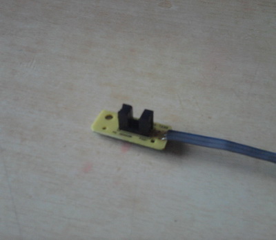
The optocoupler LED is powered through a 1K limiting resistor, which I placed directly on the board with the optocoupler.
To filter the voltage ripple on the circuit, two capacitors, electrolytic at 220 microfarads x 25V (which was at hand) and ceramic at 0.1 microfarads, (the general circuit for switching on the microcontroller is taken from the ATtiny2313 passport).
To protect against dust and dirt, the tachometer board is covered with a thick layer of automotive lacquer.
Replacing components.
You can use any LED indicator on four digits, or two doubles, or four single. At the worst, collect the indicator on separate LEDs.
Instead of KP514ID2, KP514ID1 (which contains current-limiting resistors inside), either 564ID5, K155PP5, K155ID9 (when the legs of one segment are connected in parallel), or any other binary to seven-segment converter (with corresponding changes in the connection of the output circuits) can be used.
If the installation is properly transferred to the ATMega8 / ATMega16 MK, this firmware will work as on ATtiny2313, but you need to tweak the code (change the names of the constants) and recompile. For other AVR MK comparison was not conducted.
VT1-VT4 transistors - any low-current, operating in the key mode.
The principle of operation is based on counting the number of pulses received from the optocoupler in one second and recalculating them to display the number of revolutions per minute. For this, an internal Timer / Counter1 counter operating in the pulse counting mode at the input of T1 (PD5 pin of 9 MK pin) was used. For ensuring stability of work, the mode of a software chatter suppression is included. The countdown of seconds is performed by Timer / Counter0 plus one variable.
The calculation of revolutions , on what I would like to dwell upon, occurs according to the following formula:
M = (N / 20) *60,where M is the calculated revolutions per minute (60 seconds), N is the number of pulses from the optocoupler per second, 20 is the number of holes in the reference disk.
Total, simplifying the formula we get:
M = N*3.But! ATtiny2313 microcontroller is missing a hardware multiplication function. Therefore, summation with offset was applied.
For those who do not know the essence of the method:
The number 3 can be expanded as
3 = 2 + 1 = 2 1 + 2 0 .
If we take our number N, move it to the left by 1 byte and add one more N shifted to the left by 0 byte - we get our number N multiplied by 3.
In the firmware, the code on AVR ASM for a double-byte multiply operation is as follows:
Mul2bytes3:CLR LoCalcByte //CLR HiCalcBytemov LoCalcByte,LoInByte // Timer/Counter1mov HiCalcByte,HiInByteCLC //ROL LoCalcByte //ROL HiCalcByteCLCADD LoCalcByte,LoInByte //ADC HiCalcByte,HiInByteretVerification and accuracy measurement was carried out as follows. A cardboard disc with twenty holes was glued to the fan of the computer cooler. The speed of the cooler was monitored via the motherboard BIOS and compared with the tachometer readings. The deviation was about 20 revolutions at a frequency of 3200 revolutions / minute, which is 0.6%.
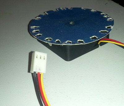
It is possible that the real discrepancy is less than 20 revolutions, since measurements of the motherboard are rounded within 5 revolutions (according to personal observations for one particular board).
The upper limit of measurement is 9,999 revolutions per minute. The lower limit of measurement, theoretically from ± 10 revolutions, but in practice was not measured (one pulse from the optocoupler per second gives 3 revolutions per minute, which, given the error, should theoretically correctly measure the speed from 4 revolutions per minute and higher, but in practice figure must be overestimated at least twice).
Separately focus on the issue of nutrition.
The whole circuit is powered from a 5V source, the estimated consumption of the entire device does not exceed 300 mA. But, according to the terms of the TZ, the tachometer should be located inside the engine speed control unit, and a constant voltage of 36V is supplied to the unit from LATR, in order not to pull a separate power wire, LM317 is installed inside the unit in passport mode, in power down mode to 5V ( limiting resistor and zener diode for protection against accidental overvoltage). It would be more logical to use a PWM controller in the step-down mode of the converter, similar to MS34063, but in our city it is problematic to buy such things, so they used what they could find.
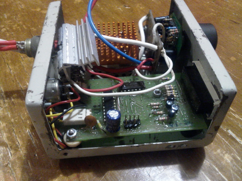
Photos of the tachometer board and the finished device.

More photos

Unfortunately, now there is no opportunity to photograph on the machine.
After the layout of the boards and the first test assembly, the box with the device went for painting.
The source code, on AVR ASM, the AVR Studio4 project files and the compiled .HEX file are located here: http://djkiridza.org.ua/ldd/taho-v029.zip .
The mirror is here: http://fileobmen.org.ua/DJ_Kiridza/taho-v029.zip
In the event that your tachometer did not start immediately after switching on, with a deliberately correct installation:
1) Check the operation of the microcontroller, make sure that it works from the internal generator. If the circuit is assembled correctly, four zeros should be displayed on the dial.
2) Check the level of the pulses from the optocouplers, if necessary, select the value of resistor R12 or replace the wiring diagram of the optocouplers. It is possible to reverse the connection of the optotransistor with a pull-up to the negative, with the internal pull-up resistor MK turned on or not. It is also possible to use a transistor in a key (inverting) mode of operation.
PS at the request of the customer a tachometer displays not one zero, but four in the absence of pulses from an optocoupler.
PPS The tachometer was very sensitive to engine speed. Minor voltage ripples cause speed deviation, which is immediately displayed on the tachometer screen. In the future, I plan to do the processing for rounding up the displayed results within ± 50 revolutions, if required by the customer.
Source: https://habr.com/ru/post/153125/
All Articles