Simple wifi bot for monitoring premises or "kitchen" robotics
Introduction.
Today, each of us has a dedicated line at home with a very “thick” channel. Also, most have a wifi router, and again, most of us do not care about turning it off when we leave home. And really why? The wifi security protocols are very reliable, the consumption of the router is negligible. Hence your home often or always on-line. But what does this give us? Torentokachalki, personal various servers, etc.
Particularly advanced of us have a smart home with a variety of "buns" and remote monitoring via the Internet. This is the right, but expensive solution. But all this makes sense to install only in their housing. In the case of removable this is absurd.
Nevertheless, exacerbations of paranoia, hyper-responsibility or similar factors (recall the classic situation - “Did I turn off the iron?”) Create certain discomfort for us when we leave our home. Especially for a long time. The question arises - how is it that the apartment is on-line all the time, and I see nothing and do not control. Strange.
')
The most budget solution to put questions just webcam. But one will not be enough, and a developed network of video surveillance is already a serious infrastructure and is not very cheap. Different options were considered and all the pros and cons were weighed. It turned out that the easiest way is to take one webcam, but attach wheels (or tracks) to it.
I am well aware that in this place the opinions of the readers will be divided into two large groups. The first one will state that there are similar projects of the sea, including here, and the second group will argue that in order to implement this, you need to be friends with a soldering iron.
This is how we approached the main goal of this material - how to realize this project as cheaply as possible and at the level accessible to many without immersion in the jungle of electronics.
Looking ahead to the front, I can say that the budget is minimal from $ 70 and to the limits of common sense. And it strongly depends on how accessible the components are and how much the individual is hoarding. This price tag was formed in Donetsk (Ukraine), a city, though progressive, but where to get certain things is still a problem.

Components.
All components of our wifi bot were selected based on the price / availability relationship. Finished expensive plastmasski for lovers of refined Arduino-buildings were swept away immediately. Otherwise, the budget would be equal to half the budget of the Lunokhod.
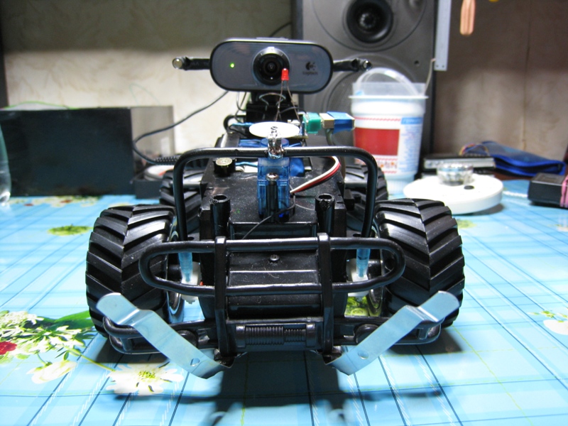
1. Chassis. Everything is simple here - we take the first “jeep” on the radio control (we will throw it away, therefore, it can be broken). There, as a rule, there is already a main engine (which pushes forward) and a rotary engine on the front “bridge”. Feel free to rip out the circuit RU (radio control) leaving only the wires to the engines and the wires from the compartment with batteries. For general development, it is possible to poke a battery into the motors and see where they spin at a specific polarity. This is how our cart will be moved.

Fig. 1 Chassis.
2. Brains. A device for broadcasting video stream and commands to our chassis. We need a device with wifi and a port to control the chassis. And since the raspberries (Raspberry Pi) are still available, not all will dwell on routers. They are shaped like this because there is Wifi, USB and the possibility of customization thanks to custom firmware. There were a lot of mocking D-link DIR-320, which he didn’t work with, but it’s not about him. It's time for him to retire. Progress does not stand still and now the function of "pensioner" on your shoulders can take the baby TP-LINK TL-MR3020, although it is not a fact that when you read it there will be a better option. The advantages of this model are primarily in size, and secondly it is more nimble. You also need to mention that you don’t have to cut the firmware for a long time and tediously, everything is already done right here at roboforum.ru/wiki/OR-WRT Many thanks to the guys with roboforum.ru for their huge contribution to home robotics. Therefore, all you have to do is flash the router and configure it a little for your specific conditions.

Fig. 2 TP-LINK TL-MR3020 router.
3. All-seeing eye. The webcam does not fit any, but this thorny let the choice has already been passed more than once. First of all, it should support UVC (USB Video Class) here www.ideasonboard.org/uvc there is a list. And secondly, it is good if she herself will compress the flow. The best is the Logitech Webcam C100, cheap and high quality. With the camera itself, you do not need to do anything, just install and connect to the USB router.

Fig. 3 Logitech Webcam C100
4. Driver control engine L293D. This is a 16 foot circuit. It does the following - if a voltage is applied to one input, then the motor turns in one direction, and if the second, then the other. The scheme supports just two motors. If you do not use it, you will have to bother with H-bridges, but I promised you not to ship with electronics. It costs a penny, and takes a headache decently.

Fig. 4 L293D motor control driver.
5. Microcontroller. You can use any that you have already mastered. The main thing is that he could take a couple of bytes through the UART and, depending on them, set 0 or 1 on the corresponding legs. I used the Arduino Mini Pro Chinese spill (please do not kick). Just for beginners this is the easiest.
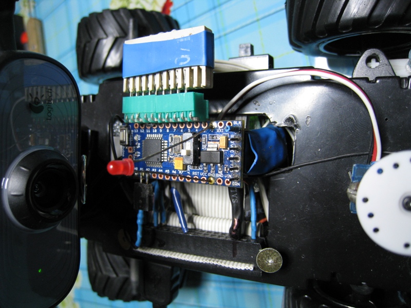
Figure 5. Microcontroller.
6. And the last - batteries. Many puzzled over the food and came to the conclusion that the easiest way to take four AA NiMh batteries. They reach 2500mAh capacity, are cheap and not afraid of overcharging. The latter is important to us because our bot must be able to recharge as there may simply be no one to charge it. The easiest way to do this is by connecting the battery directly to a power supply unit with the required voltage (6.4V) and which can provide a current equal to the consumption of the entire cart + another 50-100 mA for unhurriedly charging the battery. Thus, the cart will eat the current from the power supply unit, and the excess will “stick” into the battery. And no charge schemes are applied here! Yes, experienced electronics engineers have already sharpened their blades, but all this has been working for several months now without visible damage. The main thing is to find the right power supply. The current can be limited by a resistor. I also put a diode and got rid of the likely short circuit or pereplyusovki (if some Schumacher stuck in charge at the top of his feet). This is possible because of the design features, for example, you can simply rest your contacts on an iron door. Here peugeot-citroen.net/viewtopic.php?f=11&t=7332&p=104602 people did an exhaustive battery test for which special thanks to him.
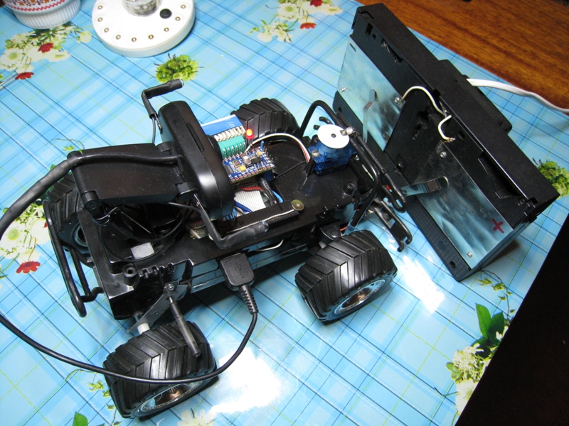
Fig. 6. Charging.
Assembly.
Batteries are mounted on the chassis and, for ease of installation, we make two long tires of tin that run along the chassis. (The tin from coffee cans is simply delightfully soldered.) To one we connect the “+” batteries through a toggle switch, which will de-energize the entire structure. Minus naturally connect to the second bus. Thus, all consumers can easily be soldered to the tires and not to arrange the orgy of wired connections. We solder elastic contacts to these tires in order to “rest against” charging.
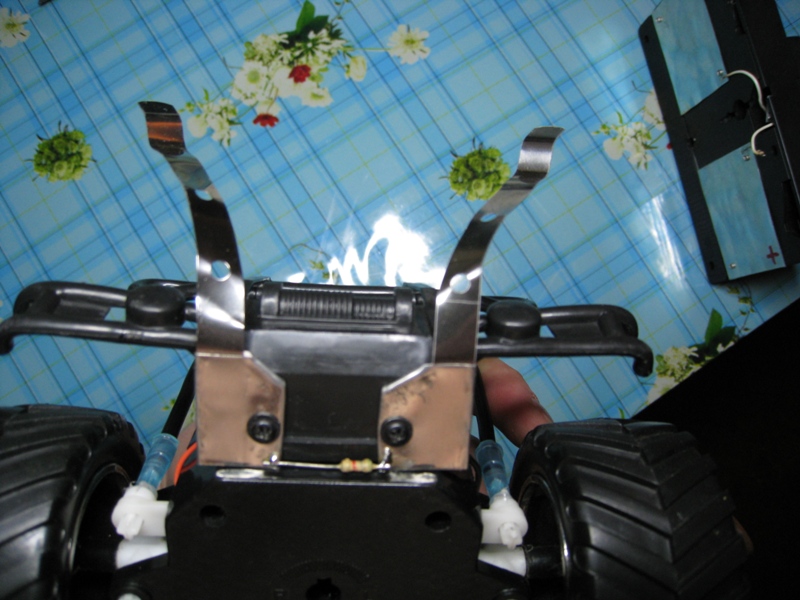
Fig. 7 Contacts for recharging.
Next, finish the router. We need to bring its internal UART out and make it so easy to connect a microcontroller there. I do not advise soldering tightly because you will program the microcontroller several times until you are satisfied with the result. It is necessary to connect this way: ground to ground, plus power to the positive, RX to TX and TX to RX. There is a pinout here wiki.openwrt.org/toh/tp-link/tl-mr3020 Next, fill in the OR-WRT firmware there, a detailed instruction is on the link to the wiki above, and configure it for your network. With the router done.
Fig. 8 Connection arduiny to the router.
Now we install the engine driver. Four legs to plus and 4 to minus and 4 more wires that are already soldered to the legs of the microcontroller ("RA0", "RA1", "RA2", "RA3"), and our engines to the remaining ones.
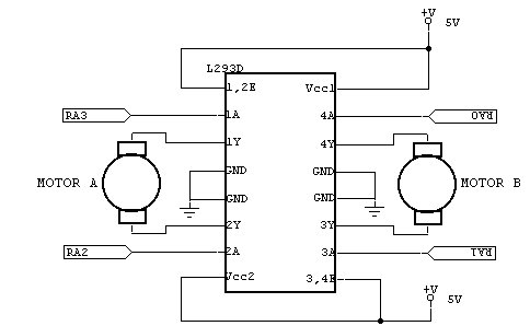
Fig. 9 Connection L293D.
It will work as follows if the microcontroller sets a high level, for example, on the leg to which the RA0 wire is soldered, motor No. 1 turns for example to the left, and if RA1 then to the right. Anticipating the question of what will happen if you install two units - nothing terrible will happen, the motor will turn in both directions at the same time. Joke. The engine will not spin. In the case of the N-bridge, this would be a short circuit, but our scheme is not afraid of this, it is stupid.
The microcontroller should, in a continuous loop, simply set the high level on the legs in accordance with the received byte. And that's all.
Here is the program for the Arduino Mini Pro microcontroller.
HomeBot1_min.pde
For its firmware, you need an ordinary UART adapter for a computer (not to be confused with RS232, this is the same but other voltages here), I use an old data cable from Siemens phones. Pin assignment is the same as when connected to the router, but we need another DTR pin from the RS232 connector, it connects to the “GREEN” pin on the microcontroller and when it starts the firmware is set to “0”, thanks to which the controller understands that it will be flashed right now. If you don’t get this contact from where you can just click on the Reset of the MC itself, I didn’t manage it, but there are live witnesses on the Internet.
The main thing is that the pins in the program coincided with the pins physically. If the motor does not turn or does not turn there, then just check the soldering, most likely it was mixed up. You can test it all very simply - after the firmware, do not disconnect the MC from the computer and simply send the necessary bytes to the corresponding port.
The very process of firmware is simple to disgrace. Open the sketch in the Arduino IDE, select the appropriate port and the version of the MK board in the menu. Click the Upload button and that's it. I will not dwell on this in more detail because it is full of articles on the topic of Arduino.
So at this stage we already have a chassis which is turned over by motors on orders from the MK which? in turn? receives commands on the UART. B we have a router that is flashed and configured to connect to the home network via wifi.
Now we need to slightly change the web interface so that the commands from it go straight to the internal UART of the router. Well, from it, respectively, in MK.
I did not bother and assigned the well-known buttons “A”, ”S”, ”D”, ”W” to control all of us, for example, if for example MK receives a byte “W” (0x57), it will install a unit on the foot to which the wire is soldered forward motion, etc.
Required file:
index.html
serial.cgi
Or all together
And a set of different versions of sketches, including the latest version with the serv.
There is changed only the fact that Java scripts that process button presses in the web interface now send “A”, ”S”, ”D”, ”W” depending on the button pressed. And the script itself which is engaged in sending is redirected to the internal UART of the router. Files need to replace the original files in the directory WWW.
The easiest way to do this is with the great winSCP program winscp.net/eng/docs/lang : ru on SSH.
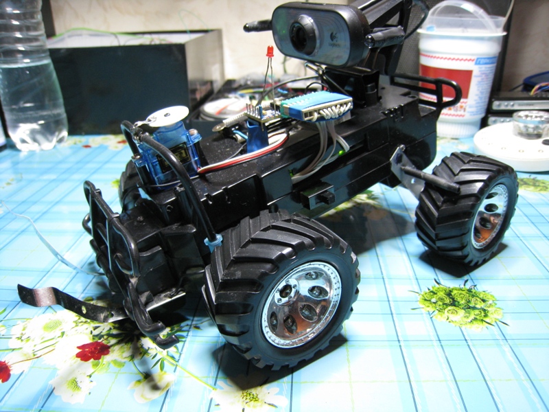
That's probably all. Having received a wifi bot, you can modify it at your discretion. Add different equipment. For example, replace the rotary motor with a servo. This will help keep the wheels turned without energy, but you can do without it.

Fig. 10 Servo Drive.
Charging is done and the usual transformer and rectifier. The old videotape is used as a frame, and the contacts are made of “coffee tin”. All that needs to be done is to steer and rest with the contacts in charge. Even when recharging, excess will go through the heat.
I understand that I still could not cover everything, and if there are enough questions I can make an extended article.
Finally, a little video.
Source: https://habr.com/ru/post/153017/
All Articles