IR remote for PC and sockets. Part 2
Part 1
Yesterday I explained how to build an Arduino USB-IRPC. What for? To show how to quickly assemble the layout and the complexity of the particular is not here.
Today we will do everything as it should be. From the very beginning - from the circuit diagram, PCB, LUT. A piece of foiled fiberglass converts with a handful of parts into a finished device. Of course with the case, we want it neatly, right?
Here is our goal:

" USB-IRPC Bare Front "

" USB-IRPC Finished "
So, we start with the concept. The diagram will only have USB-IRPC itself, since the module of sockets with a relay and the IR receiver with LED is “peripherals” and we will use it without changes.
I used DipTrace to draw a circuit and a circuit board for the following reasons:
It has a significant drawback - not a very rich library of elements, and also not the most convenient search through it. But editing the elements is not too difficult. In general, for now this is the least awkward program for me :)
Here is the scheme itself (see the full-size version better by clicking on the link and opening it in its original size):

USB-IRPC Scheme
In the center we have U1 - I used the Atmega168PA-AU, but Atmega88 and Atmega328P will do. The size of the firmware is just slightly over 4 kb.
The operation of the microcontroller (MK) at a frequency of 16 MHz provide capacitors C4 and C5 with quartz X1.
C2 - just a blocking capacitor, slightly smoothes the pulsations in the power circuit.
A block of R3 and U2 is used to "push" the power button of the PC.
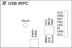
J1 - connector for connecting to the motherboard parallel to the power button.
S1 - Reset button. May be useful when debugging.
J5 and J6 - ISP6 connector for in-circuit programming (firmware).
J2 - connector for connecting the socket module with a relay.
J3 - connector for IR receiver module with LED.
D1 - the LED connected via the current limiting resistor R1 duplicates the remote LED on the board. It is useful for debugging, after assembly it is not visible inside the box, so it is not necessary to solder it. R4 - Resistor for remote LED on the receiver module.
J4 - USB Mini-B connector.
D2 and D3 - 3.6V zener diodes.
R5, R6, R7 - resistors to ensure the operation of V-USB.
That's the whole scheme.
At the end of the article links to download it in the format .sch (DipTrace)
It was more difficult to dissolve the PCB. I have this first experience and so it was not possible to dissolve one of the conductors in one layer, I had to leave the jumper. In addition, I forgot that the plugs on the board will be installed on the other side, and then I had to make a separate plug for the programmer. I, too, mistakenly placed the opto-couple on the wrong side, but this did not stop soldering it. I corrected all this in the version of the PCB that I posted for download. So your board will be slightly different from the one on my photos. For the better :)
In the course of sealing elements, I found that pouring copper too close to the tracks adds inconvenience and changed the fill, getting rid of the islands and making indents from the tracks wider.
Here's what happened:
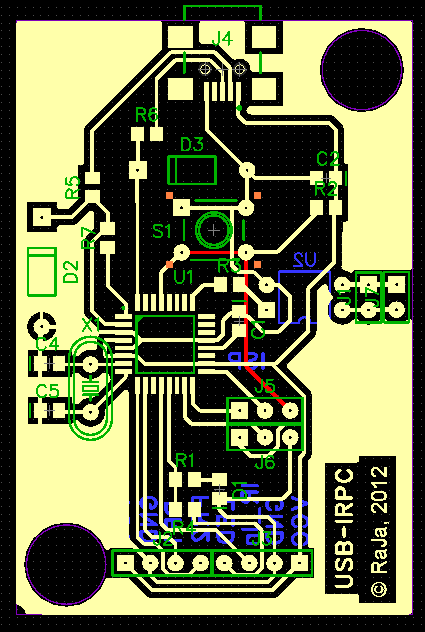
The red carpet is a jumper that could not be diluted.
A nice bonus DipTrace - the ability to see how the PCB will look. Unfortunately, the library has far from all the elements, but the overall result is still much more visual than in a flat form:
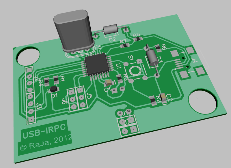
It can be seen that on the board I added connector J7 - just another pair of pins, connected in parallel with J1, in order to connect the power button connector from the PC case.
Ok, the circuit and the sample of the printed circuit board are ready, we buy the parts and produce them.
U1 - Atmega168PA-AU - in the TQFP-32 package - from 64 rubles (in icdarom, the minimum order is 1500r, delivery is 200), you can buy each piece for 130 rubles free. Atmega88PA-AU or Atmega328P-AU will do.
Lead Elements:
U2 - PC817, PDIP4 package
S1 - DTS-61 Clock button 6x6x4.3.
D2, D3 - 3.6V zener diodes
J2, J3 - PBS-4
J5, J6 - PBS-3
J1, J7 - PBS-2
')
SMD elements of size 0805
R1, R4 - 390 Ohm
R5, R6 - 68 Ohm
R7 - 2.2 kΩ
D1 - LED (any color, I have orange)
J4 - USB miniB connector
C1, C2 - 0.1 μF ceramic capacitors.
C4, C5 - 22 pF ceramic capacitors
X1- 16 MHz quartz
R3 is 100 ohms.
R2 - 10 kΩ
Lead-outs are bought on the radio market - approximately 50 rubles.
I bought the SMD elements at once for $ 9.85 - there are 40 pieces of each resistor and 30 capacitors each.
I took the box in icdarom for 40p, but it is also found in other stores of BOX-KA08 of different colors, around 65 rubles.
It even happens transparent:

I will not teach you how to make boards with LUT - DiHALT described everything simply and clearly . By the way, congratulate him on the day of jam. :)
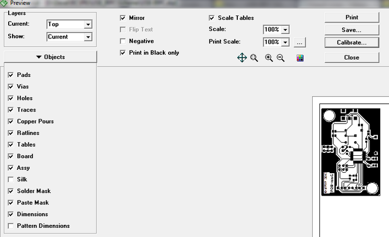
I’ll dwell only on points specific to DipTrace. When printing, do not forget to mirror and turn off the printing of the contours of the components:
You can do without DipTrace. I exported to a PNG file, take FastStone Viewer and print it like this:
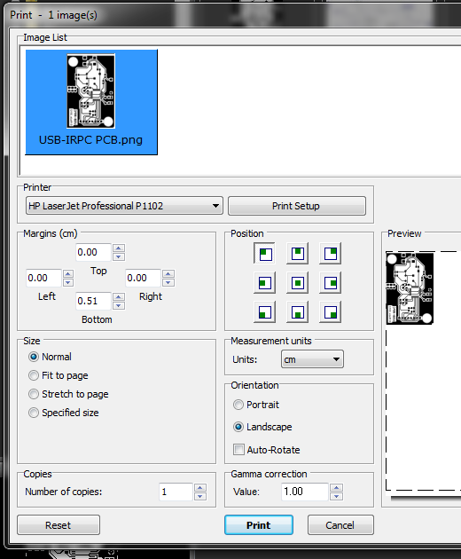
Print quality to maximum, savings off, resolution to maximum.
PNG prepared in 600 ppi.
Then everything is as usual: we translate, we poison, we wash the toner, we cut it out, we tinker, we drill:

" USB-IRPC "
My paper was dull and the toner rolled a little around the edges - it might not have been ironed properly, but there was nothing important there, only aesthetics suffered and that lightly.
Seal the components and label:
" USB-IRPC Bare Front "

" USB-IRPC Bare Back "
Please note that I have the PC817 on the wrong side and the rows of the ISP comb are in reverse order - this is my mistake, everything on your board will be correct.
Due to the fact that the mask in its version did not very well, when sealing elements, solder flows appeared, which are very difficult to remove at all. This moment I also took into account and corrected in the final version of the PCB layout. But I didn’t redo the board - it works well, it just doesn't look very good, unfortunately. The first pancake is always lumpy. But this time it was possible to make a more accurate trial.
I advise you to print a color image with inscriptions of elements on a 1: 1 scale (USB-IRPC_pcb.jpg) and use it as a cheat sheet when sealing elements and drilling holes.
Needle file carefully cut out the holes in the box. The outlines of the holes are marked on the body with a marker or pencil, cutting them with a stationery knife in the paper template and putting the template on the body. From the side, we saw through the slot for the miniUSB connector. We insert the board and try on:

" USB-IRPC "
If you do not plan on modifying the firmware, then it is not necessary to cut the holes for the ISP - the pins do not rest on the cover.
Then we print and paste the label. In the archive you will find the version of the sticker with and without ISP. depending on whether you cut holes under them or not. (I drilled the hole for Reset, but I didn’t cut through the sticker, it can be punctured with a toothpick if necessary, but it’s not useful yet).
Everything, the hardware is ready.

" USB-IRPC Size "
I simply poured the infrared module with hot melt and attached it to the monitor leg with double sided tape.

" USB-IRPC IR-Led module "
I do not like bright light at home, and under normal lighting it is almost imperceptible - the size of 1x3 cm.
The firmware is written in C in Code :: Blocks IDE. Compiler - AVR GCC from AVR Toolchain kit
I will explain the main points here so that you can understand the project code. Sources are on the project page, links at the end of the article.
I wrote a simulation of the functions DigitalRead and DigitalWrite, because I take some of the libraries from Arduino and, in order not to rewrite, just slip them into my version of the Wiring functions they call.
ir.h is an interface with an IR receiver. Shamelessly adapted example that came with a Chinese set of experiments with IR remote control. Almost unchanged.
usb_comm.h - defines command codes for exchange with a PC and the data structure in which they are transmitted.
USB pinstate bits - numbers of control bits of the relay and the LED in the package.
IRPC internal functions:
fRelay1Switch - toggle relay 1
fRelay2Switch - switch relay 2
fPCPwrSwitch - press the PC power button
irpcdata_t is the package structure that the device and the PC exchange.
Exchange takes place at the request of the PC.
cmd - command code (for example, cmdGetIRPCState)
data [] is an array of data of 4 bytes. Each team interprets it in its own way.
irrc.h - matching button codes with names, just for convenience. I recorded for my remotes. Like that:
In the usbconfig.h file, the V-USB library settings. I scooped information from this article .
If you do not understand the USB protocol, then you can not touch anything there.
Based program main.c
We define the SetPinState macro, which installs the outputs to the desired position and sets the corresponding state of the bits of this output in the pinStates variable.
We also determine the pins to which the peripherals are connected and the number of button correspondences to internal functions that we can store (MaxBtnMapings).
Variables (comments in the source did for myself, so they are mostly in clumsy English in the file :)
Received commands from the PC are stored in pcdata, sent - in pdata.
Main loop
We adjust pins to which relays and an LED are connected as exits.
We clear the correspondences of the buttons to the internal functions - is there any garbage in the memory when it is turned on?
Load the byte of the relay states and the LED - pinStates and set them to the appropriate state in the loadStateFromEEPROM () function.
Disable interrupts, disconnect from the PC, pause and let us detect. Then enable interrupts.
Prepare a timer to work with the IR receiver.
We start the data processing cycle from the IR receiver and PC:
Everything is simple:
When the PC wants to send us a packet, the usbFunctionWrite function is called when it requests a data packet — the usbFunctionRead function.
Let's sort them out:
First we fill in the pdata structure - if we were asked for the state of the device (cmdGetIRPCState), write the pinStates and the code of the pressed console button
If you have requested one of the corresponding buttons for internal functions, we give it by taking the function number from the first byte of the packet sent by the PC (pcdata.data [0])
If the command is not recognized, we simply give the pdata structure - when processing commands, the results are written into it.
Then we write our packet byte-wise by the pointer given in the data parameter.
It is even simpler here - we simply rewrite the packet with data in pcdata, without understanding what's what, processUSBcmd () processing will be performed, and we need to return control as quickly as possible - the function causes an interrupt.
And here, actually, it is:
Depending on the command received (its code in the pcdata.cmd field) we parse the pcdata.data package
everything is pretty transparent here, I think.
Having executed the command, we reset the cmdReceived flag.
In the process_IR () function we collect the 16-bit code of the button:
If the code is not equal to 0, then something was pressed, save for transferring the PC and set the flag to light the LED - show that we saw the button pressed.
Then I process the codes for the buttons on my remote control:
On the "Power" button, I press the PC power button until the remote control button is released.
Two other buttons switch the status of the relay.
Then we check the array of assigned correspondences of button codes to internal functions — this is for use with other consoles, correspondences are set with the PC by cmdSetIRBtnMapping commands — one command per button. We have seen the processing of this command above in processUSBcmd ()
In general, the main thing is to have time to quickly process interruptions and periodically poll the IR receiver and call usbPoll, otherwise the PC will lose us - “USB device not recognized”.
The version is designated as alpha for good reason - there are several pieces, as you have noticed, where the binding to a specific console has not been commented out yet, because the setting of the mapping of buttons and functions from the PC has not yet been written, it did not. Well, sometimes it happens that the device stops receiving commands from the PC, although it is visible in the system and responds to the buttons on the remote. I suspect that this is due to the long duration of the survey of the IR receiver, this should be optimized. However, it happens rarely and does not cause any inconvenience.
Now go to the program for the PC.
I will focus on the key points so that you can understand the source code.
Let me show you with an example plugin for MKey - it's easier to figure it out.
The plugin is written in Delphi7 because it turned out that MKey does not support unicode, and in Delphi 2010 with ANSI you need to mess around further.
From additional libraries only JVCL is used.
The main work is done in the uHID.pas module
It defines the same command constants as in the device, I will not duplicate them.
The same record describing the package, with one addition - the reportID - we do not support it and there is always 0 there, but in general there may not be only one device. We just lack one.
Additional constants only id devices - Vendor ID (Vid), Product ID (Pid) and DeviceName. By Vid and Pid, we will search our connected HID devices.
All functions of communication with the device are collected in the classroom.
The Dev field is a pointer to the device class, we get it when it is successfully connected to the device (Connect).
when disconnected (Disconnect) it is set to nil.
The methods are very simple, so I’ll show one for an example, the rest are about the same order of complexity:
The connection status (the Connected property) is determined by the Dev pointer — if it is not empty, then the connection was successful.
The WriteIRPCcmd method (cmd: TIRPCReport) sends a packet with a command that you pre-fill to the device.
Method ReadIRPCState (var Report: TIRPCReport): boolean parses the package from the device. If the packet was successfully received, returns true, and the packet itself will be written into the Report parameter.
procedure LoadIRcodes (irFile: string); - loads the correspondence file of the names of the buttons of the remote control to their codes. The file has a simple format: each line contains a comma separated button name and code
TVFM, $ FE01
In the plugin, this method is not claimed - the button code is transferred to Mkey, you yourself call it what you want, because the program does not show what you sent to it. But in your program, you can display normal human button names.
BtnName functions return the name of a button by a code transmitted in the form of a 16-bit value or a string with a hex.
function BtnName (btnCode: word): string; overload;
function BtnName (btnCode: string): string; overload;
IRButtons property contains a list of buttons and their codes.
property IRButtons: TStringList read fIRButtons;
IRname property is the name of the console loaded by the LoadIRcodes method (the file name without the .ir extension).
property IRName: string read fIRName;
How to get the package from the device?
Using the GetFeature method, we pass the buffer for the packet, we get the packet into it. If there is no connection, the method returns False.
The package is transferred to the device in the same way:
Actually the plugin itself is designed as a dll.
The required functions are implemented:
Enable, Disable, GetName, GetInfo, GetVer, GetAuthor, IsInteractive, IsHaveSettings;
Accordingly, in Enable we connect to the device using the Connect method, start the timer, which will poll the device every 500 ms with ReadState and, if it received the button code, give it to MKey:
In the Disable procedure, we disconnect from the device:
The uHID module of the plugin and the full control program are identical.
I have laid out the main program so far in compiled form, I don’t upload the source code, because there is a work on the functionality, there is a mess there :) As a more or less decent option, I'll put it in Downloads .
So far it looks like this:
It seems all important told. If you have any questions, ask in the comments, I will try to answer.
Yesterday I explained how to build an Arduino USB-IRPC. What for? To show how to quickly assemble the layout and the complexity of the particular is not here.
Today we will do everything as it should be. From the very beginning - from the circuit diagram, PCB, LUT. A piece of foiled fiberglass converts with a handful of parts into a finished device. Of course with the case, we want it neatly, right?
Here is our goal:
" USB-IRPC Bare Front "
" USB-IRPC Finished "
So, we start with the concept. The diagram will only have USB-IRPC itself, since the module of sockets with a relay and the IR receiver with LED is “peripherals” and we will use it without changes.
I used DipTrace to draw a circuit and a circuit board for the following reasons:
- It is free up to 1000 conclusions, which is enough for my amateur purposes.
- He is good at making one-sided boards without problems.
- It is easier and more convenient to use it than the Eagle, which, in my opinion, has a very specific interface.
It has a significant drawback - not a very rich library of elements, and also not the most convenient search through it. But editing the elements is not too difficult. In general, for now this is the least awkward program for me :)
Here is the scheme itself (see the full-size version better by clicking on the link and opening it in its original size):
USB-IRPC Scheme
In the center we have U1 - I used the Atmega168PA-AU, but Atmega88 and Atmega328P will do. The size of the firmware is just slightly over 4 kb.
The operation of the microcontroller (MK) at a frequency of 16 MHz provide capacitors C4 and C5 with quartz X1.
C2 - just a blocking capacitor, slightly smoothes the pulsations in the power circuit.
A block of R3 and U2 is used to "push" the power button of the PC.
J1 - connector for connecting to the motherboard parallel to the power button.
S1 - Reset button. May be useful when debugging.
J5 and J6 - ISP6 connector for in-circuit programming (firmware).
J2 - connector for connecting the socket module with a relay.
J3 - connector for IR receiver module with LED.
D1 - the LED connected via the current limiting resistor R1 duplicates the remote LED on the board. It is useful for debugging, after assembly it is not visible inside the box, so it is not necessary to solder it. R4 - Resistor for remote LED on the receiver module.
J4 - USB Mini-B connector.
D2 and D3 - 3.6V zener diodes.
R5, R6, R7 - resistors to ensure the operation of V-USB.
That's the whole scheme.
At the end of the article links to download it in the format .sch (DipTrace)
It was more difficult to dissolve the PCB. I have this first experience and so it was not possible to dissolve one of the conductors in one layer, I had to leave the jumper. In addition, I forgot that the plugs on the board will be installed on the other side, and then I had to make a separate plug for the programmer. I, too, mistakenly placed the opto-couple on the wrong side, but this did not stop soldering it. I corrected all this in the version of the PCB that I posted for download. So your board will be slightly different from the one on my photos. For the better :)
In the course of sealing elements, I found that pouring copper too close to the tracks adds inconvenience and changed the fill, getting rid of the islands and making indents from the tracks wider.
Here's what happened:
The red carpet is a jumper that could not be diluted.
A nice bonus DipTrace - the ability to see how the PCB will look. Unfortunately, the library has far from all the elements, but the overall result is still much more visual than in a flat form:
It can be seen that on the board I added connector J7 - just another pair of pins, connected in parallel with J1, in order to connect the power button connector from the PC case.
Ok, the circuit and the sample of the printed circuit board are ready, we buy the parts and produce them.
Parts List:
U1 - Atmega168PA-AU - in the TQFP-32 package - from 64 rubles (in icdarom, the minimum order is 1500r, delivery is 200), you can buy each piece for 130 rubles free. Atmega88PA-AU or Atmega328P-AU will do.
Lead Elements:
U2 - PC817, PDIP4 package
S1 - DTS-61 Clock button 6x6x4.3.
D2, D3 - 3.6V zener diodes
J2, J3 - PBS-4
J5, J6 - PBS-3
J1, J7 - PBS-2
')
SMD elements of size 0805
R1, R4 - 390 Ohm
R5, R6 - 68 Ohm
R7 - 2.2 kΩ
D1 - LED (any color, I have orange)
J4 - USB miniB connector
C1, C2 - 0.1 μF ceramic capacitors.
C4, C5 - 22 pF ceramic capacitors
X1- 16 MHz quartz
R3 is 100 ohms.
R2 - 10 kΩ
Lead-outs are bought on the radio market - approximately 50 rubles.
I bought the SMD elements at once for $ 9.85 - there are 40 pieces of each resistor and 30 capacitors each.
I took the box in icdarom for 40p, but it is also found in other stores of BOX-KA08 of different colors, around 65 rubles.
It even happens transparent:
I will not teach you how to make boards with LUT - DiHALT described everything simply and clearly . By the way, congratulate him on the day of jam. :)
I’ll dwell only on points specific to DipTrace. When printing, do not forget to mirror and turn off the printing of the contours of the components:
You can do without DipTrace. I exported to a PNG file, take FastStone Viewer and print it like this:
Print quality to maximum, savings off, resolution to maximum.
PNG prepared in 600 ppi.
Then everything is as usual: we translate, we poison, we wash the toner, we cut it out, we tinker, we drill:
" USB-IRPC "
My paper was dull and the toner rolled a little around the edges - it might not have been ironed properly, but there was nothing important there, only aesthetics suffered and that lightly.
Seal the components and label:
" USB-IRPC Bare Front "
" USB-IRPC Bare Back "
Please note that I have the PC817 on the wrong side and the rows of the ISP comb are in reverse order - this is my mistake, everything on your board will be correct.
Due to the fact that the mask in its version did not very well, when sealing elements, solder flows appeared, which are very difficult to remove at all. This moment I also took into account and corrected in the final version of the PCB layout. But I didn’t redo the board - it works well, it just doesn't look very good, unfortunately. The first pancake is always lumpy. But this time it was possible to make a more accurate trial.
Assembly and design
I advise you to print a color image with inscriptions of elements on a 1: 1 scale (USB-IRPC_pcb.jpg) and use it as a cheat sheet when sealing elements and drilling holes.
Needle file carefully cut out the holes in the box. The outlines of the holes are marked on the body with a marker or pencil, cutting them with a stationery knife in the paper template and putting the template on the body. From the side, we saw through the slot for the miniUSB connector. We insert the board and try on:
" USB-IRPC "
If you do not plan on modifying the firmware, then it is not necessary to cut the holes for the ISP - the pins do not rest on the cover.
Then we print and paste the label. In the archive you will find the version of the sticker with and without ISP. depending on whether you cut holes under them or not. (I drilled the hole for Reset, but I didn’t cut through the sticker, it can be punctured with a toothpick if necessary, but it’s not useful yet).
Everything, the hardware is ready.
" USB-IRPC Size "
I simply poured the infrared module with hot melt and attached it to the monitor leg with double sided tape.
" USB-IRPC IR-Led module "
I do not like bright light at home, and under normal lighting it is almost imperceptible - the size of 1x3 cm.
We program a device
The firmware is written in C in Code :: Blocks IDE. Compiler - AVR GCC from AVR Toolchain kit
I will explain the main points here so that you can understand the project code. Sources are on the project page, links at the end of the article.
I wrote a simulation of the functions DigitalRead and DigitalWrite, because I take some of the libraries from Arduino and, in order not to rewrite, just slip them into my version of the Wiring functions they call.
ir.h is an interface with an IR receiver. Shamelessly adapted example that came with a Chinese set of experiments with IR remote control. Almost unchanged.
usb_comm.h - defines command codes for exchange with a PC and the data structure in which they are transmitted.
//USB Commands #define cmdGetIRPCState 1 // IRPC #define cmdSetDigitalPinStates 2 // - #define cmdDisableIR 3 // #define cmdEnableIR 4 // #define cmdGetIRBtnMapping 5 // #define cmdSetIRBtnMapping 6 // #define cmdGetIRBtn 7 // ( ) #define cmdSetLedState 8 // / #define cmdDoInternalFunc 9 // IRPC #define cmdSaveToEEPROM 10 // EEPROM #define cmdLoadFromEEPROM 11 // EEPROM //USB pinstate bits #define PWRRelay1Bit 0 #define PWRRelay2Bit 1 #define ledBit 7 //Internal functions #define fRelay1Switch 1 #define fRelay2Switch 2 #define fPCPwrSwitch 3 struct irpcdata_t // { uint8_t cmd; // Switches state uint8_t data[4]; // data }; USB pinstate bits - numbers of control bits of the relay and the LED in the package.
IRPC internal functions:
fRelay1Switch - toggle relay 1
fRelay2Switch - switch relay 2
fPCPwrSwitch - press the PC power button
irpcdata_t is the package structure that the device and the PC exchange.
Exchange takes place at the request of the PC.
cmd - command code (for example, cmdGetIRPCState)
data [] is an array of data of 4 bytes. Each team interprets it in its own way.
irrc.h - matching button codes with names, just for convenience. I recorded for my remotes. Like that:
//AverMedia RM-FR #define amTVFM 0xFE01 #define amPWR 0xFF00 #define amB1 0xFA05 #define amB2 0xF906 #define amB3 0xF807 #define amB4 0xF609 In the usbconfig.h file, the V-USB library settings. I scooped information from this article .
If you do not understand the USB protocol, then you can not touch anything there.
Based program main.c
We define the SetPinState macro, which installs the outputs to the desired position and sets the corresponding state of the bits of this output in the pinStates variable.
We also determine the pins to which the peripherals are connected and the number of button correspondences to internal functions that we can store (MaxBtnMapings).
//Usefull macroses #define SetPinState(Pin, State, bit) digitalWrite(Pin, State); if (State>0) pinStates |=_BV(bit); else pinStates &= ~_BV(bit); //PORTB #define PWRPin 16 // PC2 #define ledPin 9 // PB1 //PORTD #define PWRRelay1 6 // PD6 #define PWRRelay2 5 // PD5 #define MaxBtnMapings 15 Variables (comments in the source did for myself, so they are mostly in clumsy English in the file :)
// uint8_t ledState = 0; // uint8_t PWRRelay1State = 1; // 1 uint8_t PWRRelay2State = 1; // 2 uint8_t PWRPinState=0; // uint8_t IRBtnL, IRBtnH; // , uint8_t IREnabled=1; // struct btn_mapping btn_mappings[MaxBtnMapings]; // //-- uint8_t cmd; // uint8_t pinStates=0x00; // (0-PWRRelay1State, 1-PWRRelay2State) uint8_t cmdReceived=0; // PC () //IR variables uint16_t btn; // uint16_t LastBtn=0x00; // //----------------- USB Section--------------------------- struct irpcdata_t pdata, pcdata; //pdata - output buffer, pcdata - input buffer Received commands from the PC are stored in pcdata, sent - in pdata.
Main loop
int main(void) { //Initialize ports DDRB = 0b00000010; // PB1 - DDRC = 0b00000100; // PC2 - DDRD = 0b01100000; // PD5, PD6 - //clear btn mappings for (i=0; i<MaxBtnMapings;i++){ btn_mappings[i].func=0; btn_mappings[i].btn_code=0; } loadStateFromEEPROM(); //USB Init & connect cli(); // Clear interrupts while perfoorming time-critical operations usbInit(); usbDeviceDisconnect(); // , ! uchar i = 0; while(--i){ // > 250 ms _delay_ms(1); } usbDeviceConnect(); // sei(); // //Timer1 Init for IR timer1_init(); // init IR timer loop(); return 0; } We adjust pins to which relays and an LED are connected as exits.
We clear the correspondences of the buttons to the internal functions - is there any garbage in the memory when it is turned on?
Load the byte of the relay states and the LED - pinStates and set them to the appropriate state in the loadStateFromEEPROM () function.
Disable interrupts, disconnect from the PC, pause and let us detect. Then enable interrupts.
Prepare a timer to work with the IR receiver.
We start the data processing cycle from the IR receiver and PC:
void loop() { // Main loop for(;;){ // usbPoll(); // , - 50 ms if (cmdReceived) {processUSBcmd();} else if (IREnabled) { remote_decode(); process_IR(); } } return; } Everything is simple:
- We are interested in the PC, if there was something for us.
- If the command was accepted, we process it in processUSBcmd ()
- Further, if it is allowed to process IR control codes, we call the receive and decode function - this is the longest function in terms of execution.
- We process the code of the pressed button and write it down to transfer the PC when it asks.
When the PC wants to send us a packet, the usbFunctionWrite function is called when it requests a data packet — the usbFunctionRead function.
Let's sort them out:
uchar usbFunctionRead(uchar *data, uchar len) { if(len > bytesRemaining) len = bytesRemaining; uchar *buffer = (uchar*)&pdata; if(!currentAddress) // . { // pdata.cmd=cmd; //last received cmd switch(cmd){ case cmdGetIRPCState: pdata.data[0]=pinStates; pdata.data[1]=IRBtnH; pdata.data[2]=IRBtnL; if (IREnabled){ //clear IR button code IRBtnL=0; IRBtnH=0; } break; case cmdGetIRBtnMapping: pdata.data[0]=pcdata.data[0]; pdata.data[1]=(btn_mappings[pcdata.data[0]].btn_code>>8); pdata.data[2]=(btn_mappings[pcdata.data[0]].btn_code & 0xFF); pdata.data[3]=btn_mappings[pcdata.data[0]].func; break; } } uchar j; for(j=0; j<len; j++) data[j] = buffer[j+currentAddress]; currentAddress += len; bytesRemaining -= len; return len; } First we fill in the pdata structure - if we were asked for the state of the device (cmdGetIRPCState), write the pinStates and the code of the pressed console button
If you have requested one of the corresponding buttons for internal functions, we give it by taking the function number from the first byte of the packet sent by the PC (pcdata.data [0])
If the command is not recognized, we simply give the pdata structure - when processing commands, the results are written into it.
Then we write our packet byte-wise by the pointer given in the data parameter.
uchar usbFunctionWrite(uchar *data, uchar len) { uchar *buffer = (uchar*)&pcdata; uchar j; for(j=0; j<len; j++) buffer[j]=data[j]; cmdReceived=1; // return 1; } It is even simpler here - we simply rewrite the packet with data in pcdata, without understanding what's what, processUSBcmd () processing will be performed, and we need to return control as quickly as possible - the function causes an interrupt.
And here, actually, it is:
void processUSBcmd(){ cmd=pcdata.cmd; switch(cmd) { case cmdSetDigitalPinStates: //Get pin states from USB cmd PWRRelay1State=(pcdata.data[0] & _BV(PWRRelay1Bit)); PWRRelay2State=(pcdata.data[0] & _BV(PWRRelay2Bit)); ledState=(pcdata.data[0] & _BV(ledBit)); //Execute cmd SetPinState(PWRRelay1, PWRRelay1State, PWRRelay1Bit); SetPinState(PWRRelay2, PWRRelay2State, PWRRelay2Bit); break; case cmdGetIRPCState: if (PWRRelay1State>0) pinStates |=_BV(PWRRelay1Bit); else pinStates &= ~_BV(PWRRelay1Bit); if (PWRRelay2State>0) pinStates |=_BV(PWRRelay2Bit); else pinStates &= ~_BV(PWRRelay2Bit); if (ledState>0) pinStates |=_BV(ledBit); else pinStates &= ~_BV(ledBit); break; case cmdGetIRBtn: pdata.data[1]=IRBtnH; pdata.data[2]=IRBtnL; IRBtnL=0; IRBtnH=0; break; case cmdSetLedState: ledState=(pcdata.data[0] & _BV(ledBit)); SetPinState(ledPin, ledState, ledBit); break; case cmdEnableIR: IREnabled=1; break; case cmdDisableIR: IREnabled=0; IRBtnL=0xFF; IRBtnH=0xFF; break; case cmdSetIRBtnMapping: btn_mappings[pcdata.data[0]].btn_code=(uint16_t)(pcdata.data[1]<<8)+pcdata.data[2]; btn_mappings[pcdata.data[0]].func=pcdata.data[3]; break; case cmdDoInternalFunc: switch (pcdata.data[0]){ case fRelay1Switch: PWRRelay1State=!PWRRelay1State; SetPinState(PWRRelay1, PWRRelay1State, PWRRelay1Bit); break; case fRelay2Switch: PWRRelay2State=!PWRRelay2State; SetPinState(PWRRelay2, PWRRelay2State, PWRRelay2Bit); break; case fPCPwrSwitch: digitalWrite(PWRPin, 1); _delay_ms(100); digitalWrite(PWRPin, 0); break; } break; case cmdLoadFromEEPROM: loadStateFromEEPROM(); break; case cmdSaveToEEPROM: saveStatetoEEPROM(); break; } _delay_ms(5); cmdReceived=0; } Depending on the command received (its code in the pcdata.cmd field) we parse the pcdata.data package
everything is pretty transparent here, I think.
Having executed the command, we reset the cmdReceived flag.
In the process_IR () function we collect the 16-bit code of the button:
// button code is 16 bit btn=(adrH_code << 8) + adrL_code; If the code is not equal to 0, then something was pressed, save for transferring the PC and set the flag to light the LED - show that we saw the button pressed.
//Button pressed if (btn>0x00) { LastBtn=btn; IRBtnL=adrL_code; IRBtnH=adrH_code; ledState=1; } Then I process the codes for the buttons on my remote control:
//Button is "Power" if ((btn==ykPWR) || (btn==amPWR)) { PWRPinState=1; } switch (LastBtn){ // case ykB1: case amSNAPSHOT: PWRRelay1State=!PWRRelay1State; SetPinState(PWRRelay1, PWRRelay1State, PWRRelay1Bit); break; // case ykB2: case am16CH: PWRRelay2State=!PWRRelay2State; SetPinState(PWRRelay2, PWRRelay2State, PWRRelay2Bit); break; } On the "Power" button, I press the PC power button until the remote control button is released.
Two other buttons switch the status of the relay.
Then we check the array of assigned correspondences of button codes to internal functions — this is for use with other consoles, correspondences are set with the PC by cmdSetIRBtnMapping commands — one command per button. We have seen the processing of this command above in processUSBcmd ()
for (i=0; i<MaxBtnMapings;i++){ if (btn==btn_mappings[i].btn_code) { switch (btn_mappings[1].func){ case fRelay1Switch: PWRRelay1State=!PWRRelay1State; SetPinState(PWRRelay1, PWRRelay1State, PWRRelay1Bit); break; case fRelay2Switch: PWRRelay2State=!PWRRelay2State; SetPinState(PWRRelay2, PWRRelay2State, PWRRelay2Bit); break; case fPCPwrSwitch: digitalWrite(PWRPin, 1); _delay_ms(100); digitalWrite(PWRPin, 0); break; } } } In general, the main thing is to have time to quickly process interruptions and periodically poll the IR receiver and call usbPoll, otherwise the PC will lose us - “USB device not recognized”.
The version is designated as alpha for good reason - there are several pieces, as you have noticed, where the binding to a specific console has not been commented out yet, because the setting of the mapping of buttons and functions from the PC has not yet been written, it did not. Well, sometimes it happens that the device stops receiving commands from the PC, although it is visible in the system and responds to the buttons on the remote. I suspect that this is due to the long duration of the survey of the IR receiver, this should be optimized. However, it happens rarely and does not cause any inconvenience.
Now go to the program for the PC.
I will focus on the key points so that you can understand the source code.
Let me show you with an example plugin for MKey - it's easier to figure it out.
The plugin is written in Delphi7 because it turned out that MKey does not support unicode, and in Delphi 2010 with ANSI you need to mess around further.
From additional libraries only JVCL is used.
The main work is done in the uHID.pas module
It defines the same command constants as in the device, I will not duplicate them.
The same record describing the package, with one addition - the reportID - we do not support it and there is always 0 there, but in general there may not be only one device. We just lack one.
Additional constants only id devices - Vendor ID (Vid), Product ID (Pid) and DeviceName. By Vid and Pid, we will search our connected HID devices.
const //USB-IRPC IDs Vid=$16C0; Pid=$05DF; DeviceName='USB-IRPC'; //PC<->IRPC TIRPCReport= packed record reportID:byte; //not used, shoud be 0 cmd:byte; data: array [0..3] of byte; end; All functions of communication with the device are collected in the classroom.
TIRPC=class private Dev:TJvHidDevice; HID:TJvHidDeviceController; fIRButtons:TStringList; fIRName:string; fIRLoaded:boolean; function IsConnected: boolean; public constructor Create; destructor Destroy; override; procedure Connect; procedure Disconnect; function ReadIRPCState(var Report:TIRPCReport):boolean; procedure WriteIRPCcmd(cmd:TIRPCReport); procedure LoadIRcodes(irFile:string); function BtnName(btnCode:word):string;overload; function BtnName(btnCode:string):string;overload; property Connected:boolean read IsConnected; property Device:TJvHidDevice read Dev; property IRButtons:TStringList read fIRButtons; property IRName:string read fIRName; end; The Dev field is a pointer to the device class, we get it when it is successfully connected to the device (Connect).
when disconnected (Disconnect) it is set to nil.
The methods are very simple, so I’ll show one for an example, the rest are about the same order of complexity:
procedure TIRPC.Connect; begin if Assigned(dev) then Exit; HID.CheckOutByID(Dev,VID,Pid); end; The connection status (the Connected property) is determined by the Dev pointer — if it is not empty, then the connection was successful.
The WriteIRPCcmd method (cmd: TIRPCReport) sends a packet with a command that you pre-fill to the device.
Method ReadIRPCState (var Report: TIRPCReport): boolean parses the package from the device. If the packet was successfully received, returns true, and the packet itself will be written into the Report parameter.
procedure LoadIRcodes (irFile: string); - loads the correspondence file of the names of the buttons of the remote control to their codes. The file has a simple format: each line contains a comma separated button name and code
TVFM, $ FE01
In the plugin, this method is not claimed - the button code is transferred to Mkey, you yourself call it what you want, because the program does not show what you sent to it. But in your program, you can display normal human button names.
BtnName functions return the name of a button by a code transmitted in the form of a 16-bit value or a string with a hex.
function BtnName (btnCode: word): string; overload;
function BtnName (btnCode: string): string; overload;
IRButtons property contains a list of buttons and their codes.
property IRButtons: TStringList read fIRButtons;
IRname property is the name of the console loaded by the LoadIRcodes method (the file name without the .ir extension).
property IRName: string read fIRName;
How to get the package from the device?
function TIRPC.ReadIRPCState; begin Result:=false; if not Assigned(dev) then Exit; Result:=dev.GetFeature(report,sizeof(TIRPCReport){Dev.Caps.FeatureReportByteLength}); end; Using the GetFeature method, we pass the buffer for the packet, we get the packet into it. If there is no connection, the method returns False.
The package is transferred to the device in the same way:
dev.SetFeature(cmd,SizeOf(cmd)); Actually the plugin itself is designed as a dll.
The required functions are implemented:
Enable, Disable, GetName, GetInfo, GetVer, GetAuthor, IsInteractive, IsHaveSettings;
Accordingly, in Enable we connect to the device using the Connect method, start the timer, which will poll the device every 500 ms with ReadState and, if it received the button code, give it to MKey:
function Enable: boolean; stdcall; begin IRPCPlugin:=TIrPCPlugin.Create; IRPCPlugin.IRPC.Connect; tmrReadState:=TTimer.Create(nil); tmrReadState.Interval:=500; tmrReadState.OnTimer:=IRPCPlugin.ReadState; tmrReadState.Enabled:=true; result:=true; end; procedure TIRPCPlugin.ReadState(Sender: TObject); var mainWnd:hWnd; pluginact:string; Btn:Word; begin IRPCPlugin.IRPC.Connect; If not IRPCPlugin.IRPC.Connected then MessageBox(0,'IRPC device not connected', 'IRPC', MB_ICONEXCLAMATION); if rep.cmd<>cmdGetIRPCState then begin rep.cmd:=cmdGetIRPCState; IRPCPlugin.IRPC.WriteIRPCcmd(rep); end; IRPCPlugin.IRPC.ReadIRPCState(rep); Btn:=rep.data[1] shl 8+rep.data[2]; If btn<>0 then begin pluginact:=Format('%x',[Btn]); mainwnd:=Findwindow('TMainForm', 'MKey'); SendMessage(mainwnd, WM_PLUGIN, plugin_interface_version, DWORD(PChar(pluginact))); end; end; In the Disable procedure, we disconnect from the device:
function Disable: boolean; stdcall; begin IRPCPlugin.IRPC.Disconnect; FreeAndNil(IRPCPlugin); FreeAndNil(tmrReadState); result:=true; end; The uHID module of the plugin and the full control program are identical.
I have laid out the main program so far in compiled form, I don’t upload the source code, because there is a work on the functionality, there is a mess there :) As a more or less decent option, I'll put it in Downloads .
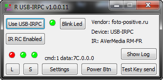
So far it looks like this:
- Minimizes to the notification area.
- At the click unfolds.
- The polling period is configured in Settings
- S - state saving in EEPROM
- L - load status from EEPROM
- Power Btn - performs the function fPCPwrSwitch (that is, presses the power button on the PC)
- Show log will show a list of events - sleep / wake up PC. (I have the power button sends to Sleep).
- The rest is test buttons.
- Clicking on one of the three light bulbs, switch accordingly - the LED, Relay1, Relay2 (tooltips will help you figure it out)
It seems all important told. If you have any questions, ask in the comments, I will try to answer.
Sources
- USB-IRPC firmware sources
- Schematic diagram, printed circuit board, sticker, picture-crib for assembly in DipTrace and png formats.
- MKey plugin sources
- Management program - alpha version on Delphi 2010.
Source: https://habr.com/ru/post/152034/
All Articles