IR remote for PC and sockets. Part 1
I do not have a TV. Totally. On the mezzanine somewhere there is an old little puzatik, but the antenna cable has long been minimized, and this TV is more of a mockery, except that it is too small to put in the kitchen.
Therefore, as a music center and TV, I use my PC. And everything would be fine, but laziness is not only the engine of progress, but also a factor that spoils the pleasure, forcing you to get up from the sofa, where you comfortably sat down with a cup of tea to start the program or turn off the speakers after watching the movie before going to bed.
There are many IR receivers, almost all of them can control a computer and can even turn it off, but they cannot turn it on . And at this moment the computer ceases to be as comfortable as a TV or stereo system. But the Igor HID project was not pleased with its software. Everything seems to be able, but inconvenient. And do not get into it, there is no source. That's why I gathered and made my project, open and accessible to all.
I made it from scratch to the complete set. And since my experience in the development and programming of electronic devices before it can be said was zero, then I think that everyone who is interested can repeat this.
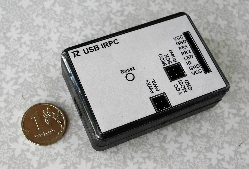
It is called USB-IRPC (USB Infrared Remote Personal Computer Control - “Yuesbi-IRPiSi” or IRPTS, as you prefer :). The letter R on the device itself is just a shortcut from my nickname.
An important advantage of the device is that it is software-compatible with the Arduino and in case of lack of confidence in its strength in the LUT can be made on the basis of the Arduino on the breadboard . This, of course, is not so compact and neat, not so cheap, but it is available to almost everyone, even special soldering skills will not be required.
If the desire for comfort is not alien to you and the idea to turn your computer into a media center, and at the same time to control the electrical outlets from the console with you, is interesting, then go ahead.
Please , if you are thinking about making the device after reading the article, ask questions in the comments . According to the experience of previous articles: there are quite a few of you and the questions you ask are the same :)
I'd rather answer all once, adding to the article or in the comments. Notifications of comments with questions I look through and try to answer.
I wanted to have the following features:
All this is currently working.
The functionality of the control program for the PC will be further expanded.
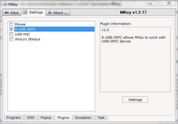
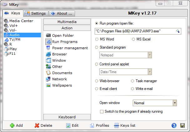
Also, a plugin was written for the popular MKey hotkey and multimedia key settings program , for those who do not want to understand my program, who don’t want to install another program or are already using MKey. The plugin makes a set of multimedia buttons from the IR remote. Give them what you want action. How to use, I will tell.
And where without them :)
But, all the software is open, the plugin for MKey does not require anything to read and adjust in it, and you can translate the inscriptions in my program if 7 buttons and 2 menu items cause problems with understanding or memorizing. Compile and modify yourself. Written in Delphi 2010, there are no proprietary software components.
')
I will tell you first how to do it on the basis of Arduino, then I will tell you how to do it yourself from scratch, and if there are any, I’ll write separately how to work with this device programmatically from a PC.
In fact, I started the device based on the Arduino. I used a cheap Arduino Pro Mini and a piece of breadboard:

" IRPC v1 "
This version had no connection with a PC, was only able to manage sockets and PC power, but it worked for me for more than 9 months - from November 2011.
As usual, we start with the purchase of parts.
1. Arduino (any with 5V power) - from about $ 7
Socket control module:
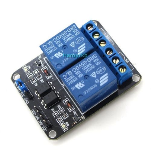
2. Board with a 220V relay, controlled by a 5V signal. If you have enough experience, you can do it yourself. I had this on the farm for a long time wondering where to adapt it:

Yes, there are 4 relays on it, and only 2 are used, because firstly - I only had 4-wire cable at hand, and for 4 relays I needed 6 (+ - and 4 signal), and secondly, it was only at hand 2 single sockets, and extension cords are not on a common bus, but I did not find the wires to each socket separately on the market. I got it for wild $ 17, but I bought it for a long time. Now it is on ebay for $ 3.82 , moreover, I advise you to take for this project with two relays - cheaper and more compact:
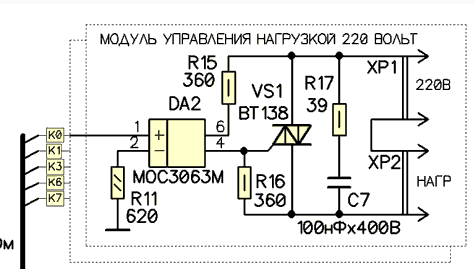
The disadvantage of the relay is that they click when switching. And if I hadn’t been doing nothing, I would have done BT138 with a galvanic isolation on the MOC3063 approximately like this (not mine, pulled a piece from the image found by Google):
3. 4-wire cable (you can use UTP, if there is, then more outlets can be made). Length - to have enough from the PC to the place where the block of sockets will lie.
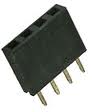
4. Connector PBS-4 for the final version or plug PLS-4, if you do on the Arduino.

5. Copper cable for connecting sockets to the relay - 2 pieces of about 20 centimeters.
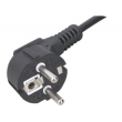
6. Electric cable with Schuko plug (CEE 7/4) or any other available at hand that will withstand the load:
7. Two wall mounted sockets (or more, if there are more relays and UTP cable) - about 30 rubles a piece.
8. A piece of plywood and a box for attaching the board with relays and sockets.
I mounted it in a regular cardboard box, fastened it to the piece of plastic with bolts and secured the cables with cable ties. It turned out like this:

" USB-IRPC 2-sockets 220v module "
Under the table, it looks pretty neat. Sockets are different, yes, there were no others :) I bought one, the second one remained from the upgrade of the wall socket to a double one.

" RPC-2PWR "
I leave the design delights at your discretion.
IR receiver module
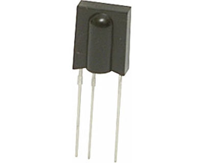
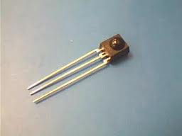
9. IR receiver TSOP1738, TSOP1736 or IRM_3638. Find an analogue - try it. My IRM3638 works best.
10. 10kΩ resistor
11. LED + resistor for 100-390 Ohm (which one is and take it), in extreme cases, you can do with the built-in Arduino on Pin 13 if you have neither a resistor nor an LED at hand, there will be no remote indication.
12. 2 PBS-4 connectors for the final version or PLS-4 plug if done on the Arduino.
13. A four-wire cable of such length that it is enough from the PC system unit (the device is installed inside) to the place where the receiver is conveniently fixed, so that it is visible from the sofa (I fixed it on the monitor leg).
PC power management module
14. PBS-2 connector for connecting to the motherboard instead of the power button.

15. PLS-2 connector, for connecting the power button from the case in parallel, so as not to lose the opportunity to use it. (you can simply buy one line of pins PLS-40 and bite off pieces with the right amount of pins from it with a nipper).

16. PC817 Optocoupler or equivalent. In theory, it costs 4-8 rubles, but on the Tsaritsyn radionke the huckster for it demanded 40 rubles.
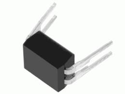
It is possible to use a relay, but it will turn out quite perverted, although it will work :)
17. Current-limiting resistor at 100-150 ohms of any power that is at hand.
PC interface (V-USB)
18. USB cable, we are only interested in USB A plug for connecting to a PC, on the other end there can be anything, we will cut it off anyway. So you can use any unnecessary cable. If only the whole was by the company.
19. 2 zener diodes at 3.6V is desirable 0.25 W, but more is possible.

20. 2 resistors for 68 ohms.
21. 1 2.2 kΩ resistor. There are no special requirements for power.
Soldering iron, solder, flux (rosin comes off), a little wire (yes any wiring that is on hand).
Any remote control with RC-5 encoding like this:

" IR RC "
The AverMedia remote control also works fine for me.
If you collect on a breadboard, you will need it and some wires, something like that :)
It only seems that there is a lot of everything, but in fact the costs are small. Is that you will buy everything in Chip and Dip :)
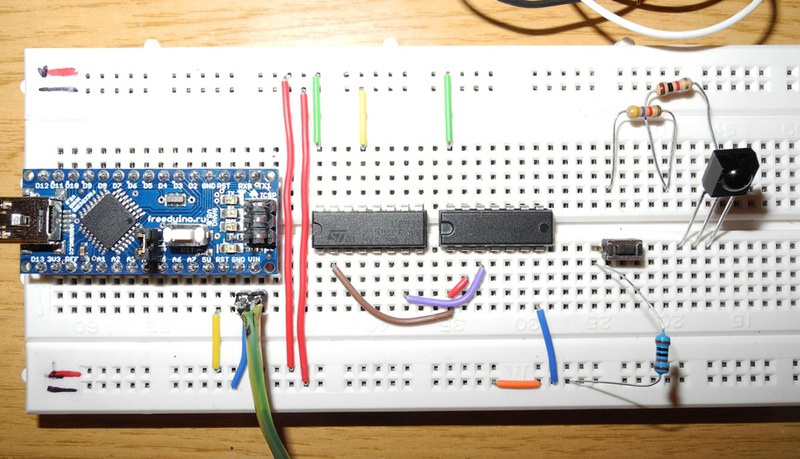
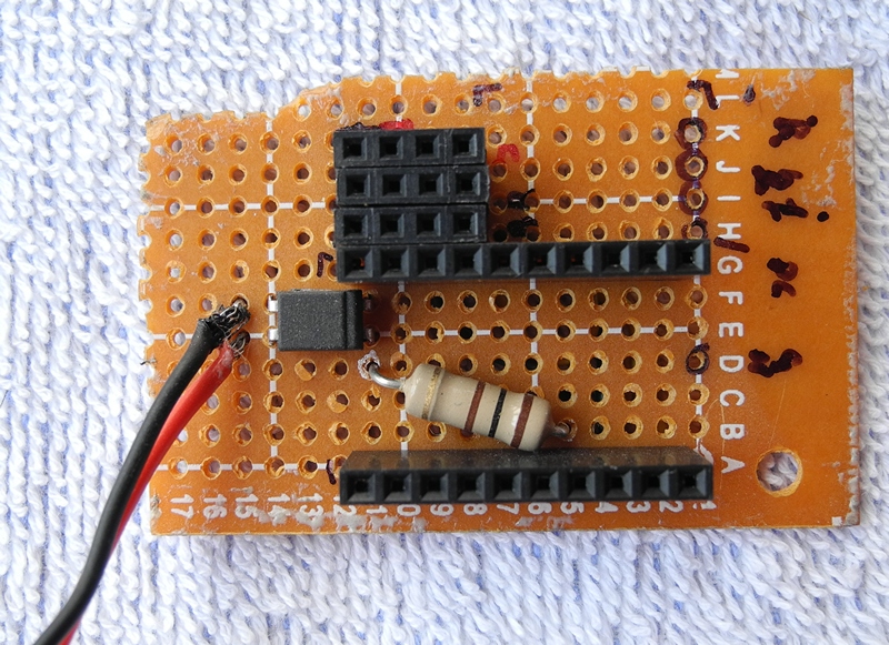
If you have an Arduino Pro Mini or Arduino nano, install it on a breadboard type Breadboard or, in my case, on a piece of the patch with a patch for soldering, soldering it there directly or using connectors so that you can remove:
The usual will have to connect to the breadboard wiring.
Signal leg directly to pin 8 (D8). Between the signal and power supply we turn on the resistor for 10k, and the remaining leg is grounded:
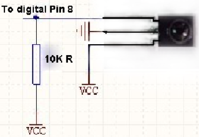
TSOP 1738 has a signal leg in the photo on the right:
Average - power (+ 5V), left - ground (GND).
These are three wires, the fourth - for the remote LED, I put it next to the receiver to show that the button is pressed. We connect it through an anode resistor to pin D9, cathode to ground.

It's all very simple:
For this we will need a 4-wire cable, at the end of the cable we solder PBS-4 in order to carefully put the plug on the board with the relay, the end to the development board is more convenient to do with the plug.
Now we assort sockets. If you took the power cable for the computer, cut off the end of the power cable, leaving only the Schuko plug and connect:
The brown wire - the phase - is fed to the relay, to the end that is normally open (drawn on the board).
Blue wire - zero, served directly on the outlet, on one of the contacts.
Yellow-green - protective grounding, connect to the ground loop of sockets.
( Nickel3000 corrected the coloring , in my description brown and blue were confused, although in this case it does not play a big role).
The middle relay contact, which will close with the phase when the relay switches, each output to its outlet (here we will need that copper wire from step 5) to the second contact.
You can ring the plug - two pins should ring on the blue and brown wires, yellow-green - on the grounding pins on the plug.
Put it all in the case (I just have a box):

" USB-IRPC 2-sockets 220v module "
The power button on the case simply closes the two contacts, we will do the same with the PC817 optocoupler.
When you apply 5V to the LED input, the resistance between the legs of the photodiode drops to almost zero (in fact, not to 0, but for our purposes it will come down). In order for the output of the microcontroller not to burn, turn on the current-limiting resistor in series.
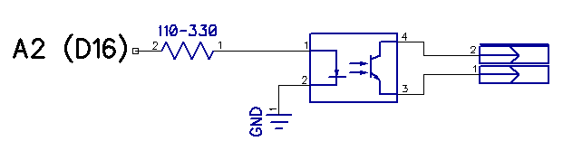
The resistor is connected to the A2 Arduino output, the second contact of the resistor to the 1st leg of the PC817 (marked with a dot). The second leg on the ground. To the 3rd and 4th we connect those two pins on the motherboard with two wires with a two-pin connector, which are designated as PWR + and PWR-, in parallel, we also connect a button from the PC case so that it can also close these contacts.
My project uses a USB software implementation for the AVR known as V-USB.
Take the USB cable, cut off the end that connected to the device
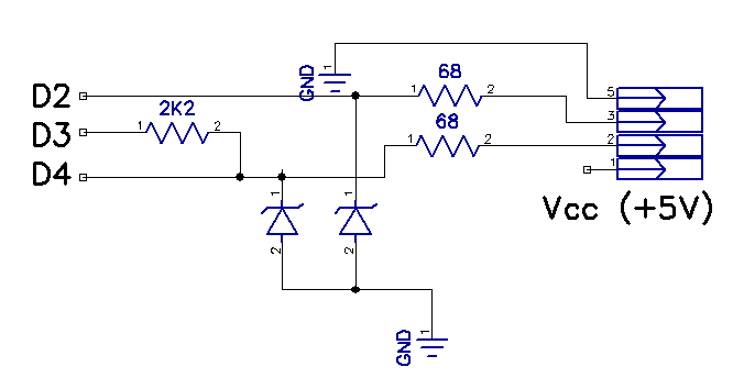
Red - VCC (pin 1 on the diagram on the right)
Black - GND (pin 5 on the diagram to the right)
Green - D + (pin 3 in the diagram on the right)
White - D- (pin 2 on the diagram on the right)
D + connect to pin 2 via a 68 Ohm resistor, D- connect to pin 4 via a 68 Ohm resistor.
connect the legs D3 and D4 (tightening) with a 2.2 kΩ resistor.
The zener diodes are connected in the opposite direction to the cathodes (the side with a black stripe on the housing) to - D2 and D4, respectively, the anodes to the ground.
VCC and GND are connected respectively to the same Arduino pins - it will be powered by USB.
Everything, our scheme is collected.
Carefully check everything in steps so as not to burn anything when connected.
If everything is checked - flashing with AvrDudeR . The fact is that I wrote the firmware in C, compiled using AVRToolchain. Project in Code :: Blocks. The source of the project lay out a little later on the project page
The settings are as follows:

COM port we specify the one that was assigned for Arduino, for Duemillanove speed 57600, for UNO 115200.
The firmware file we take this .
If everything was done successfully, you can disconnect the Arduino from the computer, now we connect our USB cable, which we wired on the board through zener diodes and resistors. At the same time it is better not to connect the tail of the Arduino itself and the connector of the project.
If everything is done correctly, the system will determine the USB Input Device.
The plugin allows you to assign any functions of the MKey to the remote buttons.
Download MKey , install, put my plugin to it in the Plugins folder.
Run MKey, on the settings tab, enable the R USB-IRPC plugin.
The setup is simple. Click Add, a window opens where you are prompted to press a button, press it on the remote, give it a name like on the remote and assign an action to it.
In order to control the relay programmatically, I need my program:
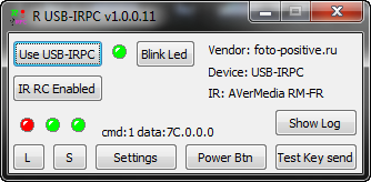
Now it allows:
A bit later there will be a functional:
I tried to tell as much detail as possible for the most beginners, because I constantly get a lot of simple, identical questions in the mail, so the volume of the article was large.
In the second part I will tell you how to make the device depicted in the very first photo independently from scratch, and not on the basis of Arduino.
I will get all the source code a bit and put it on the project page so that the functionality can be changed for myself.
If you wish, I will separately tell you what and how it works from the program point of view.
Part 2 - making from scratch and a software interface.
Therefore, as a music center and TV, I use my PC. And everything would be fine, but laziness is not only the engine of progress, but also a factor that spoils the pleasure, forcing you to get up from the sofa, where you comfortably sat down with a cup of tea to start the program or turn off the speakers after watching the movie before going to bed.
There are many IR receivers, almost all of them can control a computer and can even turn it off, but they cannot turn it on . And at this moment the computer ceases to be as comfortable as a TV or stereo system. But the Igor HID project was not pleased with its software. Everything seems to be able, but inconvenient. And do not get into it, there is no source. That's why I gathered and made my project, open and accessible to all.
I made it from scratch to the complete set. And since my experience in the development and programming of electronic devices before it can be said was zero, then I think that everyone who is interested can repeat this.
It is called USB-IRPC (USB Infrared Remote Personal Computer Control - “Yuesbi-IRPiSi” or IRPTS, as you prefer :). The letter R on the device itself is just a shortcut from my nickname.
An important advantage of the device is that it is software-compatible with the Arduino and in case of lack of confidence in its strength in the LUT can be made on the basis of the Arduino on the breadboard . This, of course, is not so compact and neat, not so cheap, but it is available to almost everyone, even special soldering skills will not be required.
If the desire for comfort is not alien to you and the idea to turn your computer into a media center, and at the same time to control the electrical outlets from the console with you, is interesting, then go ahead.
Please , if you are thinking about making the device after reading the article, ask questions in the comments . According to the experience of previous articles: there are quite a few of you and the questions you ask are the same :)
I'd rather answer all once, adding to the article or in the comments. Notifications of comments with questions I look through and try to answer.
So, the idea of the device
I wanted to have the following features:
- Turn on and off the computer with the remote control from the TV or any other IR remote control.
- Turn on and off the sockets, which are inserted into a desk lamp and speakers (two sockets are controlled separately).
- Manage sockets from a PC programmatically, so as not to look for the remote left on the couch when you sit in front of a computer or turn on speakers to operate the PC as an alarm clock on a schedule in the morning :)
- Run the program on the PC by pressing a button on the remote.
- Perform custom tasks by pressing the buttons - which I program.
All this is currently working.
The functionality of the control program for the PC will be further expanded.
- The device does not require drivers , it also works under Win7 x86, Win7 x64, Win 8 x64.
- Does not require administrator privileges when connecting and using.
- The system is defined as a HID device (USB Input Device).
- No additional .dll type lubusb is also required.
- Under Linux did not check, but I do not think that there will be problems. The truth is I can not write software - under Linux, I do not know how.
Also, a plugin was written for the popular MKey hotkey and multimedia key settings program , for those who do not want to understand my program, who don’t want to install another program or are already using MKey. The plugin makes a set of multimedia buttons from the IR remote. Give them what you want action. How to use, I will tell.
disadvantages
And where without them :)
- So far, in my opinion, the recognition of keystroke buttons is not perfect. Can do better sure. But this is corrected programmatically.
- Sewn functions that work without a PC can be changed only by recompiling the firmware, and for this you have to download AVR Toolchain - write the firmware in the Arduino IDE is a real torment for me, so I use Code :: Blocks. But pouring firmware into the Arduino is no problem. Even in the console will not have to climb. Later it will be possible to programmatically assign these functions to any buttons on the remote.
- The program is in English. I know that the overwhelming majority of problems are with English and I know the habit of Russifying everything.
- Russian inscriptions are almost always longer than English or have ugly cuts.
- The Russian language has not developed an unambiguous terminology for IT and the inscriptions on the interface elements are often more confused than clarified.
But, all the software is open, the plugin for MKey does not require anything to read and adjust in it, and you can translate the inscriptions in my program if 7 buttons and 2 menu items cause problems with understanding or memorizing. Compile and modify yourself. Written in Delphi 2010, there are no proprietary software components.
')
I will tell you first how to do it on the basis of Arduino, then I will tell you how to do it yourself from scratch, and if there are any, I’ll write separately how to work with this device programmatically from a PC.
Arduino USB-IRPC
In fact, I started the device based on the Arduino. I used a cheap Arduino Pro Mini and a piece of breadboard:
" IRPC v1 "
This version had no connection with a PC, was only able to manage sockets and PC power, but it worked for me for more than 9 months - from November 2011.
As usual, we start with the purchase of parts.
We will need:
1. Arduino (any with 5V power) - from about $ 7
Socket control module:
2. Board with a 220V relay, controlled by a 5V signal. If you have enough experience, you can do it yourself. I had this on the farm for a long time wondering where to adapt it:
Yes, there are 4 relays on it, and only 2 are used, because firstly - I only had 4-wire cable at hand, and for 4 relays I needed 6 (+ - and 4 signal), and secondly, it was only at hand 2 single sockets, and extension cords are not on a common bus, but I did not find the wires to each socket separately on the market. I got it for wild $ 17, but I bought it for a long time. Now it is on ebay for $ 3.82 , moreover, I advise you to take for this project with two relays - cheaper and more compact:
The disadvantage of the relay is that they click when switching. And if I hadn’t been doing nothing, I would have done BT138 with a galvanic isolation on the MOC3063 approximately like this (not mine, pulled a piece from the image found by Google):
3. 4-wire cable (you can use UTP, if there is, then more outlets can be made). Length - to have enough from the PC to the place where the block of sockets will lie.
4. Connector PBS-4 for the final version or plug PLS-4, if you do on the Arduino.
5. Copper cable for connecting sockets to the relay - 2 pieces of about 20 centimeters.
6. Electric cable with Schuko plug (CEE 7/4) or any other available at hand that will withstand the load:
7. Two wall mounted sockets (or more, if there are more relays and UTP cable) - about 30 rubles a piece.
8. A piece of plywood and a box for attaching the board with relays and sockets.
I mounted it in a regular cardboard box, fastened it to the piece of plastic with bolts and secured the cables with cable ties. It turned out like this:
" USB-IRPC 2-sockets 220v module "
Under the table, it looks pretty neat. Sockets are different, yes, there were no others :) I bought one, the second one remained from the upgrade of the wall socket to a double one.
" RPC-2PWR "
I leave the design delights at your discretion.
IR receiver module
9. IR receiver TSOP1738, TSOP1736 or IRM_3638. Find an analogue - try it. My IRM3638 works best.
10. 10kΩ resistor
11. LED + resistor for 100-390 Ohm (which one is and take it), in extreme cases, you can do with the built-in Arduino on Pin 13 if you have neither a resistor nor an LED at hand, there will be no remote indication.
12. 2 PBS-4 connectors for the final version or PLS-4 plug if done on the Arduino.
13. A four-wire cable of such length that it is enough from the PC system unit (the device is installed inside) to the place where the receiver is conveniently fixed, so that it is visible from the sofa (I fixed it on the monitor leg).
PC power management module
14. PBS-2 connector for connecting to the motherboard instead of the power button.
15. PLS-2 connector, for connecting the power button from the case in parallel, so as not to lose the opportunity to use it. (you can simply buy one line of pins PLS-40 and bite off pieces with the right amount of pins from it with a nipper).
16. PC817 Optocoupler or equivalent. In theory, it costs 4-8 rubles, but on the Tsaritsyn radionke the huckster for it demanded 40 rubles.
It is possible to use a relay, but it will turn out quite perverted, although it will work :)
17. Current-limiting resistor at 100-150 ohms of any power that is at hand.
PC interface (V-USB)
18. USB cable, we are only interested in USB A plug for connecting to a PC, on the other end there can be anything, we will cut it off anyway. So you can use any unnecessary cable. If only the whole was by the company.
19. 2 zener diodes at 3.6V is desirable 0.25 W, but more is possible.
20. 2 resistors for 68 ohms.
21. 1 2.2 kΩ resistor. There are no special requirements for power.
Soldering iron, solder, flux (rosin comes off), a little wire (yes any wiring that is on hand).
Any remote control with RC-5 encoding like this:
" IR RC "
The AverMedia remote control also works fine for me.
If you collect on a breadboard, you will need it and some wires, something like that :)
It only seems that there is a lot of everything, but in fact the costs are small. Is that you will buy everything in Chip and Dip :)
Understanding how to build and how it works
If you have an Arduino Pro Mini or Arduino nano, install it on a breadboard type Breadboard or, in my case, on a piece of the patch with a patch for soldering, soldering it there directly or using connectors so that you can remove:
The usual will have to connect to the breadboard wiring.
Connect the IR receiver.
Signal leg directly to pin 8 (D8). Between the signal and power supply we turn on the resistor for 10k, and the remaining leg is grounded:
TSOP 1738 has a signal leg in the photo on the right:
Average - power (+ 5V), left - ground (GND).
These are three wires, the fourth - for the remote LED, I put it next to the receiver to show that the button is pressed. We connect it through an anode resistor to pin D9, cathode to ground.
We connect the board with a relay
It's all very simple:
- VCC to +5 Arduino
- GND to GND Arduino (land)
- IN1 to pin 6
- IN2 to pin 5
For this we will need a 4-wire cable, at the end of the cable we solder PBS-4 in order to carefully put the plug on the board with the relay, the end to the development board is more convenient to do with the plug.
Now we assort sockets. If you took the power cable for the computer, cut off the end of the power cable, leaving only the Schuko plug and connect:
The brown wire - the phase - is fed to the relay, to the end that is normally open (drawn on the board).
Blue wire - zero, served directly on the outlet, on one of the contacts.
Yellow-green - protective grounding, connect to the ground loop of sockets.
( Nickel3000 corrected the coloring , in my description brown and blue were confused, although in this case it does not play a big role).
The middle relay contact, which will close with the phase when the relay switches, each output to its outlet (here we will need that copper wire from step 5) to the second contact.
You can ring the plug - two pins should ring on the blue and brown wires, yellow-green - on the grounding pins on the plug.
Put it all in the case (I just have a box):
" USB-IRPC 2-sockets 220v module "
We connect the PC power management
The power button on the case simply closes the two contacts, we will do the same with the PC817 optocoupler.
When you apply 5V to the LED input, the resistance between the legs of the photodiode drops to almost zero (in fact, not to 0, but for our purposes it will come down). In order for the output of the microcontroller not to burn, turn on the current-limiting resistor in series.
The resistor is connected to the A2 Arduino output, the second contact of the resistor to the 1st leg of the PC817 (marked with a dot). The second leg on the ground. To the 3rd and 4th we connect those two pins on the motherboard with two wires with a two-pin connector, which are designated as PWR + and PWR-, in parallel, we also connect a button from the PC case so that it can also close these contacts.
We connect to USB
My project uses a USB software implementation for the AVR known as V-USB.
Take the USB cable, cut off the end that connected to the device
Red - VCC (pin 1 on the diagram on the right)
Black - GND (pin 5 on the diagram to the right)
Green - D + (pin 3 in the diagram on the right)
White - D- (pin 2 on the diagram on the right)
D + connect to pin 2 via a 68 Ohm resistor, D- connect to pin 4 via a 68 Ohm resistor.
connect the legs D3 and D4 (tightening) with a 2.2 kΩ resistor.
The zener diodes are connected in the opposite direction to the cathodes (the side with a black stripe on the housing) to - D2 and D4, respectively, the anodes to the ground.
VCC and GND are connected respectively to the same Arduino pins - it will be powered by USB.
Everything, our scheme is collected.
Carefully check everything in steps so as not to burn anything when connected.
If everything is checked - flashing with AvrDudeR . The fact is that I wrote the firmware in C, compiled using AVRToolchain. Project in Code :: Blocks. The source of the project lay out a little later on the project page
The settings are as follows:
COM port we specify the one that was assigned for Arduino, for Duemillanove speed 57600, for UNO 115200.
The firmware file we take this .
If everything was done successfully, you can disconnect the Arduino from the computer, now we connect our USB cable, which we wired on the board through zener diodes and resistors. At the same time it is better not to connect the tail of the Arduino itself and the connector of the project.
If everything is done correctly, the system will determine the USB Input Device.
Management with the MKey plugin
The plugin allows you to assign any functions of the MKey to the remote buttons.
Download MKey , install, put my plugin to it in the Plugins folder.
Run MKey, on the settings tab, enable the R USB-IRPC plugin.
The setup is simple. Click Add, a window opens where you are prompted to press a button, press it on the remote, give it a name like on the remote and assign an action to it.
In order to control the relay programmatically, I need my program:
Now it allows:
- control relay and remote LED
- programmatically "push" the power button on the PC
- automatically disconnects from the device when the PC goes to sleep
- automatically connects when waking the PC.
- polls the device every 300 ms by default (configurable)
- displays the status of the relay and LED indicator, the code of the last button pressed from the moment of polling the remote control button
- enable / disable reception of infrared key presses.
- save the state of the relay to the EEPROM and read it from there. When enabled, the USB-IRPC reads the relay state from the EEPROM and sets them.
- the correspondence of the names to the codes of the buttons of the console is read from a simple text file, the selected file of the configuration of the console is loaded automatically when the program starts.
A bit later there will be a functional:
- launch programs at the touch of a button
- transfer button presses to the running program
- Assigning a device to independently react to the selected buttons on the console with one of the built-in functions: switching the relay, pressing the PC power button. (Now this functionality is built into the firmware for one particular console).
I tried to tell as much detail as possible for the most beginners, because I constantly get a lot of simple, identical questions in the mail, so the volume of the article was large.
In the second part I will tell you how to make the device depicted in the very first photo independently from scratch, and not on the basis of Arduino.
I will get all the source code a bit and put it on the project page so that the functionality can be changed for myself.
Part 2 - making from scratch and a software interface.
Source: https://habr.com/ru/post/151998/
All Articles