Enabling anything over HTTP without problems with OpenWRT
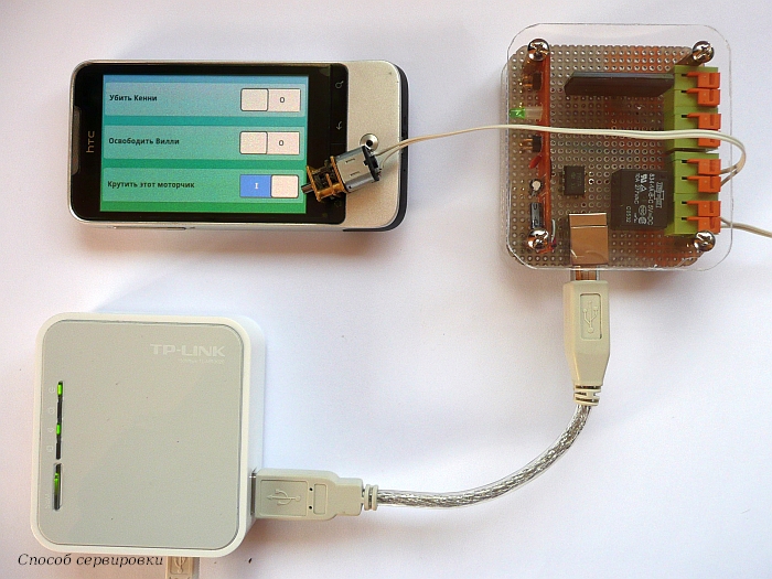
In the comments on the article about the experience of manufacturing the “Internet outlet” two comments caught my attention. One in which it was claimed that such a thing, in fact, was useless, seemed unfair to me - I remember well how I once needed, for example, to remotely “reset” one tricky little thing and think that I’m not alone. But the idea that it is possible to solve a similar question is easier and cheaper, using, for example, TP-LINK TL-MR3020 + OpenWRT seemed to me practical. I also decided to do without disassembling the device, programming and microcontrollers - in short, to make the decision as accessible as possible. And I almost got it!
As an output device, we use a regular USB keyboard. When I met at the supermarkets of the disgusting quality of the keyboard at ridiculous prices, I was always surprised - why would you need it? Yes, that's what for! In the keyboard there are three LEDs that can be programmed to control from any device that supports this keyboard. Replacing the LEDs with a control circuit - we get control of three loads. As a bonus - the possibility of further finishing the device for use as an input device. Of course, you can not shoot the gun on the sparrows, collect (or purchase) the simplest device on the microcontroller, which will have indisputable advantages (more inputs / outputs, normal logic levels, etc.). But the “keyboard” approach also has advantages - it is available to people unfamiliar with MCs who do not have a programmer. You can simply take and make a working device today, now. In addition, among the advantages:
- the solution is easily portable to other platforms: I didn’t check it, but in theory it can be plugged into any ASUS or D-Link peacefully distributing Internet from its own corner (if it has USB) - and it will work;
- the router can be used for its intended purpose;
- disassembling the router and interfering with its scheme is not required (and the TL-MR3020, by the way, is not easy to disassemble);
- no programming (except a small shell script) and compilation is required;
- All components can be purchased at a computer store (if you simply “flash the LED”, for real control you will have to buy a couple of available radio components), while the total costs will be less than 1500 rubles.
Install OpenWRT and configure the network interface.
For this step, you will actually need a router. My cost me 850r.
The model page on openwrt.org gives comprehensive instructions on flashing and allows us to use the trunk snapshot. I myself will timidly suggest taking the Attitude Adjustment beta 12.09 . Moreover, at the time of publication snapshots are not available on the openwrt website, and AA12.09 is finally uploaded.
The installation consists of several elementary operations:
- Configure the network connection of your PC to automatically obtain an IP address and connect the router with an Ethernet cable (after flashing, the WiFi interface will be disabled)
- Log into the router administration page (default address is 192.168.0.254 user: admin, password: admin)
- On the System Tools> Firmware upgrade tab, select the previously downloaded firmware, click “Upgrade” and wait until the download indicator reaches 100% twice.
- Since the default OpenWRT network parameters differ from TP-LINK's, the easiest way to re-initialize the interface is to disconnect and reconnect the ethernet cable.
- We go to the telnet router (192.168.1.1 - the address of the “fresh” OpenWRT by default) and set the password using the passwd command - now the router is accessible via SSH (and unavailable via telnet).
To install additional packages, you need access to the repository via the Internet, which requires its configuration as a client of the local network.
For example:
To configure a static IP in the segment 192.168.1.x do the following:
Where 192.168.1.1 is the gateway address in our network, and 192.168.1.222 is the unused IP, which will be assigned to our box. The “uci changes” command provides the ability to view all the changes made. I try not to neglect this opportunity, since a device with an incorrectly configured interface, being inaccessible from the outside, turns into a “zombie”. In case all the same trouble occurred, OpenWRT provides a “recovery mode”: when booting, as soon as the “WPS” button starts blinking, hold it down - the MR3020 will boot with the default network settings.
If DHCP is working on the network, you can configure it automatically:
The second line is optional, but can be extremely useful for finding a device. It will be possible to access the device not by IP, but by hostname, if the network supports it. If you want to avoid searching for a device on the network by 100%, use a static configuration.
It is also useful to prohibit the work of the dhcp server built into our TP-LINK:
Everything, you can disconnect our box from the computer (all the same, the ssh session was already terminated after the last command) and connect it to the router or switch.
uci set network.lan.proto=static uci set network.lan.ipaddr=192.168.1.222 uci set network.lan.netmask=255.255.255.0 uci set network.lan.gateway=192.168.1.1 uci set network.lan.dns=8.8.8.8 uci changes uci commit /etc/init.d/network restart Where 192.168.1.1 is the gateway address in our network, and 192.168.1.222 is the unused IP, which will be assigned to our box. The “uci changes” command provides the ability to view all the changes made. I try not to neglect this opportunity, since a device with an incorrectly configured interface, being inaccessible from the outside, turns into a “zombie”. In case all the same trouble occurred, OpenWRT provides a “recovery mode”: when booting, as soon as the “WPS” button starts blinking, hold it down - the MR3020 will boot with the default network settings.
If DHCP is working on the network, you can configure it automatically:
uci set network.lan.proto=dhcp uci set network.lan.hostname=etherelay uci commit /etc/init.d/network restart The second line is optional, but can be extremely useful for finding a device. It will be possible to access the device not by IP, but by hostname, if the network supports it. If you want to avoid searching for a device on the network by 100%, use a static configuration.
It is also useful to prohibit the work of the dhcp server built into our TP-LINK:
uci set dhcp.lan.ignore=1 uci commit /etc/init.d/dnsmasq restart Everything, you can disconnect our box from the computer (all the same, the ssh session was already terminated after the last command) and connect it to the router or switch.
Connecting the keyboard and checking the LED control
The H-WRT website informs us that only the kmod-usb-hid module is needed to install the keyboard.
Install it:
opkg update opkg install kmod-usb-hid It's time to connect the keyboard and see if it was identified:
root@OpenWrt:~# dmesg | tail [ 66.380000] hub 1-0:1.0: connect-debounce failed, port 1 disabled [ 68.780000] hub 1-0:1.0: connect-debounce failed, port 1 disabled [ 71.180000] hub 1-0:1.0: connect-debounce failed, port 1 disabled root@OpenWrt:~# Bummer! This is not what I expected. What is the matter?
A similar bug report is quickly located - the developers explain this behavior by the hardware limitations of the applied chipset. It seems that the on-board USB hub does not favor the low-speed device. Although at this moment the spirit of Zen evaporated without a trace - we will not give up and try to solve the problem by connecting the keyboard through an external USB hub:
root@OpenWrt:~# dmesg | tail [ 143.120000] usb 1-1: new high-speed USB device number 2 using ehci-platform [ 143.270000] hub 1-1:1.0: USB hub found [ 143.270000] hub 1-1:1.0: 4 ports detected [ 143.580000] usb 1-1.2: new low-speed USB device number 3 using ehci-platform [ 143.730000] input: Generic USB Keyboard as /devices/platform/ehci-platform/usb1/1-1/1-1.2/1-1.2:1.0/input/input0 [ 143.730000] generic-usb 0003:040B:2000.0001: input: USB HID v1.10 Keyboard [Generic USB Keyboard] on usb-ehci-platform-1.2/input0 [ 143.770000] input: Generic USB Keyboard as /devices/platform/ehci-platform/usb1/1-1/1-1.2/1-1.2:1.1/input/input1 [ 143.780000] generic-usb 0003:040B:2000.0002: input: USB HID v1.10 Mouse [Generic USB Keyboard] on usb-ehci-platform-1.2/input1 root@OpenWrt Much better. Let because of this I had to write “almost succeeded” at the beginning of the article and “the way of serving” in the photo, but this is how our “Generic USB Keyboard” was identified. Two “devices” are always created on the keyboard, but don’t even ask why this particular keyboard was also called a mouse ... One way or another, we’re ready for a “hardware hello shape” —to turn on the LED.
cat /dev/input/event0 > /dev/null & printf "\x00\x00\x00\x00\x00\x00\x00\x00\x00\x11\x00\x01\x00\x00\x00\x01" > /dev/input/event0 The “Caps Lock” LED should light up here. Those who are simply happy with this fact can move on to the next step. Those who can not move on without knowing what a crazy spell is given above - look into
muddled explanation:
For everything that happens with the keyboard (or another input device), an input event is generated that is visible in the corresponding file (in our case / dev / input / event0, but this is a special case due to the fact that no other input devices are connected). The structure of the event is defined in the input.h header file:
Where type indicates the type of input item (keyboard button or mouse / joystick movement, etc.), the code is the item-specific code for each type (for example, the key number for the EV_KEY key event will be passed here), and value is, respectively what effect and what magnitude (for devices supporting it) was produced. For example, when you press the "Q" key on the keyboard, we get:
where the first 8 bytes (505b 0ed9 000 * ****) is the event time, the next two bytes (0001) are the event type (EV_KEY), then two bytes of the key number (0010), which for the alphanumeric keys correspond to the scan code in Set 1. By the way, pressing any "pumped" keys like volume control, playback control, etc. sent to the second handler created for the keyboard (in our case / dev / input / event1). For them, the auto-repeat event is not generated, which can be very useful - remember, I wrote about the "bonus" ability of the device to work on input? The last 4 bytes (0000 0001 or 0000 0000) indicate that a press or release occurred, respectively. Packages consisting of zeros are special separating events EV_SYN, but I don’t know why type 4 events are needed. Definitions for types and codes are given in the same input.h , and are described in more detail in this document . Then the fun begins. Although most events are transmitted from the device to user space, some events can go in the opposite direction. This is done to support, for example, joysticks with feedback or (ta-dam!) LEDs. That is, by recording an event with type EV_LED, code LED_CAPSL and value 1 in / dev / event / input0, we will order the keyboard to light the “Caps Lock” LED. Enough details about working with input devices, especially USB, are told in the articles by Brad Hards (Brad Hards) The Linux USB Input Subsystem and Using the Input Subsystem (continuation of the first article, even with sample code to control the LED). It is a pity that I found them too late, when the problem has already been solved experimentally. By the way, I was very lucky - the last snapshots, as well as beta 12.09, have one feature , because of which the sending of events is unstable if the device file is not constantly read. This is what the command is for.
struct input_event { struct timeval time; __u16 type; __u16 code; __s32 value; }; Where type indicates the type of input item (keyboard button or mouse / joystick movement, etc.), the code is the item-specific code for each type (for example, the key number for the EV_KEY key event will be passed here), and value is, respectively what effect and what magnitude (for devices supporting it) was produced. For example, when you press the "Q" key on the keyboard, we get:
root@OpenWrt:~# cat /dev/input/event0 | hexdump 0000000 505b 0ed9 0009 6bdd 0004 0004 0007 0014 0000010 505b 0ed9 0009 6be6 0001 0010 0000 0001 0000020 505b 0ed9 0009 6bec 0000 0000 0000 0000 0000030 505b 0ed9 000a 2756 0004 0004 0007 0014 0000040 505b 0ed9 000a 275e 0001 0010 0000 0000 0000050 505b 0ed9 000a 2762 0000 0000 0000 0000 where the first 8 bytes (505b 0ed9 000 * ****) is the event time, the next two bytes (0001) are the event type (EV_KEY), then two bytes of the key number (0010), which for the alphanumeric keys correspond to the scan code in Set 1. By the way, pressing any "pumped" keys like volume control, playback control, etc. sent to the second handler created for the keyboard (in our case / dev / input / event1). For them, the auto-repeat event is not generated, which can be very useful - remember, I wrote about the "bonus" ability of the device to work on input? The last 4 bytes (0000 0001 or 0000 0000) indicate that a press or release occurred, respectively. Packages consisting of zeros are special separating events EV_SYN, but I don’t know why type 4 events are needed. Definitions for types and codes are given in the same input.h , and are described in more detail in this document . Then the fun begins. Although most events are transmitted from the device to user space, some events can go in the opposite direction. This is done to support, for example, joysticks with feedback or (ta-dam!) LEDs. That is, by recording an event with type EV_LED, code LED_CAPSL and value 1 in / dev / event / input0, we will order the keyboard to light the “Caps Lock” LED. Enough details about working with input devices, especially USB, are told in the articles by Brad Hards (Brad Hards) The Linux USB Input Subsystem and Using the Input Subsystem (continuation of the first article, even with sample code to control the LED). It is a pity that I found them too late, when the problem has already been solved experimentally. By the way, I was very lucky - the last snapshots, as well as beta 12.09, have one feature , because of which the sending of events is unstable if the device file is not constantly read. This is what the command is for.
cat /dev/input/event0 > /dev/null & I experimented first with the r31214 firmware, where there were no such features, so the LED on me came on right away - if that hadn't happened, then I would have been looking for the right way for a long time.Script
To automate the management of LEDs, we need a script. To blink them over HTTP in the next step, we will immediately put it in the / www / cgi-bin folder:
cd /www mkdir cgi-bin cd cgi-bin wget http://etherelay.googlecode.com/files/ctlrelay chmod +x ctlrelay Here is its text and description:
The constants EV_LED, LED_NUML, LED_CAPSL, LED_SCROLLL, as I said, are defined in input.h . Time does not bother us - we fill it with zeros. Of course, the code will turn out to be more compact if you form "events" on the fly, based on the command received, and not just send pre-filled templates in a switch, but it seemed to me that the basic idea was so clearer. We still need to read from the event file while writing to it, from which the proverbial crutch appeared. Again, this was not necessary in earlier assemblies, and most likely will not be needed in the future. But for now it is necessary to put up. The last fragment modifies the file of the current state of the LEDs, which consists of one approximately the following line:
#!/bin/sh KB_LEDS=/dev/input/event0 EV_LED="\x00\x11" LED_NUML="\x00\x00" LED_CAPSL="\x00\x01" LED_SCROLLL="\x00\x02" TURN_ON="\x00\x00\x00\x01" TURN_OFF="\x00\x00\x00\x00" DT_DUMMY="\x00\x00\x00\x00\x00\x00\x00\x00" # 16- NUM_ON=$DT_DUMMY$EV_LED$LED_NUML$TURN_ON NUM_OFF=$DT_DUMMY$EV_LED$LED_NUML$TURN_OFF CAPS_ON=$DT_DUMMY$EV_LED$LED_CAPSL$TURN_ON CAPS_OFF=$DT_DUMMY$EV_LED$LED_CAPSL$TURN_OFF SCROLL_ON=$DT_DUMMY$EV_LED$LED_SCROLLL$TURN_ON SCROLL_OFF=$DT_DUMMY$EV_LED$LED_SCROLLL$TURN_OFF #"", if ! ps | grep -qe "[c]at $KB_LEDS"; then cat $KB_LEDS > /dev/null & fi # "" command GET- # - if [ -z "$QUERY_STRING" ]; then COMMAND=$1; else COMMAND=`echo "$QUERY_STRING" | sed -n 's/^.*command=\([^&]*\).*$/\1/p'` printf "Content-type: text/plain\r\n\r\n" fi # case $COMMAND in num_on) printf $NUM_ON > $KB_LEDS;; num_off) printf $NUM_OFF > $KB_LEDS;; caps_on) printf caps_on > /var/rrr printf $CAPS_ON > $KB_LEDS;; caps_off) printf caps_off > /var/rrr printf $CAPS_OFF > $KB_LEDS;; scroll_on) printf $SCROLL_ON > $KB_LEDS;; scroll_off) printf $SCROLL_OFF > $KB_LEDS;; num_pulse) printf $NUM_ON > $KB_LEDS sleep 1 printf $NUM_OFF > $KB_LEDS ;; caps_pulse) printf $CAPS_ON > $KB_LEDS sleep 1 printf $CAPS_OFF > $KB_LEDS ;; scroll_pulse) printf $SCROLL_ON > $KB_LEDS sleep 1 printf $SCROLL_OFF > $KB_LEDS ;; *) WRONG_ARG=1;; esac # if [ -z $WRONG_ARG ] then STATE_FILE=/var/ledstate DEFAULT_STATE={\"num\":false,\"caps\":false,\"scroll\":false} if ! [ -e $STATE_FILE ]; then echo $DEFAULT_STATE > $STATE_FILE; fi AFFECTED_LED=`echo $COMMAND | sed -r -e 's/_[az]+$//'` NEW_STATE=`echo $COMMAND | sed -r -e 's/^[az]+_//' -e 's/on/true/' -e 's/off|pulse/false/'` sed -i -r 's/"'"$AFFECTED_LED"'":[az]+/"'"$AFFECTED_LED"'":'"$NEW_STATE"'/' $STATE_FILE fi The constants EV_LED, LED_NUML, LED_CAPSL, LED_SCROLLL, as I said, are defined in input.h . Time does not bother us - we fill it with zeros. Of course, the code will turn out to be more compact if you form "events" on the fly, based on the command received, and not just send pre-filled templates in a switch, but it seemed to me that the basic idea was so clearer. We still need to read from the event file while writing to it, from which the proverbial crutch appeared. Again, this was not necessary in earlier assemblies, and most likely will not be needed in the future. But for now it is necessary to put up. The last fragment modifies the file of the current state of the LEDs, which consists of one approximately the following line:
{"num": true, "caps": false, "scroll": false} If there is no such file, it will be created with all the values “false”. In OpenWRT, the / var / directory is in RAM, which means that the file is created after each reboot, when all the LEDs are turned off. Cozy shemka! I read the parameters from the HTTP request, probably here (I read it a long time and did not save the link, only a line of code, but it’s very similar here). The script displays "Content-type: text / plain" if it is called via CGI, because otherwise the result of the query will be 502 (Bad Gateway), and not 200 (OK), which is not fatal, but ugly.Now control LEDs easily. To enable, say, the LED "Scroll Lock", we write:
./ctlrelay scroll_on Turn off:
./ctlrelay scroll_off You can still blink (scroll_pulse). As the already respected Anant Agarwal says here already: “I could do this all day. This is so much fun! ” But still, move on to the next stage and create ...
Web interface
What is a web interface without a web server? Check its availability:
opkg status uhttpd If there is a Status: install user installed line in the output (and this will be the case if you use Attitude Adjustment 12.09 beta) then the server is already installed. Otherwise, install it and configure its launch:
opkg update opkg install uhttpd /etc/init.d/uhttpd enable /etc/init.d/uhttpd start Next we need a web page:
At first, I wanted to use jQuery.get (), but then I considered it unnecessary to involve JQuery for the sake of just a couple of GET requests. We have two JavaScript functions. The first, command (action) , runs our script, passing the “command” in the “command” parameter of the GET request. Which one is defined in the onclick events of the controls. It does not look very elegant, no doubt, but it gives a good idea of how everything works. The second function, get_status (), runs on the onload event , requests a file with the current state of the LEDs (the one that forms at the end of the script) and reflects it on the page controls. By incredible coincidence, the state file is a JSON representation of an associative array, and we very easily get access to the data using JSON.parse () . Repeating the request every half second allows you to track status changes made from another client. The addition to the url fuie = Math.random () is needed so that the address is unique each time - then the browser will not be able to refuse the page request, finding that it is already in the cache. As you can guess from the name of the variable, it is especially prone to this behavior of Internet Explorer.
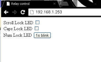
<!DOCTYPE html> <html> <head> <title>Relay control</title> <meta http-equiv="content-type" content="text/html; charset=utf-8"> <script type="text/javascript"> function command(action) { url="/cgi-bin/ctlrelay?command="+action; url=url+"&fuie=" + Math.random(); var xmlhttp=new XMLHttpRequest(); xmlhttp.open("GET",url,false); xmlhttp.send(); } function get_status() { var xmlhttp=new XMLHttpRequest(); xmlhttp.onreadystatechange=function() { if (xmlhttp.readyState==4 && xmlhttp.status==200) { ledstate = JSON.parse(xmlhttp.responseText) for (led in ledstate) { document.getElementById(led).checked=ledstate[led] } } } xmlhttp.open("GET","/ledstate?fuie="+ Math.random(),false); xmlhttp.send(); setTimeout("get_status()",500); } </script> </head> <body onload="get_status()"> <div class="controls"> <div class="control"> <label for="scroll">Scroll Lock LED</label> <input id="scroll" type="checkbox" onclick="if (this.checked) command ('scroll_on'); else command ('scroll_off')"> </div> <div class="control"> <label for="caps">Caps Lock LED</label> <input id="caps" type="checkbox" onclick="if (this.checked) command ('caps_on'); else command ('caps_off')"> </div> <div class="control"> <label for="num">Num Lock LED</label> <button id="num" type="button" onclick="command('num_pulse')">1s blink</button> </div> </div> </body> </html> At first, I wanted to use jQuery.get (), but then I considered it unnecessary to involve JQuery for the sake of just a couple of GET requests. We have two JavaScript functions. The first, command (action) , runs our script, passing the “command” in the “command” parameter of the GET request. Which one is defined in the onclick events of the controls. It does not look very elegant, no doubt, but it gives a good idea of how everything works. The second function, get_status (), runs on the onload event , requests a file with the current state of the LEDs (the one that forms at the end of the script) and reflects it on the page controls. By incredible coincidence, the state file is a JSON representation of an associative array, and we very easily get access to the data using JSON.parse () . Repeating the request every half second allows you to track status changes made from another client. The addition to the url fuie = Math.random () is needed so that the address is unique each time - then the browser will not be able to refuse the page request, finding that it is already in the cache. As you can guess from the name of the variable, it is especially prone to this behavior of Internet Explorer.
A small nuance - the browser, of course, does not have access to the / var folder on the server, so we will give it the opportunity to read the ledstate file from where it “reaches out” using the symlink:
ln -s /var/ledstate /www/ledstate A link to download this page, slightly modified, can be found almost at the very end of the article. Now you can blink the LEDs of the keyboard, poking at the checkboxes. But, not even considering the fact that now it’s impossible to surprise anyone with a flashing LED, you will have to agree that it is absolutely useless from a practical point of view. Therefore, let's get down to iron!
Scheme
You can already disassemble the keyboard and pull the board out of it:
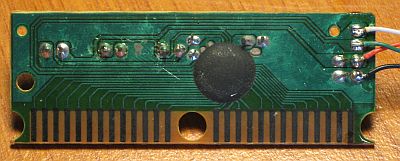
The scheme of switching on the LEDs of the keyboard is represented by the following (very simplified) model (for the on state):
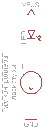
Scheme 1. Turning on the keyboard LED
Three proven “clavs” from the “scrubber” segment had just such an inclusion of LEDs, only their currents differ - usually around 18mA, but sometimes 3mA. It must be borne in mind that other schemes are possible.
The simplest is if you need to switch a small voltage and current (remote "Reset" of any device or emulation of other buttons / logic signals). You can do the usual optocoupler:
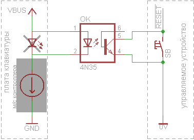
Scheme 2. Formation of a logical signal
To control the device with mains powered, we take a solid-state relay:

Diagram 3. Control of a solid-state relay
I used the domestic relay K293KP13P because of the price of 170 rubles. The maximum current in the load for which it is designed - 1A. The current through the control LED should not be lower than the minimum (in the documentation it is designated I F min) for the type of relay used. If the keyboard board gives less current (unsolder one lead of the LED and measure the current in the gap) - an additional transistor switch will help:

Scheme 4. Connecting a solid-state relay through a key
He will save if you use a solid-state relay, voltage controlled or "classic" electromechanical relay:
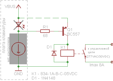
Diagram 5. Control of an electromechanical relay
A solid-state relay is rather expensive, and the more powerful the more expensive. A regular relay gives more “amps per ruble”, but it has its drawbacks. Among them - the big consumed current in the included state. If you simultaneously turn on three relays of the same model as in the diagram, the current consumed from USB will be almost 300 mA. If you do not want to “milk” the port so much - connect the emitter not to it (the dotted line in the diagram), but to an independent source.
Circuits 4 and 5, of course, work only on keyboards where the LEDs are turned on according to the circuit with a “common anode” (check the resistance between the anodes of the diodes and the “plus” of the board - it should be 0 Ohm). If reluctance to bother with this - you can use low-power optorele instead of a key. It turns on instead of the standard LED and operates at a current on the LED from 5 to 25 mA, that is suitable for all variants of keyboards with a probability of 99%. If you need to switch the voltage up to 60 V and current up to 300 mA - you can remove the relay and use the optolera directly.
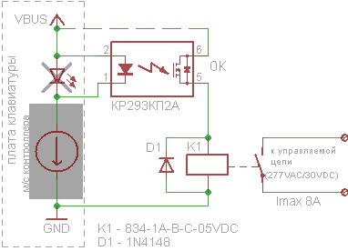
Diagram 6. Control of an electromechanical relay using an optorele
There are many simplifications in the scheme and its implementation:
What you always have to take into account is elementary electrical safety. Even a test device — especially a test device, which will most likely hang around somewhere on the wiring or will be forgotten to be included, among other things, junk on the table — must be protected from accidentally touching live parts, if it provides for connection to the network. Otherwise, an absolutely real electric current can flow through you.Not bad to add a fuse to the switched circuit. The transistor in circuit 5 operates with an almost maximum collector current — it is desirable to take a smaller response current, or at least a more powerful transistor. At the outputs of the solid-state relay you need to put a damping RC-chain when working on a motor or other inductive load. The components were selected only according to the criterion of availability and price in the nearest (to me) very expensive radio store - if you have a choice, you can pick up a solid body from a normal seller for the desired current with a wide range of I F and then close the issue with switching. In addition, the presented switching model is inaccurate: the keyboard board behaves as a current source in relation to our “LED” only when the anode voltage is 2.5V and higher - I tried, if possible, to provide a voltage drop similar to that of the replaced LED, so that The board "did not feel" the substitution.
I collected options 3 and 6 on the breadboard, it turned out like this:
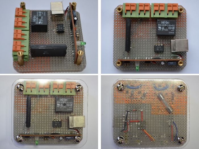
Despite the fact that this is nothing more than a “proof of concept”, I wanted to “bring beauty” a little, even in my own perverted interpretation. Such now times: the appearance is valued not less, and sometimes unnecessarily more functional load. Which brings us to the next stage.
')
Cosmetics and Demonstration
From the HTML - interface for kilometer carries the botanist, biker shirts with pellets and pasta from a glass jar:
Let's try to somehow brighten it up.
- Since my artistic abilities are at zero, and the taste is somewhere near them -
I stole the idea from here,I got inspiration (and some css) here: http://www.seanslinsky.com/demo/ios-toggle-switches/ . - With the help of a gradient generator, mudcu.be/bg made a non-dull
wallpaperbackdrop. - The cool toggle generator proto.io/freebies/onoff creates buttons that work in almost all browsers — even in Opera, if you make them square, and even in IE, if it is> = 9.
- Since on different systems the zoom works differently - we make the zoom buttons inside the davidwalsh.name/change-text-size-onclick-with-javascript page .
CSS does not make sense to give, because 90% generated automatically, and HTML - 90% of the above. Therefore, I just write as to download:
cd /www mkdir luci mv index.html luci wget http://etherelay.googlecode.com/files/index.html wget http://etherelay.googlecode.com/files/style.css The second and third lines "hide" the file of the web-interface of the router (if it is installed) into a separate folder, now it is available at the address of the router_address / luci. And the “main” page accessible to the server’s address is ours.
And finally, they say that a picture is worth a thousand words. . , - .
Update: nm11 , - (, wizard lumos ):
uci set uhttpd.main.config=/etc/httpd.conf uci commit uhttpd echo "/:wizard:lumos" > $(uci get uhttpd.main.config) /etc/init.d/uhttpd restart Source: https://habr.com/ru/post/151982/
All Articles