Moon and msp430
Good day! Just want to say that I am not campaigning for msp430, but since I bought it, I must, as they say, apply it. Again, the community complained about the lack of specifics in posts about this platform. History means the following. The task was to acquire a night light in the bedroom. It is said that we must go to IKEA, there is. But easy ways are not for us. The lamp was selected taking into account the subsequent possible modernization.
So, the carcass:
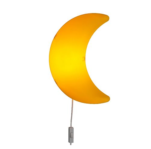
Initially sharpened chambered for E14. But in the storeroom, the 5-meter LED strip was gathering dust for a long time. Patron - off. Tape glued around the perimeter from the inside. The self-adhesive layer has dried, but, thank God, it stopped stink terribly. I had to use superglue. It turned out about the following:
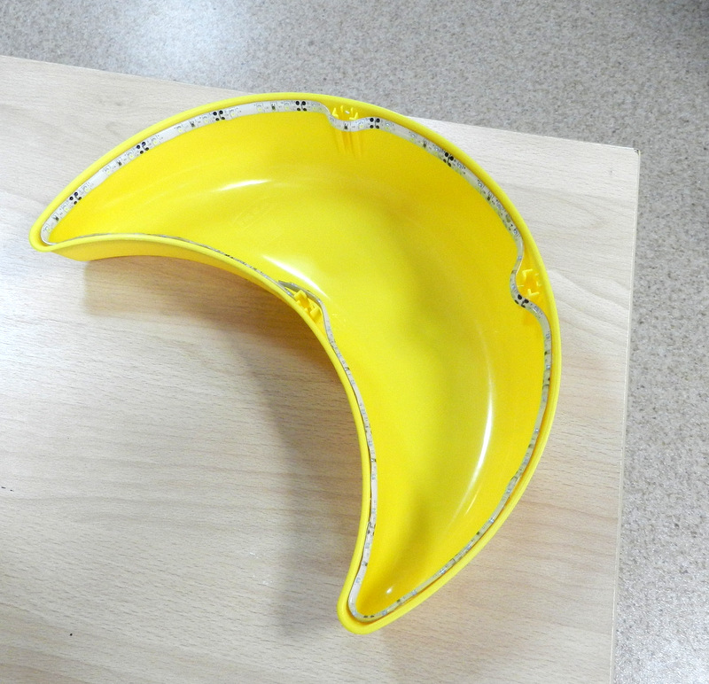
The emitter is ready. The youngest of the bundled Launchpad - msp430g2452 was chosen as the control microcontroller. Do not use the entire debug board. The big pain, and the controller, which is used in the programmer / emulator, put an eye. He took a dead keychain from the car alarm, cut out a board from it. Did not begin to remove the assembly process. The result is this:
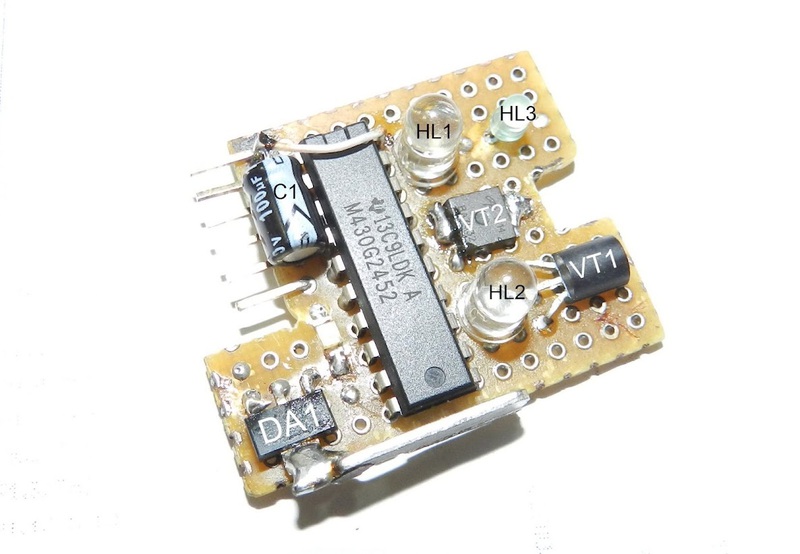
I will explain a little on the details.
VT1 is the key that controls the IR LED;
VT2 - field switch commuting LED strip;
HL1 - IR - phototransistor;
HL2 - IR - LED;
HL3 - green LED;
C1 - blocking electrolyte on nutrition
DA1 - 3.3V stabilizer. By the way, a small radiator is soldered to it.
reverse side of the board:
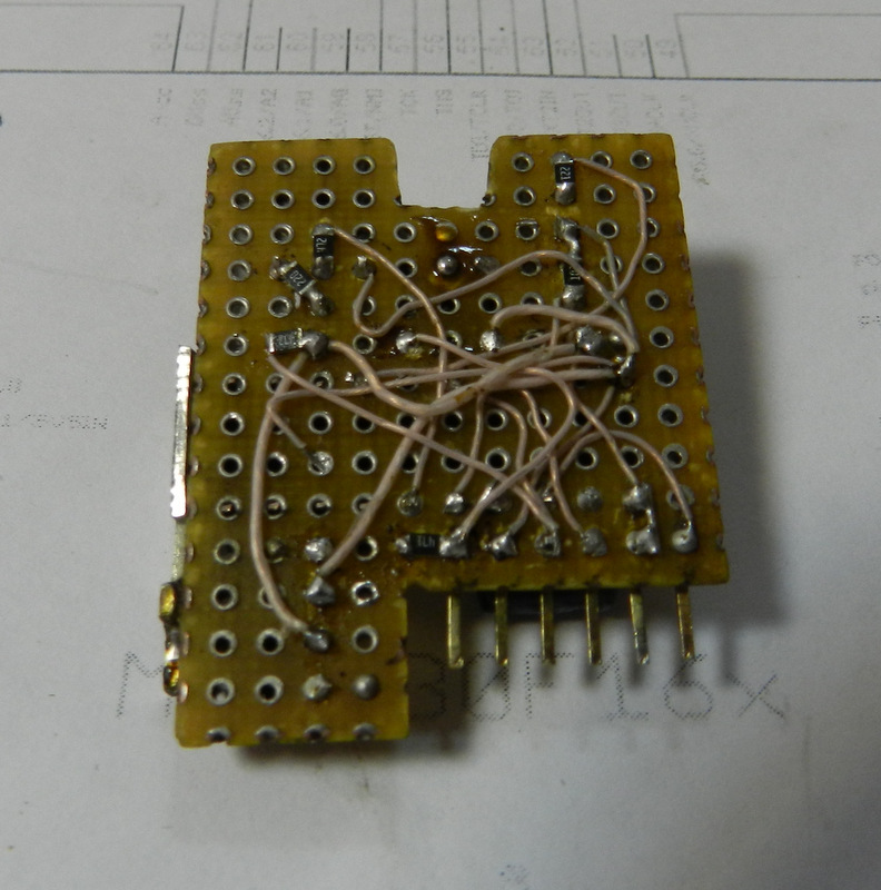
bottom-right pieces of wire - debug-programming connector. A debugger / programmer with a magic adapter is connected to it:

Further construction:
The previously tested infrared distance sensor on the L-53F3C LED and the L-53P3C phototransistor was chosen as a contactless sensor. With this couple previously dealt with. Built on them infrared bumper for the robot. Proved well. The principle of the sensor is simple. The processor first measures the voltage on the phototransistor with the IR LED off. Then turns on the IR LED and again measures the voltage on the phototransistor. The difference in measurements will depend on how strongly the surrounding objects reflect IR radiation. The closer the subject, the more reflected light enters the phototransistor. For reliability, I carried out 3 measurements of each state. The result averaged.
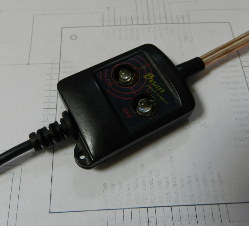
Here is the switch in the case:

complete:
Just doing on / off is not sporting. For a start, made FadeIn and FadeOut. Those. smooth increase of brightness to the maximum, and smooth shutdown. To adjust the brightness used hardware PWM. Under the curtain added the function of manual brightness control. Hold your hand for a long time - the brightness gradually increases. Then decreases.
The source in the picture (you need to unpack winrar th)
Fixed source in the picture (see comments)
Of the features of the program.
We work with the ADC (measure the voltage on the photodiode);
We work with timer0 (needed for hardware PWM, still blink LED HL3);
We do not work with WDT, although it would not be bad to escape from sudden hangs. Not yet observed, so do not touch.
The exponential brightness-PWM is used, since linear variation of the duty cycle does not lead to a linear change in brightness.
Actually, the result of the work:
Ps. Drew a scheme.

So, the carcass:
Initially sharpened chambered for E14. But in the storeroom, the 5-meter LED strip was gathering dust for a long time. Patron - off. Tape glued around the perimeter from the inside. The self-adhesive layer has dried, but, thank God, it stopped stink terribly. I had to use superglue. It turned out about the following:
The emitter is ready. The youngest of the bundled Launchpad - msp430g2452 was chosen as the control microcontroller. Do not use the entire debug board. The big pain, and the controller, which is used in the programmer / emulator, put an eye. He took a dead keychain from the car alarm, cut out a board from it. Did not begin to remove the assembly process. The result is this:
I will explain a little on the details.
VT1 is the key that controls the IR LED;
VT2 - field switch commuting LED strip;
HL1 - IR - phototransistor;
HL2 - IR - LED;
HL3 - green LED;
C1 - blocking electrolyte on nutrition
DA1 - 3.3V stabilizer. By the way, a small radiator is soldered to it.
reverse side of the board:
bottom-right pieces of wire - debug-programming connector. A debugger / programmer with a magic adapter is connected to it:
Further construction:
The previously tested infrared distance sensor on the L-53F3C LED and the L-53P3C phototransistor was chosen as a contactless sensor. With this couple previously dealt with. Built on them infrared bumper for the robot. Proved well. The principle of the sensor is simple. The processor first measures the voltage on the phototransistor with the IR LED off. Then turns on the IR LED and again measures the voltage on the phototransistor. The difference in measurements will depend on how strongly the surrounding objects reflect IR radiation. The closer the subject, the more reflected light enters the phototransistor. For reliability, I carried out 3 measurements of each state. The result averaged.
Here is the switch in the case:
complete:
Just doing on / off is not sporting. For a start, made FadeIn and FadeOut. Those. smooth increase of brightness to the maximum, and smooth shutdown. To adjust the brightness used hardware PWM. Under the curtain added the function of manual brightness control. Hold your hand for a long time - the brightness gradually increases. Then decreases.
The source in the picture (you need to unpack winrar th)
Fixed source in the picture (see comments)
Of the features of the program.
We work with the ADC (measure the voltage on the photodiode);
We work with timer0 (needed for hardware PWM, still blink LED HL3);
We do not work with WDT, although it would not be bad to escape from sudden hangs. Not yet observed, so do not touch.
The exponential brightness-PWM is used, since linear variation of the duty cycle does not lead to a linear change in brightness.
Actually, the result of the work:
Ps. Drew a scheme.
')
Source: https://habr.com/ru/post/151940/
All Articles