Laser ball bearing

Photo © fabymartin.com
Recently, an interesting article was published in the journal New Scientist about the development of lasers with variable wavelength . After reviewing the original work on arXiv.org, and looking at the experimental setup, I decided that this device was simple enough to assemble it myself.
The basic idea is to introduce into the working body of the dye laser a number of reflective balls and shake them so quickly that they behave as if they are in a suspended state. Then, the dye is pumped by an external radiation source, and by changing the oscillation frequency, it is possible to filter out various wavelengths of the laser radiation that is emitted by the dye.
The entire installation consists of six components:
- Dye for the laser, in this case Rhodamine B
- Many small balls from the bearing
- A small glass container, which will be balls and dye
- Speaker as a source of mechanical vibrations
- Laser for pumping dye
- Variable frequency generator
')
Laser module and pumping device
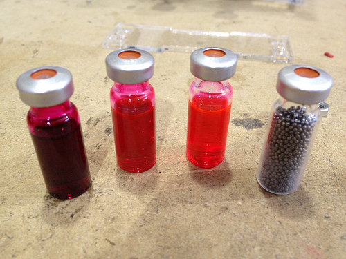
Components for the laser module. From left to right: solutions of rhodamine B 0.1 mol / l, 0.01 mol / l and 0.001 mol / l, 1750 steel balls with a diameter of 1 mm.
Hereinafter all the pictures are clickable. - Approx. trans.
Steel balls and a vial of borosilicate glass - the parts that were easiest to get. Find rhodamine was a little more difficult. Comrade Protospace was kind enough to prepare me three different solutions of rhodamine B in methanol: 0.001 mol / l, 0.01 mol / l, and 0.1 mol / l. When the balls were washed off the oil with acetone and then dried, all that remained was to pour them into the vial of rhodamine.
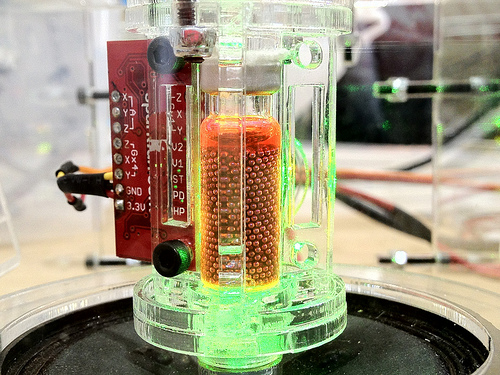
Radiation of rhodamine B
The next step was to find a pumping source powerful enough to overcome the rhodamine generation threshold. In the end, I settled on a source with a wavelength of 532 nm with a capacity of 30 mW and decided not to use a more powerful for security reasons. The installation was planned to show on Maker Faire YYC , and I did not want to damage anyone's eyes. I'm still trying to find out if this power was enough to overcome the dye generation threshold, or if the yellow light emitted by rhodamine is actually spontaneous radiation, and not forced.
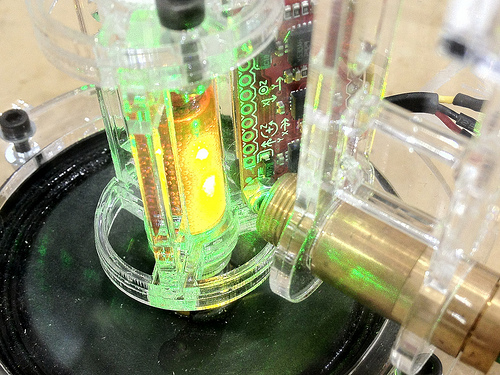
Spontaneous or stimulated emission?
Speaker installation
Originally, I was going to simply glue the laser module directly to the speaker. However, after I successfully killed one speaker, gluing the voice coil to the magnet, I decided to make a design that allows you to easily replace the modules.The final design contained a small rare-earth magnet, mounted on the speaker coil, and a metal washer at the bottom of the laser module. Magnetic mount shown in the picture below. I also made sure that the magnet is far enough away from the balls so that they do not stick together.

Laser module and pumping device close-up
In an attempt to follow the original article as precisely as possible, I included an accelerometer in the design to measure the intensity of vibrations. The old inertial measuring unit Razor with six degrees of freedom was used (3-axis accelerometer + 3-axis gyroscope. - Appro. transl. ) . He remained from another project, where he was replaced by a new, more compact model . Five of the six degrees of freedom here were superfluous.
Oscillation generator
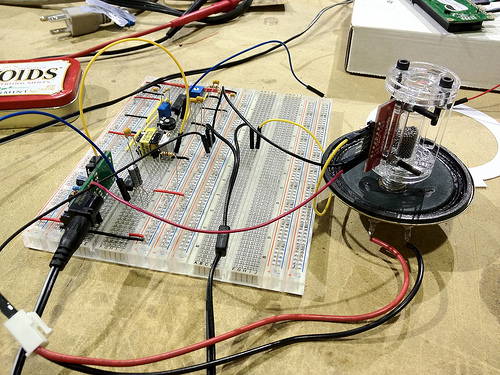
XR2206 generator and LM386 amplifier
I assembled the generator on the XR2206 microcircuit according to the scheme given in the datasheet. Most of the work here was to select frequency assignment resistors and capacitors to get the desired frequency range using only the ratings that I had available. The result is a fairly simple circuit that can generate both a sine and a triangular signal with a frequency of 35 to 45 Hz.
From the output of the function generator, the signal is fed to an audio transformer of 1: 1 in order to bring the signal to zero to the potential of the common wire, and not the virtual ground of the generator. Then the signal goes to the LM386 amplifier, which is switched on according to the 20 dB gain circuit.
I ran into a problem that the XR2206 is sensitive to temperature changes. In direct sunlight for 2 hours, the frequency drifted to 15 Hz.
Maker Faire YYC

Finished enclosures
To participate in the Maker Faire YYC, I wanted the installation to be an online tutorial, not a simple demonstration. Using laser cutting, I made pretty acrylic cases with a waveform switch (sine or triangle), amplitude and frequency controls. This was great, as it was possible to demonstrate how frequency and amplitude affect the movement of balls in a liquid.
Fabi Martin made a whole bunch of photos from the event , among them there are several pictures in which I and my laser explain to the general public the basics of laser physics.
Further experiments
There are many more experiments that I would like to conduct, and improvements that I would like to do.First of all, I want to switch to a more powerful pumping laser, somewhere in the region of 200 mW or even 1 W, to be absolutely sure of overcoming the rhodamine generation threshold. From now on, I will place the entire unit in a closed box, so as not to see it during the experiments and not to burn my eyes.
I also want to get a good spectrometer to properly monitor the output radiation and better see the wavelength shift described in the original article. I suspect that an accelerometer with a wider range may also be required: the maximum acceleration of the diffuser reaches 30 g.
Making a normal PCB for a control circuit would also be nice. I ran into problems on the mockups where the long wires cause weakening and noise in the signal. As soon as I deal with all these questions and complete the main experiments, it would be great to mount the laser module and the control circuit in a single package.
Source: https://habr.com/ru/post/151840/
All Articles