Doomsday Button or Hardware Hot Key
Probably, each of the readers faced with the fact that he lacks hot keys. The most running and simple combinations are occupied, and the rest require the dexterity of a bayan player. This is especially true for laptops, where the keys are reduced. In particular, for the MacBook, where a number of multimedia keys are combined with functional ones.
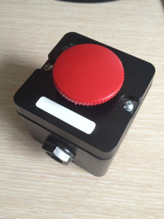
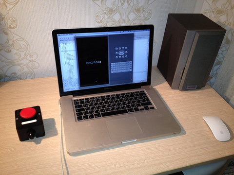
So for the “Make Project” action, I wanted to have a separate button. This idea lived somewhere in the subconscious for quite a long time, until one day the start button of the machine at 660V 10A caught my eye. Details how it was possible to connect it to a laptop via bluetooth, read under the cut.
First of all, I wanted the device to be wireless and not require the installation of drivers.
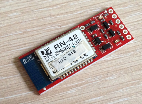
After a bit of searching, I took the Bluesmirf HID modem from Sparkfun as a basis.
')
Another option was Bluegiga, but since On the Sparkfun website one could buy other necessary components, then I stopped at the first one. This modem is defined as a wireless keyboard and can be controlled via the UART. As control “brains”, I decided to use the controller ATTiny2313.
A listing of what I needed:
• Bluesmirf HID modem
• ATTiny2313 + substrate 20 pins
• Scarf 11x16 holes
• ISP AVR programmer, any suitable, cheap.
• FTDI TTL cable. In fact, this is a normal USB-to-serial cable, but with an output voltage of 5V. This cable is very necessary for configuring the modem and debugging the controlling controller.
• For ease of debugging and assembly, all components are connected via mini connectors, so two more lines will be needed break away male headers, right angle and break away female headers.
• Resistors - 10 kΩ 2 pcs., 200 Ohms 1 pc., Capacitors - 0.1 µF 1 pc., 1 LED.
• Connector for ISP programmer
Bluesmirf HID modem
In order to use a modem in a circuit, you first need to configure it. To do this, you need to connect to it via UART and in the command mode set the necessary settings.
First of all, you need to enable the device’s HID profile so that it becomes defined as a keyboard. The fact is that the modem has two profiles - SPP, which is essentially a duplication of the UART connection via Bluetooth and HID, when the chip is defined as a HID device - i.e. keyboard or mouse. Prior to version 6.10, the default HID profile was loaded, after - SPP.
So, we connect the FTDI cable to the chip terminals:
Modem Pins Cable Pins VCC ------------ VCC GND ------------ GND TX-0 ----------- RX RX-1------------ TX RTS-0 ----+ | CTS-1 ----+ Next we connect your favorite terminal-program to the COM port of the cable, I used CoolTerm for this.
On Mac OS X, to get a list of all COM ports, run the command:
ls /dev/tty.* My cable was defined as /dev/tty.usbseria-AH019ML6
The default chip I earned at a speed of 115200, the rest settings - no flow control, data bits - 8, parity - none, stop bits - 1, Enter Key Emulation - CR. It is advisable to add Local Echo, then the terminal will show the typed characters.
To enter the command mode, you need to type $$$ without a newline at the end. If the settings are set correctly, the chip will return the CMD - this means that it has switched to the command mode. Now you can make the necessary settings.
All the commands below need to end with a newline character:
• S ~, 6 - switches to HID profile
• SU, 96 - change speed to 9600
• SN, Doomsday Button - change the device name to the Doomsday Button
• SM, 6 - after this command, the modem will automatically reconnect after losing the connection.
• R, 1 - reboot the modem
After rebooting the modem, change the speed in the terminal settings.
Now the chip is defined as a keyboard. If you connect it to a computer and type characters in the terminal, the corresponding keystrokes will be generated in the computer. In addition to the usual type characters, the modem can generate various key combinations. Directly in the terminal it did not work out, for this purpose I wrote a script on python that connects to the COM port and starts the key combination with a delay. The delay is needed in order to have time to switch to another program and make sure that the key combination is correct. For viewing I used EventViewer of the KeyRemap4MacBook program.
See the github repositories of the github.com/Nepherhotep/doomsday-button project for scripts.
After the modem is configured, proceed to the assembly of the control card.
Control module
The module based on ATTiny2313 controls the modem through the same UART.
The scheme is relatively simple, below is its basic scheme, scratched on a piece of paper:
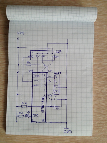
As such, there is no layout, because the circuit was finally formed at the time of assembly.
• VCC, GND, RX, TX (see datasheet on the controller) connect to the UART plug
• MOSI, MISO, GND, VCC, SCK, RST - to connect to the programmer connector, RST through 10 kOhm to VCC.
• Connect a debugging LED to pin 12 (PB0) of the controller; let its other output to VCC through a 200 Ohm resistor.
• Connect one pin of the button to the pin 6 (INT0) of the controller, the second to put on GND. To remove the “bounce” of pressing the button, it is desirable to connect a container in parallel with it. I connected 0.1 microfarad, because it was just such a capacitor that I had available, but it could be more. Without capacity, when pressed, several successive clicks will be generated. On leg 6, you also need to connect VCC through a 10 kΩ resistor.
After connecting the ISP and the LED, you can immediately check the performance of the circuit by flashing it with the proto / ledblink project from the repository.
To compile the schema, you need to run the command make flash. For firmware, you need a programmer driver and the avrdude utility. On the poppy just put the package CrossPack. You may also have to change some settings in the Makefile, for example, the usbtiny programmer on your model.
The performance of the UART can be checked by flashing the controller firmware from here www.getchip.net/posts/078-proverka-modulya-uart-attiny2313-testovaya-proshivka
In the github repository, see it in proto / uart_test. Run the write-fuses.sh script to flash the fuse bits, and then write_flash.sh to flash the firmware. We connect the board to the FTDI cable:
VCC -- VCC GND -- GND RX -- TX TX -- RX If everything works as it should, go to the project uart_attiny2313. The firmware works according to this principle - when a low signal arrives at INT0, an interrupt is created that wakes the controller from sleep, and the fire_keypress function is started. In this function, a combination of SHIFT + F10 characters is sent to the UART and the LED turns on / off.
If pressing the button in the terminal displays the desired combination of characters (in my case it is FE 02 02 42 FE 00, see the modem datasheet), this means that you can connect the board to the modem. The wiring is the same as when you connect the modem to the cable.
Next, connect to the appropriate power connectors and power button.

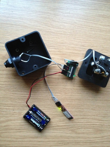
It now remains to place everything in the case.

Voila! Doomsday Button is ready! Now by clicking on it, events will be created - SHIFT-F10, which corresponds to the project build command in the Idea IDE.
Finally, the video, how it works.
www.youtube.com/watch?v=JafRsrstjKw
Source: https://habr.com/ru/post/151242/
All Articles