Simulator for testing software APCS: Example
 During the time that has passed since the publication of the first article on habrahabr, there was a desire to share with the community some thoughts, as well as to describe in more detail the process of creating a software simulator of the equipment being automated. Wishing to familiarize with the previous text, I ask here - the Simulator for software testing .
Now on the project site posted the full version of the program. After some reflection, I came to the conclusion that it would not be possible to develop this craft before a commercial product. I would be happy to receive feedback from colleagues in the shop, if someone comes in handy.
The task, which was chosen as an example, relates more to signal processing than to an automated process control system, and has absolutely no practical sense. This was done intentionally, in order not to distract the reader with unnecessary details of the subject area and increase visibility (everyone likes graphics).
')
Introduction
Almost in each article about TDD (Test-driven development) or Unit testing which I read, the expediency of spending the time allotted for a project to create tests was discussed. In the case of a simulator for testing software for an automated process control system, everything is somewhat more complicated, since it is up to some institute or very serious specialists to create a completely reliable model of a dynamic production process.
For myself, I chose a certain facet of the credibility of the model, after which the time spent on its creation does not justify itself. Frankly, there is a very lack of knowledge of technology, physics and mathematics, so I usually limit myself to simulating the operation of equipment and make a simple change of the physical parameter over time to check the automated functions and regulation.
It is human nature to make mistakes, so even when using the simplest model, a lot of errors pop up. In addition, it is worthwhile to “play around” with the system for a while and start asking questions that you would have thought about only at the stage of Poland.
In any case, for all the work, I have never regretted the time spent creating a simulator, since it is much more convenient than huge tables for monitoring and modifying variables. Even when I arrive at the site, I often use it for debugging. You can switch the entire system to a virtual model at any time and calmly, without nerves, do your work.
Task
The example that I will demonstrate is inspired by the pitiful remnants of electrical engineering knowledge that have been preserved from the university. Probably, many people remember the AC voltage converter circuit with a full diode bridge and a filter on a capacitor (the picture is taken from the link www.cqham.ru/pow2_15.htm ):
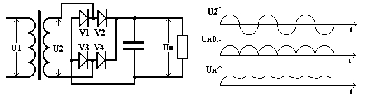
From the graphs it is clear that the bridge circuit converts the alternating voltage into a pulsating one, passing each half-period of the sinusoid through different valves, after which the capacitor smoothes the pulsation.
Let's try to create a model of the behavior of this scheme at the level of signal conversion.
Decision
After starting “Process Simulator” you can immediately start creating variables (Item-> Items Dictionary).
Items Dictionary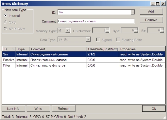
Create three internal variables:
- “Sin” - original sine wave
- “Positive” - value after conversion to a pulsating signal
- “Filter” - the result after the smoothing filter
Internal variables are designed to relate simulation objects to each other. A little later, I will explain how the simulator communicates with the outside world (PLC or other software).
Creating simulation objects is done with the help of a manager (Simulation-> Simulation Objects).
Simulation Objects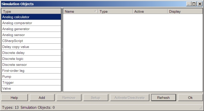
The first thing we need is the original sinusoidal signal. Create an object - “Analog generator” and tune it to the variable “Sin”.
Analog generator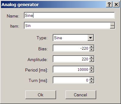
To implement the user interface, you need to create a screen (Visualization-> Add Screen) on which we will display the objects we created (Visualization-> Add ViewControl).
Viewcontrols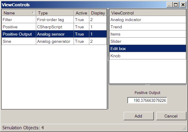
Each type of object has a number of ways to display. When you click the “Add” button, the selected display type is placed on the current screen, which we have already created. In order to change the position on the screen, you need to go to design mode (Visualization-> Design Mode) and drag the display with the mouse. If the display supports resizing, this can also be done in design mode.
Now it is necessary to convert a sinusoidal signal into a pulsating one. To do this, you can create an object that allows you to write scripts in C # - “CSharpScript”.
CSharpScript with script text
The script is more than primitive and does not need comments, except that our variables “Sin” and “Positive” are addressed through their aliases “var0” and “var1”, which are C # objects and must be declared in advance (Items ±) .
I will dwell on the type of this object. Using the standard functions of the .Net platform, the script we wrote is compiled into MSIL, so the execution speed is quite good. The frequency of running the script can be adjusted (Trigger Time). Errors at compile time will not allow to create an object. If errors occur at the execution stage or the execution time exceeds the allowable (Watchdog), the object will be deactivated and the error text will be written to the log. By the way, you can activate or deactivate an object of any type at any time, through the manager (Simulation-> Simulation Objects-> Activate / Deactivate) or through the context menu for displaying an object on the screen.
The final stage is filtering. To do this, create a “First-order lag” object with the input variable “Positive” and the output “Filter”.
First-order lag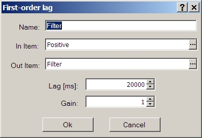
Result
After adding some auxiliary objects and placing the mappings on the screen, we get the following result:
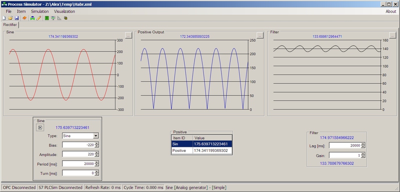
Now you can, for example, change the signal amplitude, period or other parameters and immediately see the changes.
Project saved in XML format
<ProcessSimulator WindowState="Normal" Top="152" Left="272" Height="703" Width="1463" Split="354"> <Items OPC_Host="" OPC_Server="" UseAccessPath="False" Separator="." IgnoreRoot="False" UpdateRate="0" UseASyncWrite="False" ReducedOPCItemIDs="False" S7PLCSim="False" S7ProSimInstance="1"> <Item Type="Internal" DataType="System.Double" Value="-76.1457525570486" ID="Sin" Comment=" " /> <Item Type="Internal" DataType="System.Double" Value="77.117550442077" ID="Positive" Comment=" " /> <Item Type="Internal" DataType="System.Double" Value="152.754176188765" ID="Filter" Comment=" " /> </Items> <SimulationObjects RefreshRate="0"> <SimulationObject Name="Filter" Active="True" Type="First-order lag" InValueItemID="Positive" OutValueItemID="Filter" LagMS="20000" Gain="1" /> <SimulationObject Name="Positive" Active="True" Type="CSharpScript" Watchdog="1000" TriggerTime="1"> <ItemIDs> <Var Value="Sin" /> <Var Value="Positive" /> </ItemIDs> <Script><![CDATA[if((double)var0 >= 0.0D) { var1 = (double)var0; } else { var1 = -(double)var0; }]]></Script> </SimulationObject> <SimulationObject Name="Positive Output" Active="True" Type="Analog sensor" RawValueItemID="" PhysicalValueItemID="Positive" MaxPhysicalValue="220" MinPhysicalValue="-220" MaxRawValue="27648" MinRawValue="0" Units="" /> <SimulationObject Name="Sine" Active="True" Type="Analog generator" ValueItemID="Sin" Signal="Sine" Bias="-220" Amplitude="220" Period="20000" Turn="0" /> </SimulationObjects> <Screens> <Screen Name="Rectifier" Open="true"> <ViewControl SimulationObject="Positive" Type="Items" X="615" Y="370" Width="230" Height="96" FirstColumnWidth="78" /> <ViewControl SimulationObject="Positive Output" Type="Trend" X="481" Y="0" Width="481" Height="324" UpdateRate="100" TimeFrame="1" Color="FF0000C0" /> <ViewControl SimulationObject="Filter" Type="Trend" X="966" Y="0" Width="481" Height="324" UpdateRate="100" TimeFrame="1" Color="FF000000" /> <ViewControl SimulationObject="Filter" Type="Simple" X="1110" Y="369" /> <ViewControl SimulationObject="Sine" Type="Trend" X="0" Y="0" Width="481" Height="324" UpdateRate="100" TimeFrame="1" Color="FFFF0000" /> <ViewControl SimulationObject="Sine" Type="Simple" X="112" Y="324" /> </Screen> </Screens> </ProcessSimulator> Communication with the outside world
Prehistory
When, I just started to engage in this project had to solve several dilemmas. First of all, the idea to create a simulator to use some kind of SCADA package appeared. Thus, the main problem of communications went away. Available at that time, for me, Siemens WinCC 6.2, has many drivers, including OPC and S7-PLCSim, which were needed. A little later, it turned out that it was impossible to implement what I had in mind on pure WinCC. Everything rested on the control of time, for example, the valve stroke from open to closed state. The next thought was to use WinCC as a container for the operation of .Net elements (.Net controls) in which to implement the simulation.
Maybe it's in crooked hands, but I did not manage to make the .Net element work in WinCC normally. The Internet did not help, so I decided to abandon this venture. Maybe the latest version of WinCC 7 is working, did not figure out.
After it became possible to use the ready OPC client library, I decided to write my own bike, to which I then added internal variables, connection with S7-PLCSim, and finally, the OPC server functionality to access all variables from the outside.
In the above example, only internal variables are used. Of course, this does not make sense, since the main idea of the simulator is to imitate work with real equipment for the PLC program.
If Siemens SIMATIC S7-PLCSim (V5.4 + SP4) is installed on the computer where the simulator is running, you can easily organize the recording of the result of our conversion of a sine wave to any (valid) PLC simulator memory.
First you need to connect (Items-> Connect S7 PLCSim). In the instance selection window, you can select a number from 1 to 8. This is the instance number of the S7-PLCSim (written in the window title) to which we want to connect. The latest version allows you to run eight instances simultaneously on one machine.
Create a new variable “FilterS7” with S7 PLCSim type and specify the address, for example, MD0 (Memory Type = M; Data Type = S7_DoubleWord; Byte = 0; Floating Point = true). Now it is enough to change the variable “Filter” to “FilterS7” in the objects.
With the connection via OPC everything is in the same order. Connect to an external server (Items-> Connect OPC), create variables that are available on the server, and use them in the simulation objects.
It must be borne in mind that, unlike internal variables, the S7 PLCSim and OPC variables are not always readable and writeable. For example, nothing can be written to the Q area of the PLC simulator, since this is the output area.
The last thing I would like to mention is that the simulator provides access to all its variables as an OPC server. All variables are visible under their own names and are available to any OPC client, for example, MatrikonOPC Explorer.
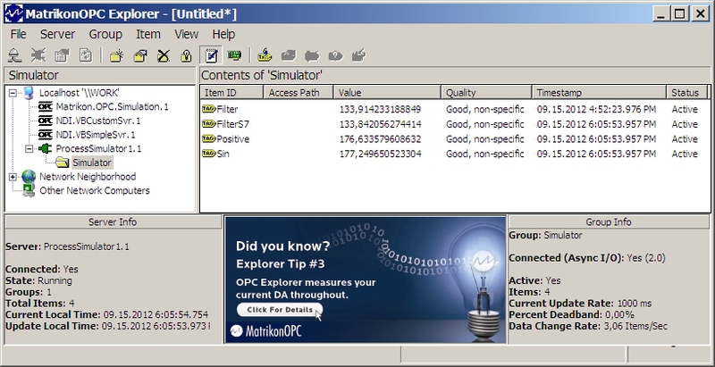
This functionality can be used, for example, to link S7PLCSim with SCADA or another package that supports OPC. Of course, beforehand, all variables must be added to Process Simulator.
Conclusion
I managed to make a tool that really helps me in my work. Perhaps it will be useful to someone else, I will be happy for reviews and even bug report :). If you are missing something, write. Perhaps, in the intervals between endless trips, I will have time to slightly expand the library of objects available in the program.
Source: https://habr.com/ru/post/151125/
All Articles