Raspberry Pi and Blue Electrical Tape

Good day, Habr!
In this topic, I want to tell you how to bring the Raspberry Pi into a usable form.
It all started with the fact that I received a long-awaited package with a Raspberry Pi board, but I was somewhat disappointed with some design features of this board. The desire to by all means make the board exactly the size of a bank card (a purely marketing move) led to the fact that there are no mounting holes on the board, the connectors are not located in the most convenient way, and the USB and Ethernet connectors are not at the same level, but in different planes. As a result, when working with the board on the table, you need to decompose: the board itself, the power adapter, a USB hub (if we want to connect anything other than a mouse and keyboard to the Raspberry Pi), and a bunch of wires that are always trying to slide, dragging along all this pile of iron.
')
About that, I found a way out of the situation, read under the cut (a lot of pictures!).
By the way, I had an old DVD player (yes, yes, it was on such devices that people watched movies in antiquity, before the era of torrents), and I decided to use it (or rather, its case and power source) as a platform for a device based on Raspberry Pi boards.
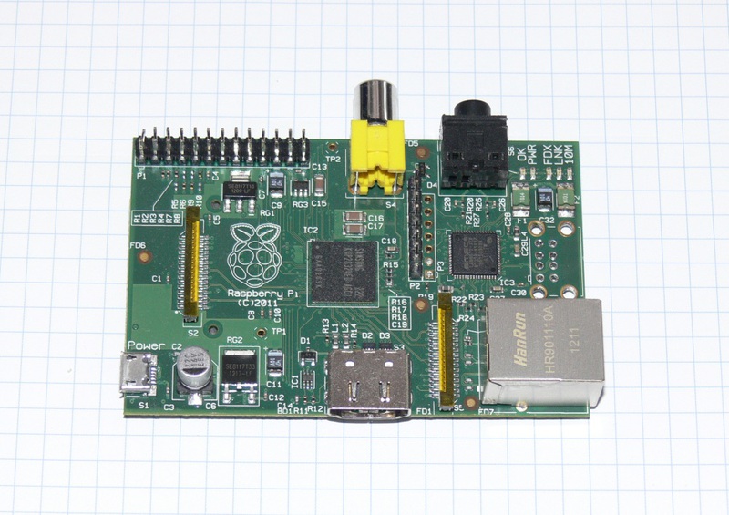
So, we have a Raspberry Pi board:
and Sony NS718 player:

Player outside

Player inside
Remove from the player everything except the power source. Now we need to install the necessary boards in the case, namely: a Raspberry Pi board and a USB hub with 7 ports (maybe there are not so many ports, but the stock does not pull the pocket).
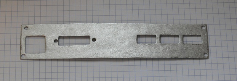
Enclosure and mounting plate
We will need to remake the back panel of the player in such a way as to bring all the connectors to it. To do this, we take the Dremel and cut a hole in the rear panel of the appropriate size. We make a metal plate with holes for the connectors we need. For a start, I decided to limit myself to three USB ports, a DVI connector and an Ethernet connector.
In the same case, in addition to the Raspberry Pi, there will be a USB hub. So, take the old USB hub:
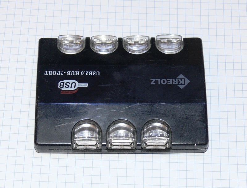
and extract from it a fee:

Now we need to fix all this. We mark and cut out a plate made of transparent plastic (it is possible, of course, from opaque, but which one it was):

Since the Raspberry Pi does not have mounting holes, the board will be fixed by “sticking” to the edges with screws located along the perimeter.
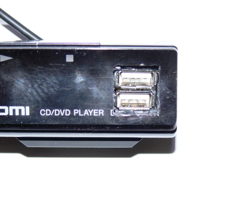
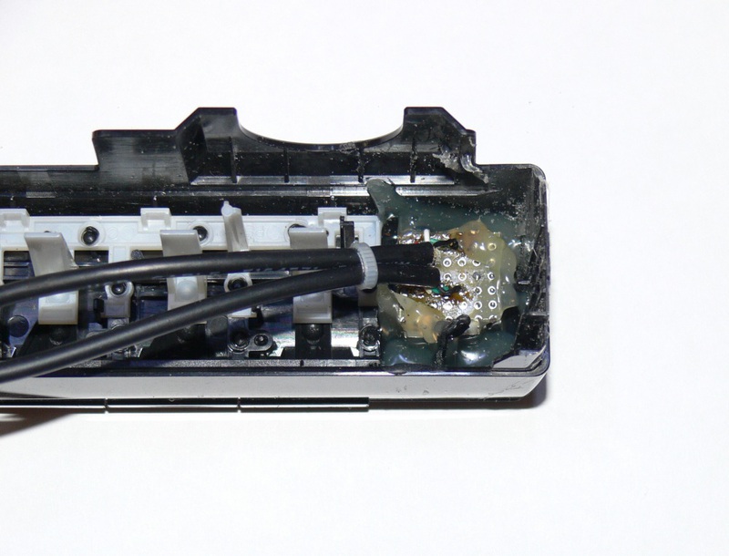
It is also a good idea to have USB connectors not only at the back, but also at the front. So, we saw a hole in the front panel under the two USB connectors, we mount the connectors on a small prototyping board and solder the “tails” to them, which will be inserted into the hub. Glue the board in place with hot glue.
We also seal the opening of the DVD drive on the front panel, for this we use the “native” cover from the DVD drive.
The first thing I would like to do is get rid of the bulging USB connector. We remove it and solder the IDC 5x2 connector in its place, as on ordinary motherboards (do not try to do it yourself if you do not have enough experience in assembling and dismantling electronic components!). We delete one contact from the connector, as it should be at the standard USB connection on the mat. board:

Board with dismounted USB connector

Wires and adapters
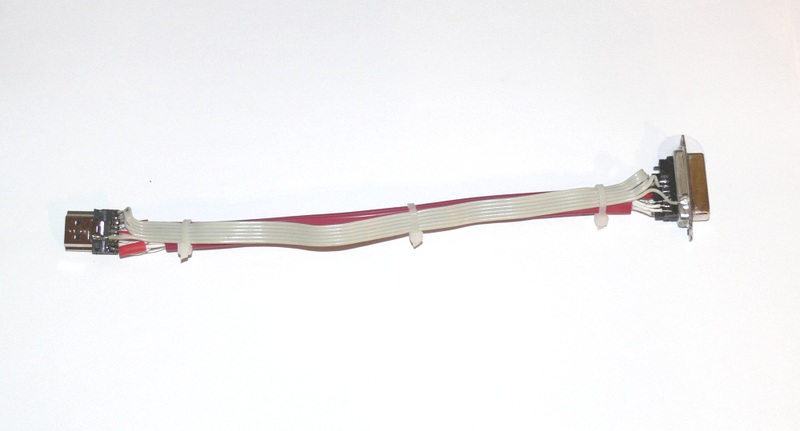
Now it was the turn to do all the internal wiring. Making an adapter HDMI-DVI. The signals in this interface are transmitted over four shielded differential pairs, I used a piece of SATA cable as such pairs.
We remove the connectors from a standard HDMI-DVI adapter:

The desoldering table and the photo of the resulting adapter are shown below:
Making internal USB cable. On the one hand, it has an IDC connector, which we plug into the Raspberry Pi, on the other hand, it has a regular miniUSB connector, which will be inserted into a USB hub. And here for the first time Blue Insulating Tape will help us!

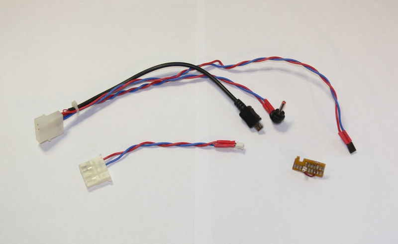
We make adapters with power connectors and a small scarf with LED for power indication. Glue the scarf to the front panel.
Power supply
The player’s power supply is turned on with a button on the front panel, and the signal from the button enters the player’s controller and it turns the power on / off. In order for this to work, there are non-disconnectable voltages in the power supply. We now have such difficulties for nothing, so we put a simple key switch into the case (yes, by the way, it has a neon!).
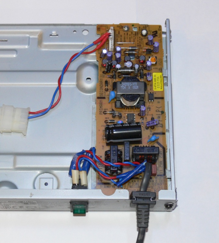
And again the irreplaceable Blue Insulating Tape helped us!
The source enable signal (the one that the player controller controlled) is soldered to with a non-disconnecting source of +5 V.
Final assembly and verification
When assembled, the whole structure looks like this:
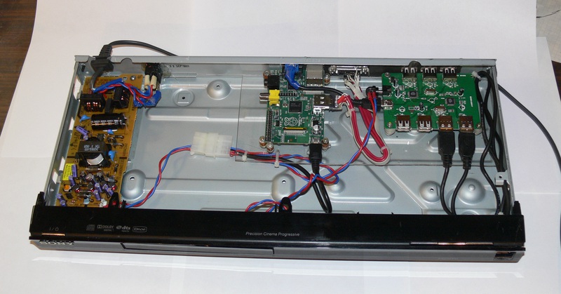
Front view
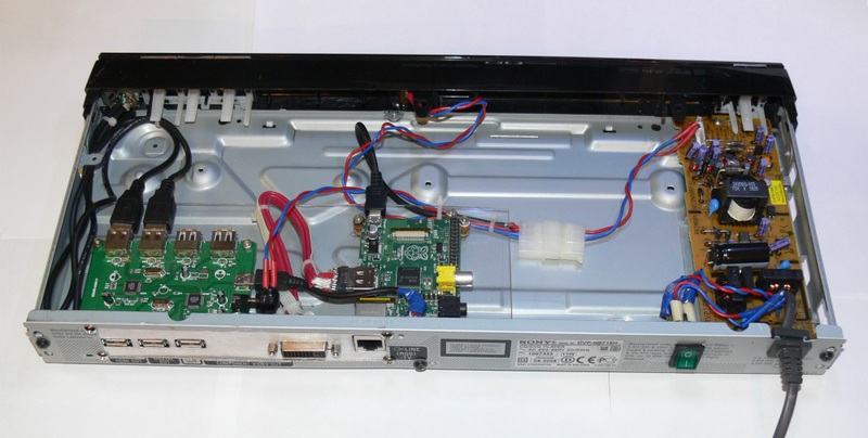
Back view
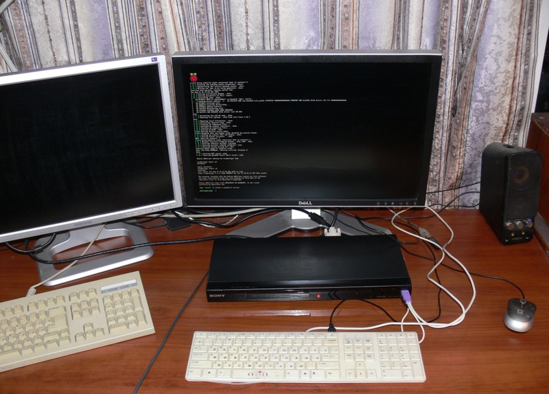
Install an SD card with the operating system (Debian Wheezy) in the Raspberry Pi, close the top cover, connect the monitor, mouse and keyboard, turn on ... Here it is, the moment of truth:
Project's budget
Raspberry Pi motherboard with delivery (via Farnell) - 2016 p.
Sony NS718 player (purchased in markdown) - 500 p.
DVI-HDMI adapter - 389 p.
SD card (8 GB) - 370 p.
USB hub for 7 ports - lying like trash
A bunch of USB cables - also wallowing like trash.
Also involved in the project were various screws, flaps, wiring, hot melt glue and Blue Electrical Tape.
Future plans
Future plans are as follows:
- Install the hard disk into the case. This will require installing a USB-SATA interface board and replacing the power supply (this one will not pull the power of the HDD).
- Make normal power management. The device will be turned on by a button on the front panel, and turned off by software (like this: sudo shutdown -h now).
- Install the board with the indicator from the source player and connect it to the Raspberry Pi. The indicator can display various messages.

On the same board is an infrared sensor, and it will be possible to implement control from the remote control. - Display the audio connector on the back panel.
But that's another story.
Source: https://habr.com/ru/post/151113/
All Articles