Using Direct2D technology to create WinRT components
 This article continues our series of stories in which we share our experience in developing visual WinRT controls in the style of the Windows 8 UI.
Last time we gave the basic steps needed to create your WinRT control and SDK for it, and now we’ll talk about using Direct2D technology to create visual effects in your WinRT component.
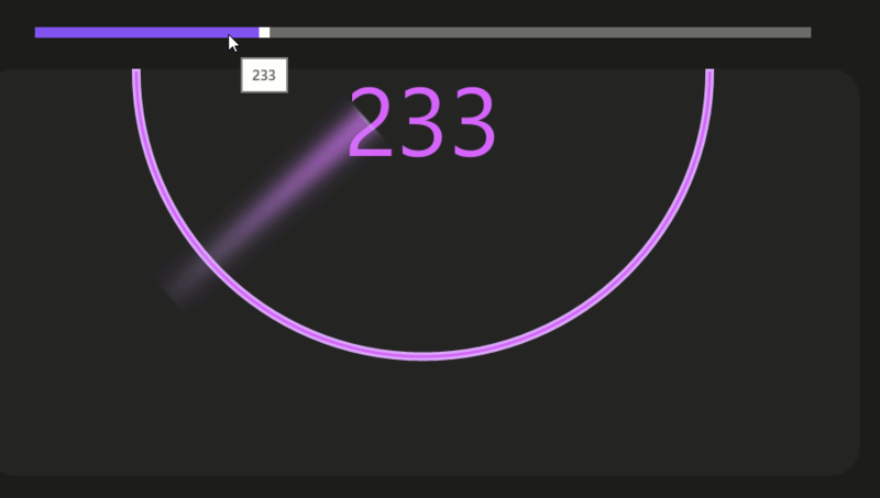
In this article we will look at the process of creating a circular gauge aka indicator (gauge control), whose arrow will blur when moving.
')
Note: You can download the full code for this project at the following link: go.devexpress.com/Habr_WinRTSample.aspx
What is Direct2D?
Direct2D technology is a hardware accelerated API for 2D graphics that delivers high performance and high quality display of 2D geometry, bitmap images and text.
The Direct2D API was developed by Microsoft to create applications running on the Windows operating system and to interact with existing code that uses GDI, GDI +, or Direct3D.
When is it necessary to use Direct2D in my applications?
A typical example is the optimization of the performance of applications in which a large number of graphic elements are drawn (for example, this is necessary when creating graphs with a large amount of data, maps, and various indicators-gages).
You can learn more about Direct2D and its application features in the corresponding MSDN section .
System requirements
To develop applications in the style of Windows 8 UI (METRO), you will need Windows 8 and Visual Studio 2012. For more details, see our previous article .
Creating a C ++ library with a component using Direct2D
To use Direct2D in your application, you need to write a WinRT component in C ++.
To do this, follow these steps:
- Start Visual Studio 2012 (if you ever close it at all :-))
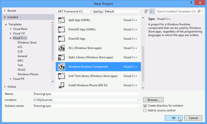
- Create a new Visual C ++ project of type Windows Runtime Component
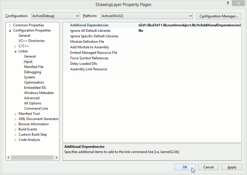
This library will contain the declaration implementation and the implementation of several interfaces designed for drawing using Direct2D technology. - Then it is necessary in the properties of our C ++ project to add links to the Direct2D libraries: d2d1.lib and d3d11.lib.
- Next, you need to write an implementation implementation of our component using Direct2D.
First, we create a static DrawingFactory class with one single method, CreateRenderer , which will initialize the DirectX library, create and return an instance of the Renderer class:public ref class DrawingFactory sealed { public: static IRenderer^ CreateRenderer(); };
Secondly, we describe the main interface IRenderer , which will contain the following methods and properties:
- Reset method, designed to recreate the surface for drawing, in our case, it is an ImageBrush with the dimensions that were transferred. In what follows, we will assign the resulting ImageBrush to any element in the visual tree of our WinRT component;
- the TargetBrush property, which will return the created brush in the Reset method and must contain the result of the drawing;
- properties EnableMotionBlur , MotionBlurAngle , MotionBlurDeviation , which serve to enable and adjust the blur effect when rendering primitives;
- methods CreateGeometry , DrawGeometry , FillGeometry , designed to create and draw geometry;
- In addition, the interface in question contains some more simple and clear methods and properties, such as BeginDraw , EndDraw , Clear , TargetWidth and TargetHeight .public interface class IRenderer { property int TargetWidth { int get(); } property int TargetHeight { int get(); } property ImageBrush^ TargetBrush { ImageBrush^ get(); } property bool EnableMotionBlur { bool get(); void set(bool value); } property float MotionBlurAngle { float get(); void set(float value); } property float MotionBlurDeviation { float get(); void set(float value); } void Reset(int width, int height); void BeginDraw(); void EndDraw(); void Clear(Color color); IShapeGeometry^ CreateGeometry(); void DrawGeometry(IShapeGeometry^ geometry, Color color, float width); void FillGeometry(IShapeGeometry^ geometry, Color color); };
And now tell you about how we will do the blur effect. With Direct2D, this problem is solved very simply. In the Reset method, you need to create a standard DirectionalBlur effect, and a temporary bitmap ( m_inputSource ), into which we will draw and use it as a source for the previously created effect:void Renderer::Reset(int width, int height) { D3D_FEATURE_LEVEL featureLevels[] = { D3D_FEATURE_LEVEL_11_1, D3D_FEATURE_LEVEL_11_0, D3D_FEATURE_LEVEL_10_1, D3D_FEATURE_LEVEL_10_0, D3D_FEATURE_LEVEL_9_3, D3D_FEATURE_LEVEL_9_2, D3D_FEATURE_LEVEL_9_1 }; ThrowIfFailed(D3D11CreateDevice(nullptr, D3D_DRIVER_TYPE_HARDWARE, 0, D3D11_CREATE_DEVICE_BGRA_SUPPORT, featureLevels, ARRAYSIZE(featureLevels), D3D11_SDK_VERSION, &m_d3dDevice, NULL, &m_d3dContext)); ThrowIfFailed(m_d3dDevice.As(&m_dxgiDevice)); ThrowIfFailed(m_d2dFactory->CreateDevice(m_dxgiDevice.Get(), &m_d2dDevice)); ThrowIfFailed(m_d2dDevice->CreateDeviceContext(D2D1_DEVICE_CONTEXT_OPTIONS_NONE, &m_d2dContext)); m_imageSource = ref new SurfaceImageSource(width, height, false); IInspectable* inspectable = (IInspectable*) reinterpret_cast<IInspectable*>(m_imageSource); ThrowIfFailed(inspectable->QueryInterface(__uuidof(ISurfaceImageSourceNative), (void**)&m_imageSourceNative)); ThrowIfFailed(m_imageSourceNative->SetDevice(m_dxgiDevice.Get())); m_imageBrush = ref new ImageBrush(); m_imageBrush->ImageSource = m_imageSource; m_targetWidth = width; m_targetHeight = height; ThrowIfFailed(m_d2dContext->CreateEffect(CLSID_D2D1DirectionalBlur, &m_blurEffect)); m_d2dContext->CreateBitmap(D2D1::SizeU(m_targetWidth, m_targetHeight), nullptr, 0, D2D1::BitmapProperties1(D2D1_BITMAP_OPTIONS_TARGET,D2D1::PixelFormat(DXGI_FORMAT_B8G8R8A8_UNORM, D2D1_ALPHA_MODE_PREMULTIPLIED)), &m_inputSource); m_blurEffect->SetInput(0, m_inputSource.Get()); }
Then in the BeginDraw method as the drawing surface, use the intermediate bit__inputSource, and when the drawing is completed, use the EndDraw method to set the TargetBrush surface and, depending on the value of the EnableMotionBlur property, draw either an effect or an intermediate bitmap.void Renderer::BeginDraw() { if (!m_drawingInProcess && (m_d2dContext.Get() != NULL)) { m_d2dContext->BeginDraw(); m_d2dContext->SetTarget(m_inputSource.Get()); m_drawingInProcess = true; } } void Renderer::EndDraw() { if (m_drawingInProcess) { m_d2dContext->EndDraw(); ComPtr<ID2D1Bitmap1> bitmap; PrepareSurface(&bitmap); m_d2dContext->SetTarget(bitmap.Get()); m_d2dContext->BeginDraw(); m_d2dContext->Clear(D2D1::ColorF(0.0f, 0.0f, 0.0f, 0.0f)); if (m_motionBlurEnabled) { m_blurEffect->SetValue(D2D1_DIRECTIONALBLUR_PROP_STANDARD_DEVIATION, m_motionBlurDeviation); m_blurEffect->SetValue(D2D1_DIRECTIONALBLUR_PROP_ANGLE, m_motionBlurAngle); m_d2dContext->DrawImage(m_blurEffect.Get()); } else m_d2dContext->DrawImage(m_inputSource.Get()); m_d2dContext->EndDraw(); m_d2dContext->SetTarget(NULL); m_imageSourceNative->EndDraw(); m_drawingInProcess = false; } }
Creating a C # library containing the WinRT component
In the next step, we need to add another project to our solution - this time C #. This project is a library containing a WinRT component that will operate on a previously written C ++ library.

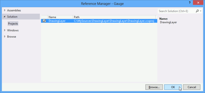
For this project you need to add links to the previously created C ++ assembly:
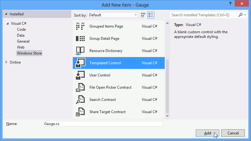
This library will contain WinRT Gauge itself. To include it in our build, add a new Templated Control:
All visual elements, except for the arrow, will be rendered using standard WinRT tools, namely, we will set in the template:
<Style TargetType="local:Gauge"> <Setter Property="Template"> <Setter.Value> <ControlTemplate TargetType="local:Gauge"> <Grid> <Grid Margin="0,0,0,0"> <Rectangle Fill="#FF252525" RadiusX="30" RadiusY="30"/> <Path Stretch="Uniform" VerticalAlignment="Top" HorizontalAlignment="Center" Stroke="#FFDAA5F8" Fill="#FFD365F8" StrokeThickness="3" StrokeStartLineCap="Square" StrokeEndLineCap="Square" Margin="150,0,150,0"> <Path.Data> <PathGeometry> <PathGeometry.Figures> <PathFigure StartPoint="0,0"> <PathFigure.Segments> <LineSegment Point="0.1,0"/> <ArcSegment Point="10.1,0" Size="5,5" RotationAngle="180" IsLargeArc="False" SweepDirection="Counterclockwise"/> <LineSegment Point="10.2,0"/> <ArcSegment Point="0,0" Size="5.1,5.1" RotationAngle="180" IsLargeArc="False" SweepDirection="Clockwise"/> </PathFigure.Segments> </PathFigure> </PathGeometry.Figures> </PathGeometry> </Path.Data> </Path> <TextBlock Text="{Binding Value, RelativeSource={RelativeSource Mode=TemplatedParent}}" FontSize="100" Foreground="#FFD365F8" VerticalAlignment="Top" HorizontalAlignment="Center"/> <Border x:Name="RendererSurface"/> </Grid> </Grid> </ControlTemplate> </Setter.Value> </Setter> </Style> In the visual representation of the component in question, there is an empty Border named RendererSurface . We will get this element in the OnApplyTemplate method and save it to a class variable so that we can assign the Brush from the renderer to its Background property.
protected override void OnApplyTemplate() { base.OnApplyTemplate(); rendererSurface = (Border)GetTemplateChild("RendererSurface"); } In the constructor of our class, we must create an IRenderer using the DrawingFactory and also subscribe to the SizeChanged event. At this event, we will call the IRenderer.Reset method, so that the size of the brush, in which the drawing will be performed, corresponds to the size of the component. We also subscribe to the static CompositionTarget.Rendering event - on the handler of this event we will draw our arrow.
public Gauge() { renderer = DrawingFactory.CreateRenderer(); DataContext = this; this.DefaultStyleKey = typeof(Gauge); arrowStrokeColor = ColorHelper.FromArgb(0xFF, 0xD3, 0xAA, 0xF8); arrowFillColor = ColorHelper.FromArgb(0xFF, 0xD3, 0x65, 0xF8); this.SizeChanged += Gauge_SizeChanged; CompositionTarget.Rendering += CompositionTarget_Rendering; } void Gauge_SizeChanged(object sender, SizeChangedEventArgs e) { renderer.Reset((int)e.NewSize.Width, (int)e.NewSize.Height); rendererSurface.Background = renderer.TargetBrush; } void CompositionTarget_Rendering(object sender, object e) { Render(); } Now we just have to add one Value dependency property and draw the arrow geometry:
static readonly DependencyProperty ValueProperty = DependencyProperty.Register("Value", typeof(double), typeof(Gauge), new PropertyMetadata(0.0, ValuePropertyChanged)); public double Value { get { return (double)GetValue(ValueProperty); } set { SetValue(ValueProperty, value); } } public static void ValuePropertyChanged(DependencyObject d, DependencyPropertyChangedEventArgs e) { Gauge gauge = d as Gauge; if (gauge != null) gauge.renderer.EnableMotionBlur = true; } void Render() { double angle = Math.PI * Value / 1000 - Math.PI / 2.0; IShapeGeometry geometry = CreateArrowGeometry(angle); renderer.BeginDraw(); renderer.MotionBlurAngle = (float)(angle / Math.PI * 180); renderer.MotionBlurDeviation = 5.0f; renderer.Clear(Colors.Transparent); renderer.FillGeometry(arrow, ColorHelper.FromArgb(0xFF, 0xD3, 0x65, 0xF8)); renderer.DrawGeometry(arrow, ColorHelper.FromArgb(0xFF, 0xD3, 0xAA, 0xF8), 3.0f); renderer.EndDraw(); if (renderer.EnableMotionBlur) renderer.EnableMotionBlur = false; } That's all. Our component is ready, and now we can use it in a real application.
Using WinRT component Gauge
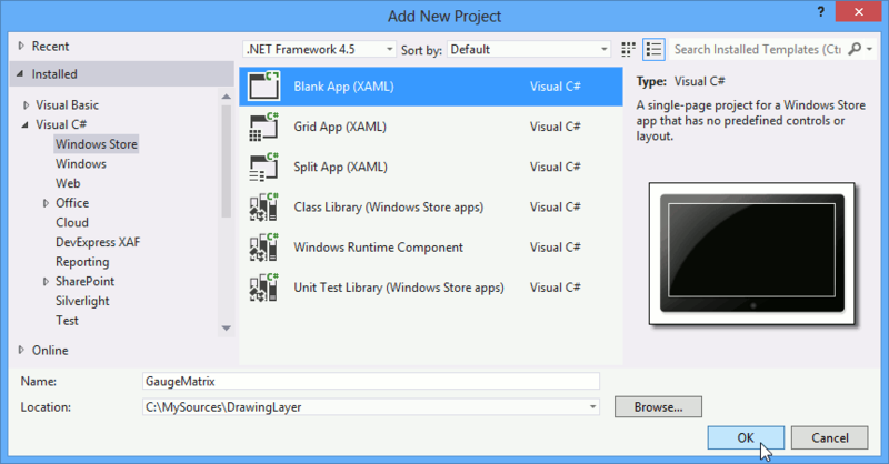
In order to demonstrate the performance of our component, add another project to our solution. Let it be a template Blank App (XAML) . Let's call our test project GaugeMatrix :
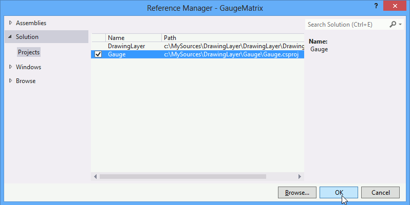
Then in this project we will add links to the Gauge and DrawingLayer projects created earlier:
Next, add a Grid to MainPage.xaml and create two rows and two columns in it.
<Grid.ColumnDefinitions> <ColumnDefinition Width="*"/> <ColumnDefinition Width="*"/> </Grid.ColumnDefinitions> <Grid.RowDefinitions> <RowDefinition Height="*"/> <RowDefinition Height="*"/> </Grid.RowDefinitions> After that, in each cell we put our Gauge component, as well as the Slider to dynamically change the value displayed with the arrow on the Gauge control:
<Grid Grid.Column="0" Grid.Row="0" Margin="30"> <Grid.RowDefinitions> <RowDefinition Height="Auto"/> <RowDefinition Height="*"/> </Grid.RowDefinitions> <Slider Grid.Row="0" Name="ValueSlider1" Minimum="0" Maximum="1000" Value="0" Width="1000" Margin="50,0,50,0"/> <g:Gauge Grid.Row="1" Value="{Binding ElementName=ValueSlider1, Path=Value}"/> </Grid> We make the GaugeMatrix project a start- up, launch the application and ... everything, you managed to use drawing with Direct2D in your WinRT application! Congratulations!
Note: You can download the full code for this project at the following link: go.devexpress.com/Habr_WinRTSample.aspx
PS All those who want to ask us their questions about the development of components for WinRT, we will be happy to see on September 7 in Moscow on Windows 8 Camp ! If you are not able to attend this event, then follow the online broadcast!
Source: https://habr.com/ru/post/150618/
All Articles