For those who have MIMO passed by ...
Good day, Habr! Analyzing the topic of technology MIMO (Multiple input-multiple output), which is now used everywhere, I found how little material on this topic is presented in the domestic literature. Habr regularly read about 3 years and I did not see a full educational program on this issue here either. I will try to correct this situation. How IT works and why it is relevant today, as well as the history of the development of this technology. Anyone interested under the cat.
MIMO used to be represented only as a technology of diversity reception (we have one transmitting and N receiving antennas). Implementing this idea, several series of military tropospheric stations were released (maybe someone had to serve at such), and in principle at that stage, the cost of deploying additional antennas was justified.
The processing principle was simple as a shovel: in two receiving branches the signal-to-noise ratio was compared and, according to the assessment of this value, weighting factors were assigned to each processing branch, which played a role in the decision-making, roughly speaking, what was transmitted: 0 or 1. This simple system It was named the criterion for optimal weight addition (MRC).
')
Further more. In 1997, the Iranian-American Alamouti offers a novelty based on already known theses, calling it the space-time block code (STBC). After that, the shaft of publications on the topic of MIMO increases from year to year and the topic becomes very relevant against the background of the fact that the frequency and energy efficiency of communication systems has become more and more complicated (the most efficient signal-code structures have been thought out). And then it went further: space-time lattice coding , spatial multiplexing, as well as a large number of decoding algorithms from the simplest “maximum likelihood (ML- max likehood)” to spherical turbo decoding on the GPU, etc.
Passing the path from the transmitter (T) to the receiver (R), our radio wave attenuates (loses in the power industry), and how much it loses depends on whether there is a direct line of sight between our T and R. If it is, then the main blame for the loss lies on the loss of the distribution medium (path loss), if there is no direct visibility, then the most interesting begins. Facing various obstacles, the wave travels to its destination in several ways (multipath propagation) and, accordingly, each beam travels a different distance. At the reception, all of these rays can fold out of phase, which additionally reduces the signal intensity, which causes the signal level to constantly “float”. Therefore, in the area of uncertain reception, your cell phones cannot determine how many “signal sticks” to show.
All this mess is called fading . They can be different and can be described by different laws. In the presence of a permanent component (in the presence of a direct visibility), the Rice distribution will be suitable, and in its absence, Rayleigh (private version). I will not give formulas intentionally, they are big and scary.
k is the so-called complex channel transfer function (which determines its phase response and frequency response ), and is different for each time point for each of the received signals. The main highlight is precisely the fact that the signals for each of the receiving antennas pass through different paths .
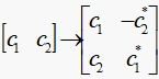
In accordance with the STBC method, the input data stream is divided into pairs [c1, c2], with, on the first half-clock interval, the symbol c1 is transmitted through the antenna T1 and the symbol c2 is transmitted through the antenna T2. On the second half-clock interval, the transmission order changes: through the antenna T1, the inversion of the c2 symbol is transmitted (indicated as (–c * 2) in the figure, and the symbol c1 is transmitted through the antenna of T2 (indicated in the figure as (c * 1). This algorithm is conveniently presented in As a matrix, where the line number will correspond to the transmitter number, and the column number is the half-cycle number (in the general case, the tact step) of the transfer. The " * " symbol, as many have already guessed, is a complex conjugate.
As a result, at the input we get 2 signals (multiplicative responses for the first and second cycles), after conducting a series of interesting mathematical transformations, we get the original signal, or rather a pair of these signals. Actually the whole trick is that each of these signals was transmitted 2 times .
Why is this possible? Because k is different for each ray , and the Alamouti matrix (picture above) is orthogonal .
I spend all my calculations and modeling in Matlab 'e because thisis the best environment in the world that is very convenient for such experiments.
Here is the actual piece for calculating the Alamouti curve:
This part is for the classic scheme:
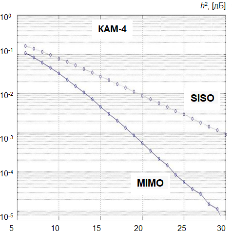
The graph shows that the gain for the error probability Rosh = 10 ^ (- 3) is approximately 12 [dB] . And this is just a huge amount.
Thanks to those who read it, I want to note that:
The rest is already about MIMO-OFDM and this is the topic of a separate article.
A little bit of history
In a large number of technologies that take place in today's telecommunications environment, "legs grow" from military developments . The technology of orthogonal frequency multiplexing (OFDM), for example, was proposed as early as the 80s by our American friends, but it was only recently realized because it is extremely demanding on the computational power of the system (the notorious FFT ).MIMO used to be represented only as a technology of diversity reception (we have one transmitting and N receiving antennas). Implementing this idea, several series of military tropospheric stations were released (maybe someone had to serve at such), and in principle at that stage, the cost of deploying additional antennas was justified.
The processing principle was simple as a shovel: in two receiving branches the signal-to-noise ratio was compared and, according to the assessment of this value, weighting factors were assigned to each processing branch, which played a role in the decision-making, roughly speaking, what was transmitted: 0 or 1. This simple system It was named the criterion for optimal weight addition (MRC).
')
Further more. In 1997, the Iranian-American Alamouti offers a novelty based on already known theses, calling it the space-time block code (STBC). After that, the shaft of publications on the topic of MIMO increases from year to year and the topic becomes very relevant against the background of the fact that the frequency and energy efficiency of communication systems has become more and more complicated (the most efficient signal-code structures have been thought out). And then it went further: space-time lattice coding , spatial multiplexing, as well as a large number of decoding algorithms from the simplest “maximum likelihood (ML- max likehood)” to spherical turbo decoding on the GPU, etc.
How it works
And a little more theoryRadio channels
In general, this classification is huge and its review is worthy of a separate article, but we will focus on only a few points.Passing the path from the transmitter (T) to the receiver (R), our radio wave attenuates (loses in the power industry), and how much it loses depends on whether there is a direct line of sight between our T and R. If it is, then the main blame for the loss lies on the loss of the distribution medium (path loss), if there is no direct visibility, then the most interesting begins. Facing various obstacles, the wave travels to its destination in several ways (multipath propagation) and, accordingly, each beam travels a different distance. At the reception, all of these rays can fold out of phase, which additionally reduces the signal intensity, which causes the signal level to constantly “float”. Therefore, in the area of uncertain reception, your cell phones cannot determine how many “signal sticks” to show.
All this mess is called fading . They can be different and can be described by different laws. In the presence of a permanent component (in the presence of a direct visibility), the Rice distribution will be suitable, and in its absence, Rayleigh (private version). I will not give formulas intentionally, they are big and scary.
MIMO here it is
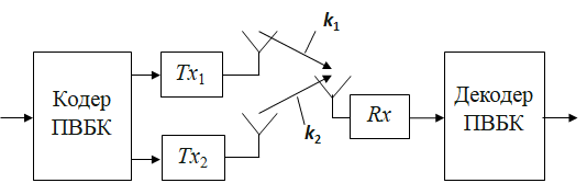
Analysis of how IT works will be carried out on the simplest example. We have 2 antennas in transmission and one in reception.k is the so-called complex channel transfer function (which determines its phase response and frequency response ), and is different for each time point for each of the received signals. The main highlight is precisely the fact that the signals for each of the receiving antennas pass through different paths .
In accordance with the STBC method, the input data stream is divided into pairs [c1, c2], with, on the first half-clock interval, the symbol c1 is transmitted through the antenna T1 and the symbol c2 is transmitted through the antenna T2. On the second half-clock interval, the transmission order changes: through the antenna T1, the inversion of the c2 symbol is transmitted (indicated as (–c * 2) in the figure, and the symbol c1 is transmitted through the antenna of T2 (indicated in the figure as (c * 1). This algorithm is conveniently presented in As a matrix, where the line number will correspond to the transmitter number, and the column number is the half-cycle number (in the general case, the tact step) of the transfer. The " * " symbol, as many have already guessed, is a complex conjugate.
As a result, at the input we get 2 signals (multiplicative responses for the first and second cycles), after conducting a series of interesting mathematical transformations, we get the original signal, or rather a pair of these signals. Actually the whole trick is that each of these signals was transmitted 2 times .
Why is this possible? Because k is different for each ray , and the Alamouti matrix (picture above) is orthogonal .
Practice
And now let's do a simulation and see the MIMO win before SISO (single in single out).I spend all my calculations and modeling in Matlab 'e because this
Here is the actual piece for calculating the Alamouti curve:
numOfBlk = 1e6; % qampoz = 4; % SNRdB = 6:1:40; % / linColor = 'b'; % 1 linSym = 'o'; % 2 errRate = zeros(size(SNRdB)); % % for i = 1 : length(SNRdB) txData = randint(numOfBlk*2,1,qampoz);% temp = reshape(txData,numOfBlk,2); % temp = qammod(temp,qampoz); % H = 1/sqrt(2) * (randn(numOfBlk,2) + sqrt(-1)*randn(numOfBlk,2)); % ( ) txMod(:,1) = H(:,1).* 1/sqrt(2).*temp(:,1) + H(:,2).* 1/sqrt(2).*temp(:,2) ; % txMod(:,2) = -H(:,1).*(1/sqrt(2).*temp(:,2)').' + H(:,2).*(1/sqrt(2).*temp(:,1)').' ; txMod = awgn(txMod,SNRdB(i),'measured'); temp(:,1) = sqrt(2)*(H(:,1)'.' .* txMod(:,1) + H(:,2) .* txMod(:,2)'.')./(abs(H(:,1)).^2 + abs(H(:,2)).^2); temp(:,2) = sqrt(2)*(H(:,2)'.' .* txMod(:,1) - H(:,1) .* txMod(:,2)'.')./(abs(H(:,1)).^2 + abs(H(:,2)).^2); rxData(:,1) = qamdemod(temp(:,1),qampoz); % rxData(:,2) = qamdemod(temp(:,2),qampoz); [numErr errRate(i)] = symerr(rxData,reshape(txData,numOfBlk,2)); % end This part is for the classic scheme:
%SISO for i = 1 : length(SNRdB) temp = qammod(txData,qampoz); H = 1/sqrt(2) * (randn(numOfBlk*2,1) + sqrt(-1)*randn(numOfBlk*2,1));% txMod = H.*temp; txMod = awgn(txMod,SNRdB(i),'measured'); temp = txMod./H; rxData = qamdemod(temp,qampoz); [numErr errRate(i)] = symerr(rxData,txData); end The graph shows that the gain for the error probability Rosh = 10 ^ (- 3) is approximately 12 [dB] . And this is just a huge amount.
As a conclusion
Thanks to those who read it, I want to note that:
- The single-frequency signal is good, but in the calculations I accepted the ideal version when the channel KPF is precisely known at the reception, but how to evaluate it in reality? This is where the OFDM signal is ideal in the structure of which you can embed pilot signals and use it to build a channel profile (learn the CPP for each subcarrier). By the way, they were used before MIMO (see DVB-T for example) to evaluate noise immunity.
- The model of the channel is chosen the easiest and far from the real
- The model of the signal is chosen the simplest, if you take the OFDM signal, then its formation itself is not an easy task + then there should be other conditions to the channel model (a frequency-selective channel is needed)
- PVBK is not the only and not the most efficient method used in MIMO technology, but the simplest and most easily implemented
- The gain for KAM-16.64 decreases with increasing positioning, it's all about energy (the reason is less Euclidean distance between the signal points)
The rest is already about MIMO-OFDM and this is the topic of a separate article.
Source: https://habr.com/ru/post/150225/
All Articles