Development of a particle system based on DirectX 9. Part II
This post is the 2nd and last part of an article about developing a particle system on DirectX 9. If you haven’t read the first part yet, I recommend reading it.
In this part of the article will be considered: working with sprites, vertex and pixel shaders, effects, post effects. In particular, for the implementation of the post-effect - reception of the render in the texture.
')
Sprites are a texture that moves around the screen and depicts an object or part of an object. Since the particles in our system are just points, superimposing various textures on them can visualize any object (for example, clouds). Since the sprite is a simple texture, you need to have a basic understanding of them.
The texture instead of pixels, as we used to, has texels. Direct3D uses a coordinate system for textures formed by the horizontal axis U and the vertical axis V.

Vertex shaders is a program that is created in a special language HLSL (or assembler), and is engaged in vertex conversion and lighting. In the vertex shader, we can take the position of the vertex and move it to a completely different place. The article vertex shader will also be used to generate texture coordinates.
They look like vertex shaders, but instead of them they are engaged in rasterization of the image. Such a shader transmits data about texture, color and many others, and on the basis of this, the shader is obliged to return the color of the pixel. We will use them for texturing.
Effects will include pixel and / or vertex shaders, and one or more render passes. Using them you can implement, for example, the effects of blur or glow.
Post effects differ from the usual ones in that they are applied to an already cut scene.
Before we apply the texture to the particles, we need to change the type we used to represent the vertices in the buffer to the following:
The values of u and v must be initialized to zero when created.
It is also necessary to change the flags when creating the buffer, and the description of the buffer:
Add the D3DFVF_TEX0 flag, indicating that we will store the texture coordinates. We also add a string to the vertex description.
And now it remains to load the texture and change the render state:
All states will not describe, information about them can be found on MSDN. I can only say that we will need some of them for effects.
Load the texture and set it from the file that will represent the particle.
Everything, now when you start the application, you will see textured particles instead of simple points, but we will go further and add a simple effect to the resulting image.
Result of visualization:
For the development of effects there is a great program from NVIDIA, it is called Fx Composer . Debugging shaders, shaders version 4, DIrect3D (9, 10) and OpenGL are supported. I highly recommend, but in this article this development environment will not be considered.
First, consider the basic structure of effects:
As you can see from the code, each of the shaders accepts and returns some value. The vertex shader must return the coordinates of the vertex, and the pixel color of the pixel being processed.
The effect is divided into several techniques . Each of the techniques can represent their own way of applying effects, or a different effect altogether.
Each technique has one or more visualization passes.
It is time to write your simple effect, which, for example, will paint the particles red:
The code for this effect differs little from the basic structure previously considered by us. We have added only mixing with red color by multiplication method (multiply blend). Here's what we got:
Not bad, but you can change the blend mode to another, and make blending not with one color, but with the whole texture.
In order for us to get the right mix of particle visualization and texture, we need to use a technique called Render Target (visualization target). The essence of the technique is simple, we visualize our scene in texture, and then apply effects to the already rasterized image.
Here is the full effect code of this effect:
As you noticed, there is another stage of visualization. At the first stage, we visualize particles as they are. And the visualization we will need to perform in texture. And already in the second pass of the visualization, we impose another texture on the image using Linear Light blending.
The effects we have created, it is time to change the code by adding the use of effects.
We need to create and compile an effects code, load an additional texture, and also create a texture in which we will perform visualization.
As we can see, the effect must be compiled before use, the technique must be chosen, and all the data used by it must be installed.
To render into texture we need to create the texture itself, the size of the original scene, and the surface for it. The surface will be used for visualization.
Now we only need to draw the texture using the effect. This is done like this:
In the code we used DrawRect () , this function draws a rectangle over which the RenderTexture texture is applied . This is a feature of the reception, after rendering to the texture, we need to somehow display it on the screen for further processing. This is where the rectangle helps us, which we draw so that it occupies the entire screen space. I will not give the initialization code for vertices and visualization of the rectangle, so as not to inflate the article even more. I can only say that all the necessary actions are similar to those we carried out during the initialization of particles. If you have any difficulties, you can see how this function is implemented in the example code.
The effects are used like this: first we call the Begin () method, getting the number of visualization passes in the effect. Then before each pass we call BeginPass (i) , and after EndPass () . Finally, after the end of the rendering, we call the End () method.
Here's what we got:
This article ends, thank you all for your attention. I will be glad to answer any questions you may have in the comments.
The full source code for the project is available on GitHub . Attention, to run the compiled example, you must install VisualC ++ Redistributable 2012
UPD
For those who believe that D3D9 is hopelessly outdated, or those who simply want all calculations to be made on the GPU - there is one more example, only already on D3D10. As usual, the example and compiled demo are available on GitHub . Calculations on the GPU are attached :)
In this part of the article will be considered: working with sprites, vertex and pixel shaders, effects, post effects. In particular, for the implementation of the post-effect - reception of the render in the texture.
0. Basic Information
')
Sprites
Sprites are a texture that moves around the screen and depicts an object or part of an object. Since the particles in our system are just points, superimposing various textures on them can visualize any object (for example, clouds). Since the sprite is a simple texture, you need to have a basic understanding of them.
The texture instead of pixels, as we used to, has texels. Direct3D uses a coordinate system for textures formed by the horizontal axis U and the vertical axis V.
Vertex Shaders
Vertex shaders is a program that is created in a special language HLSL (or assembler), and is engaged in vertex conversion and lighting. In the vertex shader, we can take the position of the vertex and move it to a completely different place. The article vertex shader will also be used to generate texture coordinates.
Pixel Shaders
They look like vertex shaders, but instead of them they are engaged in rasterization of the image. Such a shader transmits data about texture, color and many others, and on the basis of this, the shader is obliged to return the color of the pixel. We will use them for texturing.
Effects and post effects
Effects will include pixel and / or vertex shaders, and one or more render passes. Using them you can implement, for example, the effects of blur or glow.
Post effects differ from the usual ones in that they are applied to an already cut scene.
1. Texture the particles
Before we apply the texture to the particles, we need to change the type we used to represent the vertices in the buffer to the following:
struct VertexData { float x,y,z; float u,v; // }; The values of u and v must be initialized to zero when created.
It is also necessary to change the flags when creating the buffer, and the description of the buffer:
device->CreateVertexBuffer(count*sizeof(VertexData), D3DUSAGE_WRITEONLY, D3DFVF_XYZ | D3DFVF_TEX0, D3DPOOL_DEFAULT, &pVertexObject, NULL); // ... D3DVERTEXELEMENT9 decl[] = { { 0, 0, D3DDECLTYPE_FLOAT3, D3DDECLMETHOD_DEFAULT, D3DDECLUSAGE_POSITION, 0 }, { 0, 12, D3DDECLTYPE_FLOAT2, D3DDECLMETHOD_DEFAULT, D3DDECLUSAGE_TEXCOORD, 0 }, D3DDECL_END() }; Add the D3DFVF_TEX0 flag, indicating that we will store the texture coordinates. We also add a string to the vertex description.
And now it remains to load the texture and change the render state:
float pointSize = 5; // device->SetRenderState(D3DRS_POINTSIZE_MAX, *((DWORD*)&pointSize)); device->SetRenderState(D3DRS_POINTSIZE, *((DWORD*)&pointSize)); device->SetRenderState(D3DRS_LIGHTING,FALSE); device->SetRenderState(D3DRS_POINTSPRITEENABLE, TRUE ); // device->SetTextureStageState(0, D3DTSS_ALPHAARG1, D3DTA_TEXTURE); device->SetTextureStageState(0, D3DTSS_ALPHAOP, D3DTOP_SELECTARG1); device->SetRenderState(D3DRS_ALPHABLENDENABLE, TRUE); device->SetRenderState(D3DRS_SRCBLEND, D3DBLEND_SRCALPHA); device->SetRenderState(D3DRS_DESTBLEND, D3DBLEND_INVSRCALPHA); device->SetRenderState(D3DRS_ZENABLE, FALSE); All states will not describe, information about them can be found on MSDN. I can only say that we will need some of them for effects.
IDirect3DTexture9 *particleTexture = NULL, D3DXCreateTextureFromFile(device, L"particle.png", &particleTexture); // device->SetTexture(0, particleTexture); // Load the texture and set it from the file that will represent the particle.
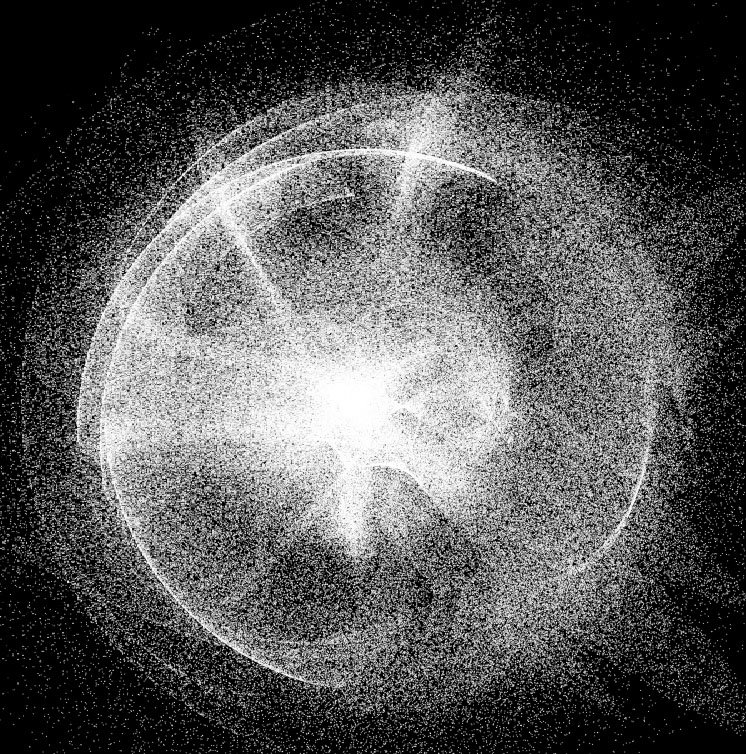
Everything, now when you start the application, you will see textured particles instead of simple points, but we will go further and add a simple effect to the resulting image.
Result of visualization:
2. Effects
For the development of effects there is a great program from NVIDIA, it is called Fx Composer . Debugging shaders, shaders version 4, DIrect3D (9, 10) and OpenGL are supported. I highly recommend, but in this article this development environment will not be considered.
First, consider the basic structure of effects:
Hidden text
float4x4 WorldViewProj; // . 4x4 // texture Base < string UIName = "Base Texture"; string ResourceType = "2D"; >; //, sampler2D BaseTexture = sampler_state { Texture = <Base>; AddressU = Wrap; AddressV = Wrap; }; //, struct VS_INPUT { float4 Position : POSITION0; float2 Tex : TEXCOORD0; }; // struct VS_OUTPUT { float4 Position : POSITION0; float2 Tex : TEXCOORD0; }; // VS_OUTPUT mainVS(VS_INPUT Input) { VS_OUTPUT Output; Output.Position = mul( Input.Position, WorldViewProj ); Output.Tex = Input.Tex; return( Output ); } // float4 mainPS(float2 tex: TEXCOORD0) : COLOR { return tex2D(BaseTexture, tex); } // "" technique technique0 { // pass p0 { CullMode = None; // // VertexShader = compile vs_2_0 mainVS(); // PixelShader = compile ps_2_0 mainPS(); // } } As you can see from the code, each of the shaders accepts and returns some value. The vertex shader must return the coordinates of the vertex, and the pixel color of the pixel being processed.
The effect is divided into several techniques . Each of the techniques can represent their own way of applying effects, or a different effect altogether.
Each technique has one or more visualization passes.
It is time to write your simple effect, which, for example, will paint the particles red:
Hidden text
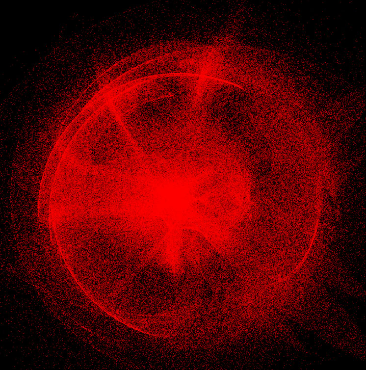
float4x4 WorldViewProj; // . 4x4 // () texture Base < string UIName = "Base Texture"; string ResourceType = "2D"; >; //, sampler2D BaseTexture = sampler_state { Texture = <Base>; AddressU = Wrap; AddressV = Wrap; }; //, struct VS_INPUT { float4 Position : POSITION0; float2 Tex : TEXCOORD0; }; // struct VS_OUTPUT { float4 Position : POSITION0; float2 Tex : TEXCOORD0; }; // VS_OUTPUT mainVS(VS_INPUT Input) { VS_OUTPUT Output; Output.Position = mul( Input.Position, WorldViewProj ); // Output.Tex = Input.Tex; // return( Output ); } // float4 mainPS(float2 tex: TEXCOORD0) : COLOR { return tex2D(BaseTexture, tex) * float4(1.0, 0, 0, 1.0); // } // "" technique technique0 { // pass p0 { CullMode = None; // // VertexShader = compile vs_2_0 mainVS(); // PixelShader = compile ps_2_0 mainPS(); // } } The code for this effect differs little from the basic structure previously considered by us. We have added only mixing with red color by multiplication method (multiply blend). Here's what we got:
Not bad, but you can change the blend mode to another, and make blending not with one color, but with the whole texture.
In order for us to get the right mix of particle visualization and texture, we need to use a technique called Render Target (visualization target). The essence of the technique is simple, we visualize our scene in texture, and then apply effects to the already rasterized image.
Here is the full effect code of this effect:
Hidden text
float4x4 WorldViewProj; texture Base < string UIName = "Base Texture"; string ResourceType = "2D"; >; sampler2D BaseTexture = sampler_state { Texture = <Base>; AddressU = Wrap; AddressV = Wrap; }; texture Overlay < string UIName = "Overlay Texture"; string ResourceType = "2D"; >; sampler2D OverlayTexture = sampler_state { Texture = <Overlay>; AddressU = Wrap; AddressV = Wrap; }; // , texture PreRender : RENDERCOLORTARGET < string Format = "X8R8G8B8" ; >; // sampler2D PreRenderSampler = sampler_state { Texture = <PreRender>; }; struct VS_INPUT { float4 Position : POSITION0; float2 Tex : TEXCOORD0; }; struct VS_OUTPUT { float4 Position : POSITION0; float2 Tex : TEXCOORD0; }; VS_OUTPUT cap_mainVS(VS_INPUT Input) { VS_OUTPUT Output; Output.Position = mul( Input.Position, WorldViewProj ); Output.Tex = Input.Tex; return( Output ); } float4 cap_mainPS(float2 tex: TEXCOORD0) : COLOR { return tex2D(BaseTexture, tex); } /////////////////////////////////////////////////////// struct Overlay_VS_INPUT { float4 Position : POSITION0; float2 Texture1 : TEXCOORD0; }; struct Overlay_VS_OUTPUT { float4 Position : POSITION0; float2 Texture1 : TEXCOORD0; float2 Texture2 : TEXCOORD1; }; vector blend(vector bottom, vector top) { //Linear light float r = (top.r < 0.5)? (bottom.r + 2*top.r - 1) : (bottom.r + top.r); float g = (top.g < 0.5)? (bottom.g + 2*top.g - 1) : (bottom.g + top.g); float b = (top.b < 0.5)? (bottom.b + 2*top.b - 1) : (bottom.b + top.b); return vector(r,g,b,bottom.a); } Overlay_VS_OUTPUT over_mainVS(Overlay_VS_INPUT Input) { Overlay_VS_OUTPUT Output; Output.Position = mul( Input.Position, WorldViewProj ); Output.Texture1 = Input.Texture1; Output.Texture2 = Output.Position.xy*float2(0.5,0.5) + float2(0.5,0.5); // , return( Output ); } float4 over_mainPS(float2 tex :TEXCOORD0, float2 pos :TEXCOORD1) : COLOR { return blend(tex2D(OverlayTexture, pos), tex2D(PreRenderSampler, tex)); } technique technique0 { pass p0 { CullMode = None; VertexShader = compile vs_2_0 cap_mainVS(); PixelShader = compile ps_2_0 cap_mainPS(); } pass p1 { CullMode = None; VertexShader = compile vs_2_0 over_mainVS(); PixelShader = compile ps_2_0 over_mainPS(); } } As you noticed, there is another stage of visualization. At the first stage, we visualize particles as they are. And the visualization we will need to perform in texture. And already in the second pass of the visualization, we impose another texture on the image using Linear Light blending.
Using effects in the program
The effects we have created, it is time to change the code by adding the use of effects.
We need to create and compile an effects code, load an additional texture, and also create a texture in which we will perform visualization.
Hidden text
ID3DXBuffer* errorBuffer = 0; D3DXCreateEffectFromFile( // device, L"effect.fx", NULL, NULL, D3DXSHADER_USE_LEGACY_D3DX9_31_DLL, // DirectX 9 NULL, &effect, &errorBuffer ); if( errorBuffer ) // , { MessageBoxA(hMainWnd, (char*)errorBuffer->GetBufferPointer(), 0, 0); errorBuffer->Release(); terminate(); } // , WorldViewProj // D3DXMATRIX W, V, P, Result; D3DXMatrixIdentity(&Result); device->GetTransform(D3DTS_WORLD, &W); device->GetTransform(D3DTS_VIEW, &V); device->GetTransform(D3DTS_PROJECTION, &P); D3DXMatrixMultiply(&Result, &W, &V); D3DXMatrixMultiply(&Result, &Result, &P); effect->SetMatrix(effect->GetParameterByName(0, "WorldViewProj"), &Result); // effect->SetTechnique( effect->GetTechnique(0) ); IDirect3DTexture9 *renderTexture = NULL, *overlayTexture = NULL; // IDirect3DSurface9* orig =NULL , *renderTarget = NULL; D3DXCreateTextureFromFile(device, L"overlay.png", &overlayTexture); // , D3DXCreateTexture(device, Width, Height, 0, D3DUSAGE_RENDERTARGET, D3DFMT_X8B8G8R8, D3DPOOL_DEFAULT, &renderTexture); // , renderTexture->GetSurfaceLevel(0, &renderTarget); // device->GetRenderTarget(0, &orig); // auto hr = effect->SetTexture( effect->GetParameterByName(NULL, "Overlay"), overlayTexture); hr |= effect->SetTexture( effect->GetParameterByName(NULL, "Base"), particleTexture); hr |= effect->SetTexture( effect->GetParameterByName(NULL, "PreRender"), renderTexture); if(hr != 0) { MessageBox(hMainWnd, L"Unable to set effect textures.", L"", MB_ICONHAND); } As we can see, the effect must be compiled before use, the technique must be chosen, and all the data used by it must be installed.
To render into texture we need to create the texture itself, the size of the original scene, and the surface for it. The surface will be used for visualization.
Now we only need to draw the texture using the effect. This is done like this:
Hidden text
UINT passes = 0; // effect->Begin(&passes, 0); for(UINT i=0; i<passes; ++i) { effect->BeginPass(i); if(i == 0) { // device->Clear( 0, NULL, D3DCLEAR_TARGET, D3DCOLOR_XRGB(0,0,0), 1.0f, 0 ); // , , device->SetRenderTarget(0, renderTarget); // , device->Clear(0, NULL, D3DCLEAR_TARGET, D3DCOLOR_XRGB(0,0,0), 1.0f, 0); // DrawParticles(); } else if(i == 1) { // device->SetRenderTarget(0, orig); // , (RenderTexture) DrawRect(); } effect->EndPass(); } effect->End(); // device->Present(NULL, NULL, NULL, NULL); In the code we used DrawRect () , this function draws a rectangle over which the RenderTexture texture is applied . This is a feature of the reception, after rendering to the texture, we need to somehow display it on the screen for further processing. This is where the rectangle helps us, which we draw so that it occupies the entire screen space. I will not give the initialization code for vertices and visualization of the rectangle, so as not to inflate the article even more. I can only say that all the necessary actions are similar to those we carried out during the initialization of particles. If you have any difficulties, you can see how this function is implemented in the example code.
The effects are used like this: first we call the Begin () method, getting the number of visualization passes in the effect. Then before each pass we call BeginPass (i) , and after EndPass () . Finally, after the end of the rendering, we call the End () method.
Here's what we got:
This article ends, thank you all for your attention. I will be glad to answer any questions you may have in the comments.
The full source code for the project is available on GitHub . Attention, to run the compiled example, you must install VisualC ++ Redistributable 2012
UPD
For those who believe that D3D9 is hopelessly outdated, or those who simply want all calculations to be made on the GPU - there is one more example, only already on D3D10. As usual, the example and compiled demo are available on GitHub . Calculations on the GPU are attached :)
Source: https://habr.com/ru/post/149933/
All Articles