Modeling parametric log houses on ... C ++
Who cares how to simulate such a parametric log cabin in a few lines of C ++ code?
For several years we have been using the free version of the sgCore solid-state modeling library in our projects ( here is a brief overview of the possibilities). Recently, the authors have released a version for iOS, and since this platform is actively developing, I think that a small introductory example to this library will be interesting to many. I want to show with a small example how to use it to make a rather complex model in just a few steps.
Here are the demo project sources for this article.
iOS
mac
win
')
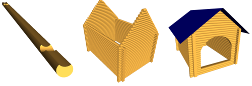
Create a model of a parametric log house. In order not to complicate things, we will introduce only three parameters - the radius of the log section, the width of the house and the length of the house. It is clear that in real problems the number of parameters will be much more, but in this example, the introduction of new parameters will not bring anything new. Thus, we need to build a model of the house that will be rebuilt by calling just one function.
void Build(sgFloat log_size, sgFloat houseSizeX, sgFloat houseSizeY); To begin with, we initialize the library core. This must be done once in the main thread before the first use of the sgCore functions:
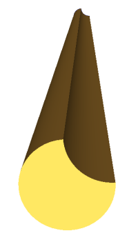
sgInitKernel(); Our first step will be the construction of the cross section of the log. To ensure that the logs are not just lay on top of each other, but form a more or less stable construction, we will make the section shape not round, but consisting of two arcs:

A log of a similar cross section can be obtained in two ways — either by creating a flat cross section itself and using a flat contour extrusion operation, or creating two cylinders of the same radius, displacing one of the cylinders, and applying a boolean subtraction operation. Since the extrusion operation is faster than boolean subtraction - so we use the first method.
Create a section of two arcs. For a snug fit of the logs to each other, these arcs should be the same radius:

To create two arcs, we need to calculate the intersection points of two surroundings of the same radius. This radius is one of the parameters of our model - therefore the function of constructing the contour of the log will have one input parameter - the radius of the log
void BuildLogSection(sgFloat log_size); Create the first arc of the section at three points:

Let the angle, which sets the intersection of these two circles, will be equal to 45 degrees. Then the points defining the first arc will have the following coordinates:
SG_POINT arc1BeginP = {log_size*cosCalc, -log_size*sinCalc, 0}; SG_POINT arc1EndP = {-log_size*cosCalc, -log_size*sinCalc, 0}; SG_POINT arc1MidP = {0, log_size, 0}; Where log_size is the radius of the log, and sinCalc and cosCalc are the sines and cosines of the angle, which, as we have agreed, is 45 degrees. By setting different angles, you can get a huge number of different options for sections, consisting of two arcs.
Create an arc structure by these three points:
SG_ARC arc1; arc1.FromThreePoints(arc1BeginP, arc1EndP, arc1MidP, false); The first three arguments are calculated points, the last argument is to invert or not the arc given by three points. If this parameter is false, then the midpoint of the arc will lie on the arc created by us, if true, then an arc will be created that complements the arc created by the first method to a complete circle.
We will create the second arc in a different way - by two end points, normals to the arc plane and radius. The end points of the second arc coincide with the end points of the first, the normal to the arc plane is the Z axis, that is, the vector (0, 1, 1), and the radius is the same as the first arc, that is, log_size. We build the structure of the second arc:
SG_ARC arc2; arc2.FromBeginEndNormalRadius(arc1BeginP, arc1EndP, zAxe, log_size, false); Next we need to build the objects themselves of the geometric kernel - the heirs of the sgCObject. For arcs, these will be objects of the class sgCArc. Since we are going to build a contour along these arcs, we immediately save our arcs into an array:
sgCObject* acrsObjs[2]; acrsObjs[0] = sgCArc::Create(arc1); acrsObjs[1] = sgCArc::Create(arc2); And we will create the contour itself, which we will later use to build the log:
m_log_section = sgCContour::CreateContour(acrsObjs, 2); After the section is built, we can create a log. Since we need to create logs of various lengths, we will create a function that extrudes our section to an arbitrary length.
sgC3DObject* BuildLog(sgFloat logH); Since we created a flat contour in the XOY plane, we will extrude the contour of the log section along the Z axis (perpendicular to the section plane):
SG_VECTOR extrVect = {0,0, logH}; sgCObject* logObj = sgKinematic::Extrude(*m_log_section, NULL, 0, extrVect, true); The first argument of the extrusion function is the outer contour that is extruded, the second argument is an array of holes in the extruded object — also flat contours that lie inside the outer contour, the third argument is the number of holes. Since there are no through holes along the entire length of the log in the logs from which the house is being built, these two arguments are null. The fourth argument is the extrusion vector - it is directed along the Z axis and has a length - logH - the argument of the log creation function. The last argument is to close the created object to a solid or simply to create a side surface of extrusion. In other words - we need to create "bottoms" or not. We have it is true.
Let's create the first log of any length and add it to our scene:
sgGetScene()->AttachObject(BuildLog(houseSizeX)); After starting the program we will see an empty scene. Where is the log ???
In fact, the log was created and it will be rendered if you use for drawing not an array of triangles of the object, but its wireframe model. So far, our log has no triangles - so we did not see anything.
In order for a three-dimensional object to appear in the form of triangles - the object must be triangulated. This can be done automatically for all created three-dimensional objects, or manually for each object. For automatic triangulation, you must enable the flag:
sgC3DObject::AutoTriangulate(true, SG_DELAUNAY_TRIANGULATION); The second argument is the type of triangulation. More types of triangulation are described in the sgCore documentation.
But there is one subtlety. Triangulation of very complex objects may take some time. And for using and working with objects, triangulation itself is not necessary - it is necessary only for visualizing the final result. Therefore, if you build complex objects as intermediate, then you should disable automatic triangulation and triangulate the final results that the user will see. Since we will have a lot of complex operations before obtaining the final result, we will therefore turn off automatic triangulation and manually triangulate only those objects that really need to be visualized.
Therefore, we slightly transform the creation of our log:
sgC3DObject* log1 = BuildLog(houseSizeX); log1->Triangulate(SG_DELAUNAY_TRIANGULATION); Here is what we get:
The next step will be the construction of grooves for each log created. The grooves are grooves in the log in those places where another log will fit to the log. We will build grooves in our logs where the logs on which this log lies will be attached to it, taking into account the indents adopted during the construction of log houses.
To do this, we expand the function of constructing a log by entering new parameters:
sgC3DObject* BuildLog(sgFloat logH, bool withGroove, sgFloat logH, bool withGroove, sgFloat groove_size, sgFloat grooveShift); withGroove - a flag, is it necessary to build a groove
groove_size - groove radius (equal to the radius of the log)
grooveShift - indent from the edge of the log, on which the groove will be built.
The groove will be two - from both ends of the log.
To build grooves we will use boolean subtraction. For speed, the subtracted object will be the cylinder. You can, of course, use another log, but since the logs will intersect in such a way that they can be considered cylinders relative to each other (a notch formed by the second arc of the extruded contour does not participate in the process of constructing the groove), we will deduct the cylinder.
Create two cylinders of radius equal to the radius of the log, of arbitrary length (the length of this temporary object does not matter, this does not affect the speed of work or the result). The most important thing at this step is to correctly place these temporary objects in the space. Since our base of the log stands on the XOY plane and is directed along the Z axis, we must also place these temporary objects accordingly. Cylinders, like primitive objects, are also created with a base on the XOY plane, with a centrum at the origin and directed along the Z axis. Thus, we first need to rotate our temporary objects around the Y axis, then shift it so that the groove depth is taken into account ( we have it will be half the thickness of the log - that is, just the parameter log_size) and indents from the edges of the log. Thus, the creation of these temporary objects will look like this:
if (withGroove) { sgFloat cylH = 10*groove_size; sgC3DObject* cyl1 = sgCreateCylinder(groove_size, cylH, 24); cyl1->InitTempMatrix()->Rotate(zeroP, yAxe, 90.0*M_PI/180.0); SG_VECTOR transVect = {-cylH/2, -groove_size, grooveShift}; cyl1->GetTempMatrix()->Translate(transVect); cyl1->ApplyTempMatrix(); cyl1->DestroyTempMatrix(); sgC3DObject* cyl2 = sgCreateCylinder(groove_size, cylH, 24); cyl2->InitTempMatrix()->Rotate(zeroP, yAxe, 90.0*M_PI/180.0); transVect.z = logH-grooveShift; cyl2->GetTempMatrix()->Translate(transVect); cyl2->ApplyTempMatrix(); cyl2->DestroyTempMatrix(); } These objects do not need to be triangulated, but let's temporarily do it and add to the scene, just to see if we have placed them:
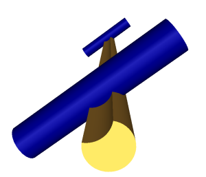
Fine. Objects are placed as needed. Remove from the code the triangulation of these objects and will not add them to the scene.
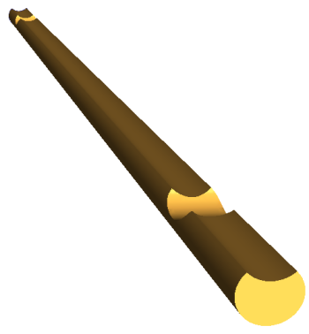
Next, you need to use a boolean subtraction to get the log in grooves.
First we subtract the first temporary object. Since, as a result of a Boolean subtraction, a group is created, there it must be broken up, the group object must be deleted, and the pointer to the first log pointer should be reassigned (and the only object from the collapsed group). In this case, we will not forget to remove that temporary cylinder, since we no longer need it, as well as the old log object:
sgCGroup* boolRes1 = sgBoolean::Sub((const sgC3DObject&)(*logObj), *cyl1); int ChCnt = boolRes1->GetChildrenList()->GetCount(); sgCObject** allChilds = (sgCObject**)malloc(ChCnt*sizeof(sgCObject*)); boolRes1->BreakGroup(allChilds); sgCObject::DeleteObject(boolRes1); sgCObject::DeleteObject(logObj); logObj = allChilds[0]; sgCObject::DeleteObject(cyl1); We will do the same with the second variable cylinder:
boolRes1 = sgBoolean::Sub((const sgC3DObject&)(*logObj), *cyl2); ChCnt = boolRes1->GetChildrenList()->GetCount(); allChilds = (sgCObject**)malloc(ChCnt*sizeof(sgCObject*)); boolRes1->BreakGroup(allChilds); sgCObject::DeleteObject(boolRes1); sgCObject::DeleteObject(logObj); logObj = allChilds[0]; sgCObject::DeleteObject(cyl2); After these two operations we get the following result:
The next step is to create the walls. In fact, this step does not bring anything new - we just have to create the necessary number of logs and place them in the appropriate places. We only say that to create the same logs, we will use the cloning function of the object (Clone ()), and not the creation from scratch. Let us skip here the description of where a log should be located, and just show the steps for constructing the walls:
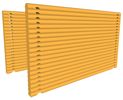
So the walls are built. Now we have a fully parametric model of the foundation of a house, and it fully meets the physical requirements of logging into each other - through solid-state operations with objects. This means that our house model is created not just for display, but completely corresponds to a house that is actually being built.
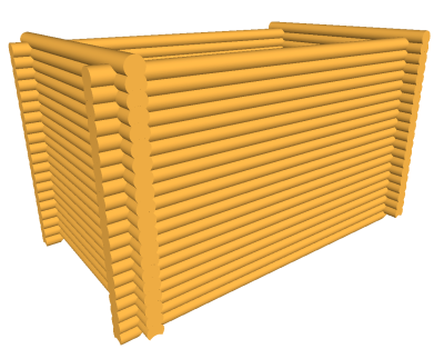
Let's change the parameters a bit and see how it will change the house:

As you can see, having a parametric model, and changing only a few numbers, you can easily get an infinite number of models.
The next step is to add to the window model.
To build the window, we use two operations: extrusion and boolean subtraction. Of course, in real houses there are usually rectangular windows, but we want to make a window of some unusual shape, so we will use not just a temporary box (as could be done in the case of a rectangular window), but extrude a rounded contour.
So, first create such a contour. It will consist of an arc and three segments. The functions of creating a contour and its extrusion are completely analogous to those used in the creation of the log, so we will not focus on this. After extruding the contour of the window and placing it in the required place, we get the following:
We will subtract our window from the logs of the very first wall. Therefore, we will disable their triangulation in the function of their creation and then we will triangulate the results of applying the subtraction window. In order to subtract a window from a wall, it is necessary to subtract the window object from each wall log. You can do this more optimally, because we know where exactly what log is located and where the window is located and apply a Boolean operation only to those logs that really intersect with the window. But we will be laid on the result of a boolean subtraction. If it is zero, then the objects do not overlap. It is also necessary to take into account that in this case the result of Boolean operations may consist of several objects (the window divides the log into two). Do not forget after all the boolean operations to delete the temporary object and the old logs:
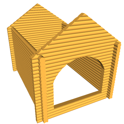
size_t oldCnt = m_walls[0].size(); for (int i=0;i<oldCnt;i++) { sgCGroup* boolRes = sgBoolean::Sub(*m_walls[0][i], *winObj); if (boolRes) { int ChCnt = boolRes->GetChildrenList()->GetCount(); sgCObject** allChilds = (sgCObject**)malloc(ChCnt*sizeof(sgCObject*)); boolRes->BreakGroup(allChilds); sgCObject::DeleteObject(boolRes); sgGetScene()->DetachObject(m_walls[0][i]); sgDeleteObject(m_walls[0][i]); for (int j=0;j<ChCnt;j++) { ((sgC3DObject*)allChilds[j])->Triangulate(SG_VERTEX_TRIANGULATION); sgGetScene()->AttachObject(allChilds[j]); } m_walls[0][i] = (sgC3DObject*)allChilds[0]; for (int j=1;j<ChCnt;j++) m_walls[0].push_back((sgC3DObject*)allChilds[j]); free(allChilds); } else m_walls[0][i]->Triangulate(SG_VERTEX_TRIANGULATION); } sgDeleteObject(winObj); After that, we get a house model with a window:

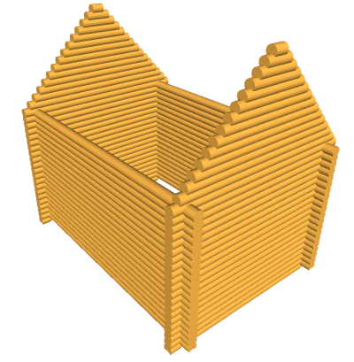
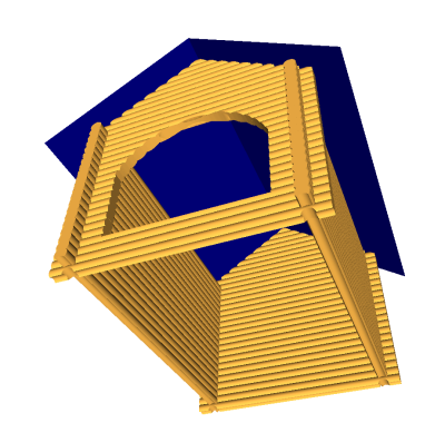
The last step is to add a ramp. We will do this in two stages - first we cut the logs that will intersect in the roof surface, then we will create the ramp surface itself.
To begin, remove all calls triangulations of all previously created is ancient. When creating the roof will be used to truncate all the logs of the roof surface - that is, boolean subtraction. Triangulate all the results of these subtractions.
So, using the extrusion operation, we will create a temporary object that will truncate our logs under the roof surface:
And we will subtract this temporary object from all logs in the same way that the window was subtracted from the logs of the first wall:
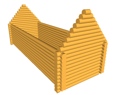
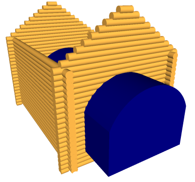
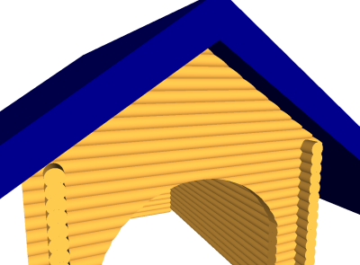
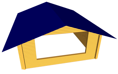
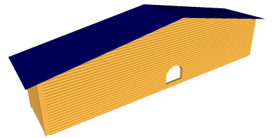
It remains only to create the surface of the slope. To do this, we also use the extrusion operation. Then we get the finished model of the log house:
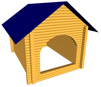
As well as an infinite number of variations of this model, by varying the parameters:

Source: https://habr.com/ru/post/149896/
All Articles