nanoCAD 3.7 vs 4.0 - what is new? (part number 1)
This summer, our company had two events: the release of the new version of nanoCAD 4.0 and the update of the free version of nanoCAD 3.5 to version 3.7 (we discussed the reasons for this step in the previous article “ Double star nanoCAD: free 3.7 and paid 4.0 ”). And, of course, questions began to come in from users: how are they different? and what is better to use? To answer these questions, of course, you need to get into the technical description of the new features of each product and compare. And then decide for yourself what suits you best.
We decided to help you a little - by describing each new / optimized function, we will put a special icon next to it - which version of the program it is included ... And you already choose the solution for you.
Let's start with the new features that were not previously in nanoCAD ...
Some preliminary statements
Statement No. 1 : in general, the nanoCAD core has not changed - from a technical point of view, both 3.7 and 4.0 are identical. This means that errors found in previous versions are fixed at the same time there and there.')
Statement # 2 : nanoCAD 4.0 - mainly aimed at professional users. This means that version 4.0 includes features that automate drafting. Therefore, we can say that work in nanoCAD 4.0 is more productive. This is the main message in the functional separation of versions 4.0 and 3.7.
Statement number 3 : nanoCAD 3.7 is a massive electronic drawing board. Tool for the production and release of drawings. With minimal automation. It is believed that in nanoCAD 3.7 performance is not so important and the user has time for a more meticulous drawing. At the same time, the free version of nanoCAD legally and license gives the right of commercial use. Made specifically so that the user does not bother about the questions: “can it be used in this case?”, “And if I bring to work?” ... Carry, work, use ... The main thing is not to hack :-)
New functionality
Historically, we all divide the innovations into three categories:- New functionality - i.e. features that were not previously in nanoCAD;
- Optimized functionality - i.e. the functions that were previously, but according to user feedback, they had to be improved and optimized;
- Corrected functionality - i.e. functions that, as it turned out as a result of mass use, did not work correctly. Unfortunately, we also make mistakes; Thank God for fixing :-)
So, in this post we look at the new functionality, which is designed to improve the usability of working on drawings and multiply the number of users of nanoCAD.
Extended work with layers
 Let's start with one of the frequently used functions of any CAD system - working with layers. In nanoCAD 4.0, the set of tools for this purpose has been significantly expanded: in the Format / Layer Tools menu and on the new Layers 2 toolbar (Fig. 2a and 2b), eight new commands are presented. Among them, Isolating the layer (quickly hide the layers of unselected objects), Make the object layer current (and thus quickly change the current layer), the ability to show / hide / freeze / close / open the layer of the selected object.
 In addition, lists of configurations and groups of layers are displayed on the Layers 2 panel, which allows you to quickly switch between different sets of settings - very convenient when working with rich drawings (in nanoCAD 3.7, these lists are on the Properties panel).
) 2 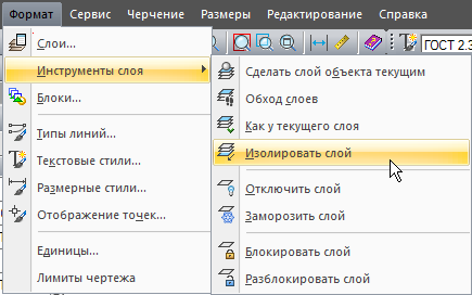
) \ . 1. 2 nanoCAD 4 Also, a nice improvement appeared in the Layers dialog: double clicking on the column separator in the table header will ensure automatic selection of the column width - this method is familiar with Windows programs.Team Bypass Layers
We should also mention the Laywalk command , which the developers even brought to the standard Properties panel, as it is convenient and important for drawing. The principle of operation of this command (slightly different from the similar command in other CAD programs) is logical and simple. The command first turns off the visibility of all layers except the current one, and then dynamically turns on / off the visibility of the specified layers in the drop-down list of layers of the Properties panel (Fig. 2). This allows you to quickly analyze the structure of * .dwg-drawing and instantly return to the original state - try and appreciate the convenience of such a solution!By the way, if you select any objects in the drawing, then by calling the Bypass layers command, you will immediately leave the layers on which the selected objects are located ...
. 2. *.dwg- Additional editing modes through the handles of selected objects
All users know what the selection handles are: if you select certain objects in the drawing, they have special points through which the selected primitives are edited. In previous versions of nanoCAD, these handles made it possible to quickly edit the shape of polygons by pressing the CTRL key: add / delete vertices, round edges. In version 4.0, the handles have additional modes that are sorted by the SPACE or ENTER key: move, rotate, scale and mirror (Fig. 3). Working on a drawing has become more familiar and much more pleasant.
. 3. nanoCAD , «» , : , , , Team TEXT2MTEXT
Experienced CAD users know a great feature from the ExpressTools suite that converts a set of single-line texts into more modern multi-line text. Now there is a similar command in nanoCAD - by working on drawings, you can quickly convert one text format to another. Simply type TEXT2MTEXT or a short T2MT alias on the command line.Insert block from hard disk
In nanoCAD 4, a seemingly unnoticeable at first glance, but a very useful improvement of the Insert Box dialog, which will greatly simplify the designer’s life, appeared. I'm talking about the new Open button ... in the Insert / Block dialog ... , which allows the user to insert any * .dwg-drawing as a block into the current document (Fig. 4). I think there is no need to paint for a long time how convenient it is now to use a library of standard products made in separate * .dwg files. Click - and the block you specified is loaded into the current project!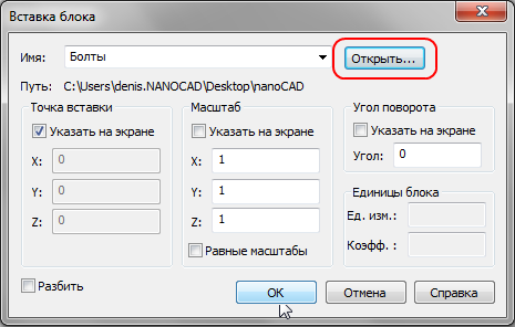
. 4. *.dwg- Bindings to raster objects
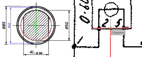
As you probably know, in all CAD systems, bitmap images placed in a * .dwg drawing are just a background substrate. You can draw over it, turn on / off its visibility, but you do not have access to the contents of the bitmap itself. But not in nanoCAD! For the new version of nanoCAD, a monochrome raster drawing is not just a substrate; This is a set of objects to which you can attach (Fig. 5). So drawing over a raster is carried out not by the eye, but quickly and accurately.To work with this function, you just need to select a new type of binding in the menu for setting bindings - Raster . Then simply move the cursor to the raster line, and you will catch all types of standard bindings (closest, point, center, quadrant, etc.).
) 
) . 5. nanoCAD 4 – , What can this function be used for? For example, to quickly “chop” a raster drawing and get a vector document. Or just modify the area of the scanned drawing. Or modify the standard drawing from the NormaCS database by placing it in nanoCAD via the clipboard ... There are many applications of this unique function, and you will find it only in nanoCAD 4!
Print to PDF
Although the operating system allows you to select and install a virtual PDF printer for any taste, many users have asked to include the ability to output documentation in PDF format in the standard nanoCAD package. Version 4.0 also responds to these wishes: an additional virtual Embedded PDF printer has appeared in the list of printers in the Print dialog. And the Print to PDF dialog (Fig. 6), which is called by pressing the Settings button located next to the printer, allows you to set additional drawing output parameters: various paper sizes (including multiples), print resolution, save folder, print mode (add new sheets in existing sheet or replace old versions).
) PDF-… 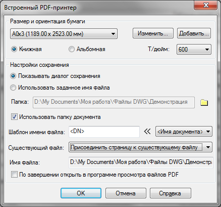
) … . 6. nanoCAD 4.0 PDF PDF- Print Improvements
Of course, the built-in PDF printer is a powerful feature that will appeal to almost any designer. But other improvements have been made to the printing system. For example, in the Print dialog, a new Color-dependent mode option appears that controls the composition of the Print Style Table drop-down list. When the checkbox is on the list, color-dependent print styles (* .ctd) are displayed in the list, and if it is cleared, the named (* .std) colors are shown (see Figure 7).
. 7. , . System administrators of design organizations will like the new dialogs for adding and changing paper sizes - they have become more visual. And besides, they now have the opportunity to indent and form print fields in this way (Fig. 8).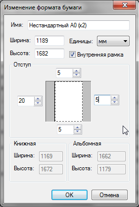
. 8. – / Support for files containing PDF underlays
The new version also supports files created in other CAD-systems and containing PDF substrates. At the same time, in nanoCAD, you can change the position, scale and angle of rotation of the substrate, and in the Properties window, its display settings are available: it is possible to change the set settings for contrast, merging with the background and monochrome. The outline of the substrate can be displayed and printed (in the same way as in the case of raster images) - the system variable PDFFRAME is used for this.The conclusion of part number 1
And this is just the new features of the new nanoCAD. The next part will be devoted to optimized functions - in it we will also consider what appeared only in nanoCAD 4.0, and what is implemented, including in 3.7.How are nanoCAD 3.7 and 4.0 distributed?
Both versions are distributed with minimal control from our side: nanoCAD can be downloaded and installed without registration. In this case, the program will run in demo mode.The technical limitation of the demo mode is the same: when printing across the drawing field, the inscription “Demo version” is randomly displayed. There is also a legal restriction - the demo version is not allowed to be used in commercial mode.
For commercial use of nanoCAD, you need to register on the developer’s site and either purchase ( nanoCAD 4.0 ), or get a free license for the right to use the Personal Account \ License Management (in the case of using the free nanoCAD 3.7 ).
Your questions / wishes? :-)
UPG: Continuation of the publication here: http://habrahabr.ru/company/nanosoft/blog/150536
Source: https://habr.com/ru/post/149873/
All Articles